Page 56 of 909
FRONT OIL SEAL
B2–25
B2
Front Oil Seal Removal Note
1. Cut the oil seal lip using a razor knife.
2. Remove the oil seal using a screwdriver protected
with a rag.
Front Oil Seal Installation Note
1. Apply clean engine oil to the oil seal lip.
2. Push the oil seal slightly in by hand.
3. Tap the oil seal in evenly using the SST and a
hammer. The oil seal must be tapped in until it is
flush with the edge of the oil pump body.
End Of Sie
OIL SEAL LIP
A6E2320W103
RAG
A6E2320W104
49 U027 003
0—0.5 mm {0—0.019 in}
HAMMEROIL PUMP BODY
FRONT OIL SEAL
A6E2320W105
Page 57 of 909
B2–26
REAR OIL SEAL
REAR OIL SEAL REPLACEMENTA6E2322113992011. Remove the flywheel. (See H–5 CLUTCH UNIT REMOVAL/INSTALLATION (A65M-R manual transaxle
models).)
2. Remove in the order indicated in the table.
3. Install in the reverse order of removal.
.
Rear Oil Seal Removal Note
1. Cut the oil seal lip using a razor knife.
2. Remove the oil seal using a screwdriver protected
with a rag.
Rear Oil Seal Installation Note
1. Apply clean engine oil to the oil seal lip.
2. Push the oil seal slightly in by hand.
3. Tap the oil seal in evenly using the SST and a
hammer.
End Of Sie
REAR OIL SEAL
1 Rear oil seal
(See B2–26 Rear Oil Seal Removal Note)
(See B2–26 Rear Oil Seal Installation Note)
SST
R
OILOIL1
A6E2322W100
OIL SEAL LIP
A6E2322W101
RAG
A6E2322W102
0—0.5 mm
{0—0.019 in}
HAMMERREAR COVER
REAR OIL SEAL
49 G033 107A
A6E2322W103
Page 93 of 909
OUTLINE
F1–5
F1
11 Knock sensor
12 CKP sensor
13 CMP sensor
14 Fuel injector No.1
15 Fuel injector No.2
16 Fuel injector No.3
17 Fuel injector No.4
18 IAC valve
19 Oxygen sensor heater (front)
20 Oxygen sensor heater (rear)
21 A/C relay22 Cooling fan relay
23 Cooling fan relay
24 Cooling fan relay
25 TR switch
26 Fuel pump relay
27 Coil
28 Security light
29 Ignition switch
30 Main relay
31 TR switch
32 Starter relay
Page 94 of 909
F1–6
OUTLINE
.
1AA
1Q
1Z
1AC
1K
1C1D 4M4R 4N4K 4H4E
4T 4C4U 1AD1B 1A 2AB4X
39
38
37
35
36
33
40
45
46
44
43
41
42
34
48
47
A6E39022002
33 Generator
34 Refrigerant pressure switch (middle)
35 PSP switch
36 Blower motor
37 Refrigerant pressure switch (high and low)
38 A/C switch
39 Brake switch
40 Brake light41 Ignition coil
42 Generator
43 Purge solenoid valve
44 VAD control solenoid valve
45 EGR valve
46 Variable tumble control solenoid valve
47 VIS control solenoid valve
48 OCV
Page 96 of 909
F1–8
OUTLINE
.
15 Fuel injector No.2
16 Fuel injector No.3
17 Fuel injector No.4
18 IAC valve
19 Oxygen sensor heater (front)
20 Oxygen sensor heater (rear)
21 A/C relay22 Cooling fan relay
23 Cooling fan relay
24 Cooling fan relay
25 Cooling fan relay
26 Fuel pump relay
27 Ignition switch
28 Main relay
1AA
1Q
1Z
1AC
1K
1C1D 4M4R 4N4K 4H4E
4T 4C4U 1AD1B 1A 2AB4X
39
38
37
35
36
33
31
32
40
44
43
41
42
34
29
30
A6E39022004
29 Generator
30 Refrigerant pressure switch (middle)
31 PSP switch
32 Blower motor
33 Refrigerant pressure switch (high and low)
34 A/C switch
35 Brake switch
36 Brake light37 Ignition coil
38 Generator
39 Purge solenoid valve
40 VAD control solenoid valve
41 EGR valve
42 Variable tumble control solenoid valve
43 VIS control solenoid valve
44 OCV
Page 109 of 909

CONTROL SYSTEM
F1–21
F1
CONTROLLER AREA NETWORK (CAN)A6E394018880205•PCM transmit/received the information in the CAN. For detail information of the CAN, see the “MULTIPLEX
COMMUNICATION SYSTEM.” (See T–3 OUTLINE.)
Transmit Information (4WD ATX Model)
•Engine control condition
•Torque reduction inhibit
•Engine speed
•Vehicle Speed
•TP
•Engine torque (without torque reduction)
•Engine torque (with torque reduction)
•Battery reconnection
•Engine loss torque
•ECT
•Travelled distance
•Fuel injection information
•MIL condition
•Generator warning light conditions
•Engine displacement
•Number of cylinders
•Air induction type
•Fuel type and delivery
•Country
•Transmission/axle type
•Tire circumference (front/rear)
Received Information (4WD ATX Model)
From ABS HU/CM, ABS/TCS HU/CM, or DSC HU/CM
•Wheel speed
—Front left, Front right, Rear left, and Rear right
•Travelled distance
•Brake system status
•Torque reduction request
•Brake system configuration
From TCM
•Desired torque
•Upper torque limit
•Turbineshaft speed
•Vehicle speed
•Torque reduction request
•Idle speed up request
•Racing select determination
•MIL indicate request
•Desired gear/selector lever position
•AT warning indicator light condition
•TCC condition
End Of Sie
Page 110 of 909

F1–22
OUTLINE, ENGINE TUNE-UP
SUPPLEMENTAL SERVICE INFORMATIONA6E390218881206•The following changes and/or additions have been made since publication of the Mazda6 Workshop Manual
(1621-10-98E).
Idle speed
•Adjustment procedure has been modified.
Fuel tank
•Removal/installation procedure has been modified.
Fuel pump unit
•Removal/installation procedure has been modified.
Quick release connector (fuel tank side, transfer hose part)
•Removal/installation procedure has been added.
Exhaust system
•Removal/installation procedure has been modified.
PCM
•Inspection procedure has been modified.
On-board diagnostic
•Inspection procedure has been modified.
Troubleshooting
•Inspection procedure has been modified.
End Of Sie
IDLE SPEED INSPECTION (4WD)A6E390802000201
Note
•Ignition timing is not adjustable.
•Ignition timing verification requires WDS or equivalent.
1. Turn off the electrical loads.
2. Warm up the engine as follows.
(1) Start the engine.
(2) Maintain the engine speed at approx. 3,000 rpm until the cooling fans start to operate.
(3) Release the accelerator pedal.
(4) Wait until the cooling fans stop.
3. Verify that the idle speed (WDS: RPM PID) is within the specification using WDS or equivalent.
Idle speed
*1 : Excludes temporary idle speed drop just after the electrical loads are turned on.
*2 : Blower motor is operating at high speed. Headlight switch is turned on. Rear window defroster switch is turned
on. Cooling fans are operating.
End Of Sie
OUTLINE
ENGINE TUNE-UP
Condition
Engine speed (rpm)*1
No load 650—750
Electrical loads*
2 ON650—750
P/S ON 650—750
A/C ON and refrigerant
pressure switch (middle) OFF650—750
A/C ON and refrigerant
pressure switch (middle) ON700—800
Page 116 of 909

F1–28
FUEL SYSTEM
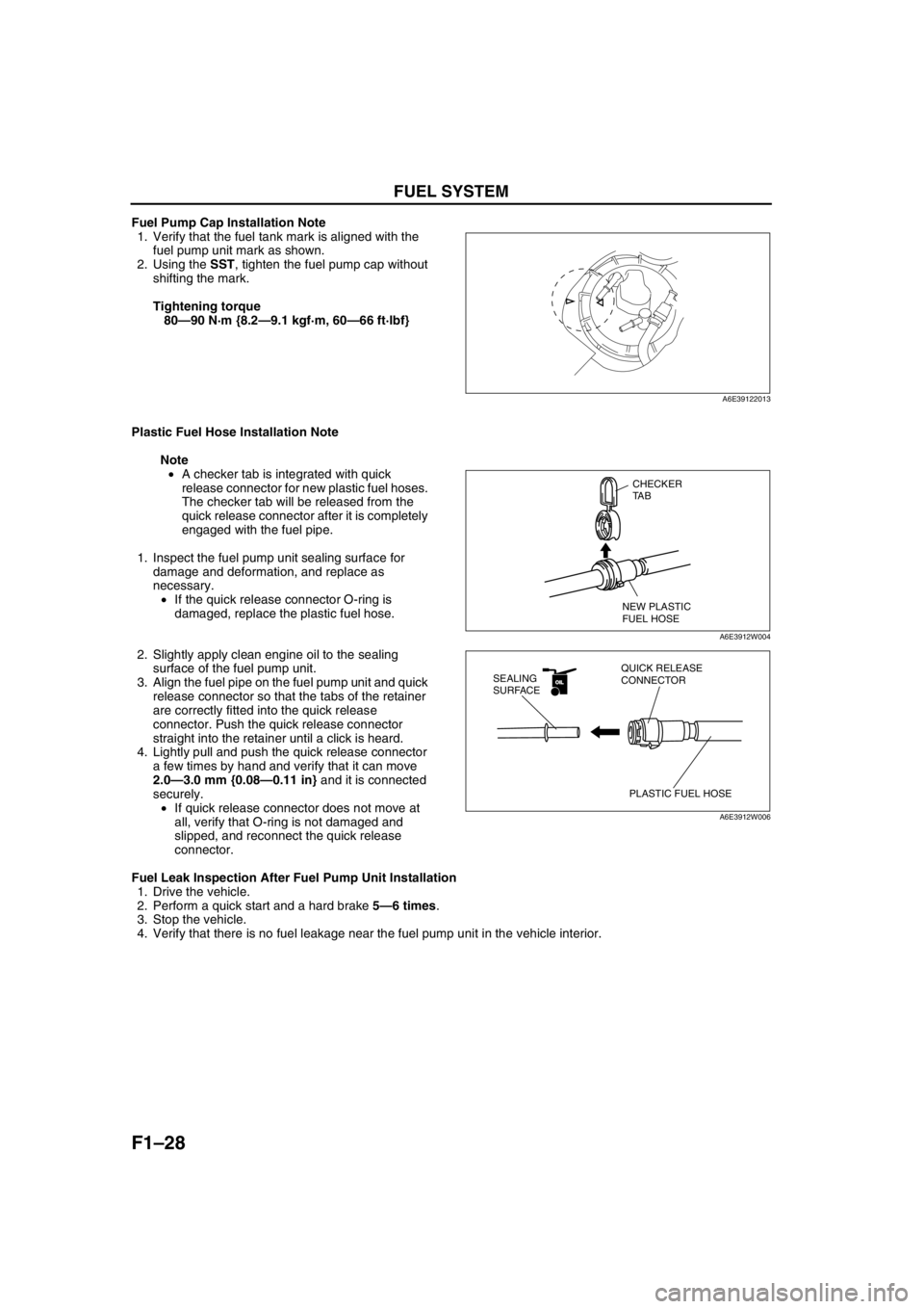
Fuel Pump Cap Installation Note
1. Verify that the fuel tank mark is aligned with the
fuel pump unit mark as shown.
2. Using the SST, tighten the fuel pump cap without
shifting the mark.
Tightening torque
80—90 N·m {8.2—9.1 kgf·m, 60—66 ft·lbf}
Plastic Fuel Hose Installation Note
Note
•A checker tab is integrated with quick
release connector for new plastic fuel hoses.
The checker tab will be released from the
quick release connector after it is completely
engaged with the fuel pipe.
1. Inspect the fuel pump unit sealing surface for
damage and deformation, and replace as
necessary.
•If the quick release connector O-ring is
damaged, replace the plastic fuel hose.
2. Slightly apply clean engine oil to the sealing
surface of the fuel pump unit.
3. Align the fuel pipe on the fuel pump unit and quick
release connector so that the tabs of the retainer
are correctly fitted into the quick release
connector. Push the quick release connector
straight into the retainer until a click is heard.
4. Lightly pull and push the quick release connector
a few times by hand and verify that it can move
2.0—3.0 mm {0.08—0.11 in} and it is connected
securely.
•If quick release connector does not move at
all, verify that O-ring is not damaged and
slipped, and reconnect the quick release
connector.
Fuel Leak Inspection After Fuel Pump Unit Installation
1. Drive the vehicle.
2. Perform a quick start and a hard brake 5—6 times.
3. Stop the vehicle.
4. Verify that there is no fuel leakage near the fuel pump unit in the vehicle interior.
End Of Sie
A6E39122013
CHECKER
TA B
NEW PLASTIC
FUEL HOSE
A6E3912W004
OILOIL
PLASTIC FUEL HOSE QUICK RELEASE
CONNECTOR SEALING
SURFACE
A6E3912W006