2002 LAND ROVER DISCOVERY steering wheel
[x] Cancel search: steering wheelPage 1116 of 1672
RESTRAINT SYSTEMS
REPAIRS 75-21
Refit
CAUTION: The SRS diagnostic control unit
is a shock sensitive device and must be
handled with extreme care.
1.Position DCU to body and connect multiplug.
2.Fit and tighten DCU Torx bolts to 10 Nm (7
lbf.ft).
3.Fit centre console.
lOn manual gearbox models:
+ INTERIOR TRIM COMPONENTS,
REPAIRS, Console - centre - manual
models.
lOn automatic gearbox models:
+ INTERIOR TRIM COMPONENTS,
REPAIRS, Console - centre - automatic
models.
4.Connect battery leads, earth lead last.
Rotary coupler
$% 76.74.20
WARNING: It is imperative that before any work
is undertaken on the SRS system the appropriate
information is read thoroughly.
WARNING: Always disconnect both battery leads
before beginning work on the SRS system.
Disconnect the negative battery lead first. Never
reverse connect the battery.
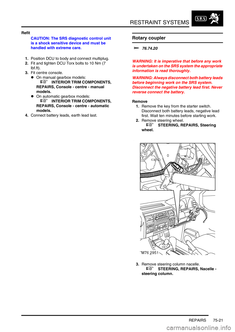
Remove
1.Remove the key from the starter switch.
Disconnect both battery leads, negative lead
first. Wait ten minutes before starting work.
2.Remove steering wheel.
+ STEERING, REPAIRS, Steering
wheel.
3.Remove steering column nacelle.
+ STEERING, REPAIRS, Nacelle -
steering column.
Page 1117 of 1672
RESTRAINT SYSTEMS
75-22 REPAIRS
4.Release rotary coupler multiplug from bracket
and disconnect from harness.
5.Disconnect rotary coupler multiplug from
harness.
6.Remove rotary coupler.
Refit
1.Fit rotary coupler to steering column and
connect multiplug to harness.
2.Connect rotary coupler multiplug to harness
and secure to bracket.
3.Fit steering column nacelle.
+ STEERING, REPAIRS, Nacelle -
steering column.
4.Fit steering wheel.
+ STEERING, REPAIRS, Steering
wheel.
Airbag deployment tool - self test
$% 76.74.99
Test
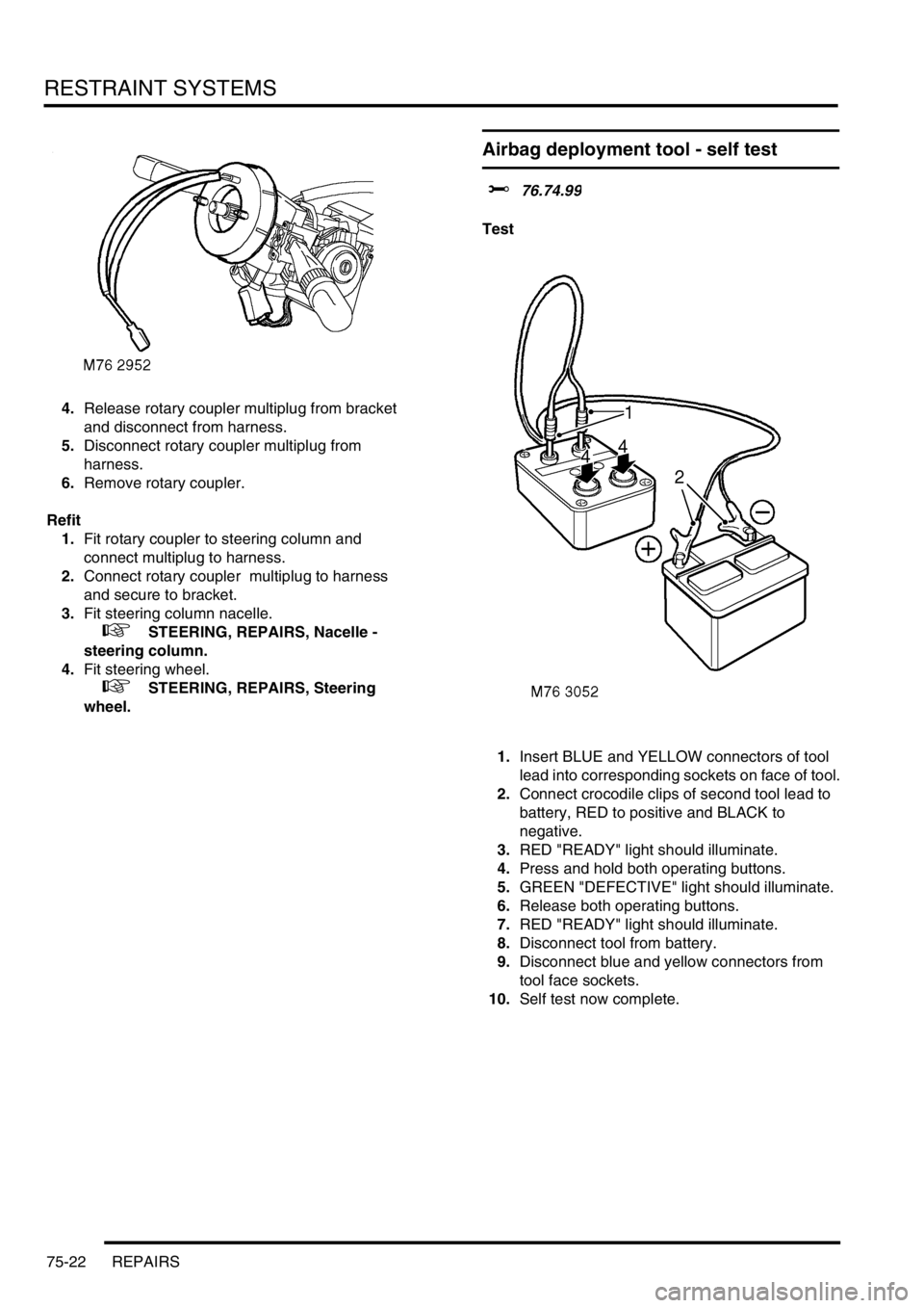
1.Insert BLUE and YELLOW connectors of tool
lead into corresponding sockets on face of tool.
2.Connect crocodile clips of second tool lead to
battery, RED to positive and BLACK to
negative.
3.RED "READY" light should illuminate.
4.Press and hold both operating buttons.
5.GREEN "DEFECTIVE" light should illuminate.
6.Release both operating buttons.
7.RED "READY" light should illuminate.
8.Disconnect tool from battery.
9.Disconnect blue and yellow connectors from
tool face sockets.
10.Self test now complete.
Page 1118 of 1672
RESTRAINT SYSTEMS
REPAIRS 75-23
Airbag module - drivers - deployment
$% 76.74.99
These guidelines are written to aid authorised
personnel to carry out the safe disposal of airbag
modules when removed from the vehicle.
If a vehicle is to be scrapped and contains an
undeployed airbag module, the module must be
manually deployed. This operation should only
be carried out using the following recommended
manual deployment procedure. Before
deployment is started the deployment tool self
test procedure should be carried out.
WARNING: Only use approved deployment
equipment, and only deploy SRS components in
a well ventilated designated area. Ensure SRS
components are not damaged or ruptured before
deployment. Notify the relevant authorities.
CAUTION: Deployment in the vehicle will damage
the steering wheel. If the vehicle is not being
scrapped, deploy the module away from the
vehicle in accordance with the correct
procedure.
Deploy
1.Carry out deployment tool self test.
+ RESTRAINT SYSTEMS, REPAIRS,
Airbag deployment tool - self test.
2.Remove airbag module from steering wheel.
+ RESTRAINT SYSTEMS, REPAIRS,
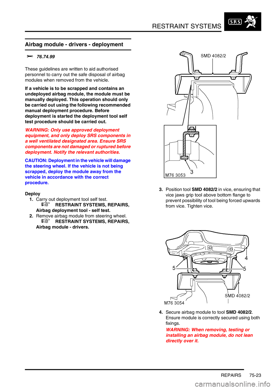
Airbag module - drivers.3.Position tool SMD 4082/2 in vice, ensuring that
vice jaws grip tool above bottom flange to
prevent possibility of tool being forced upwards
from vice. Tighten vice.
4.Secure airbag module to tool SMD 4082/2.
Ensure module is correctly secured using both
fixings.
WARNING: When removing, testing or
installing an airbag module, do not lean
directly over it.
Page 1119 of 1672
RESTRAINT SYSTEMS
75-24 REPAIRS
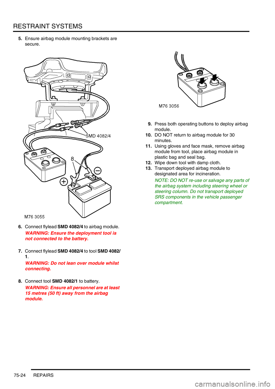
5.Ensure airbag module mounting brackets are
secure.
6.Connect flylead SMD 4082/4 to airbag module.
WARNING: Ensure the deployment tool is
not connected to the battery.
7.Connect flylead SMD 4082/4 to tool SMD 4082/
1.
WARNING: Do not lean over module whilst
connecting.
8.Connect tool SMD 4082/1 to battery.
WARNING: Ensure all personnel are at least
15 metres (50 ft) away from the airbag
module.9.Press both operating buttons to deploy airbag
module.
10.DO NOT return to airbag module for 30
minutes.
11.Using gloves and face mask, remove airbag
module from tool, place airbag module in
plastic bag and seal bag.
12.Wipe down tool with damp cloth.
13.Transport deployed airbag module to
designated area for incineration.
NOTE: DO NOT re-use or salvage any parts of
the airbag system including steering wheel or
steering column. Do not transport deployed
SRS components in the vehicle passenger
compartment.
Page 1143 of 1672
EXTERIOR FITTINGS
76-2-6 REPAIRS
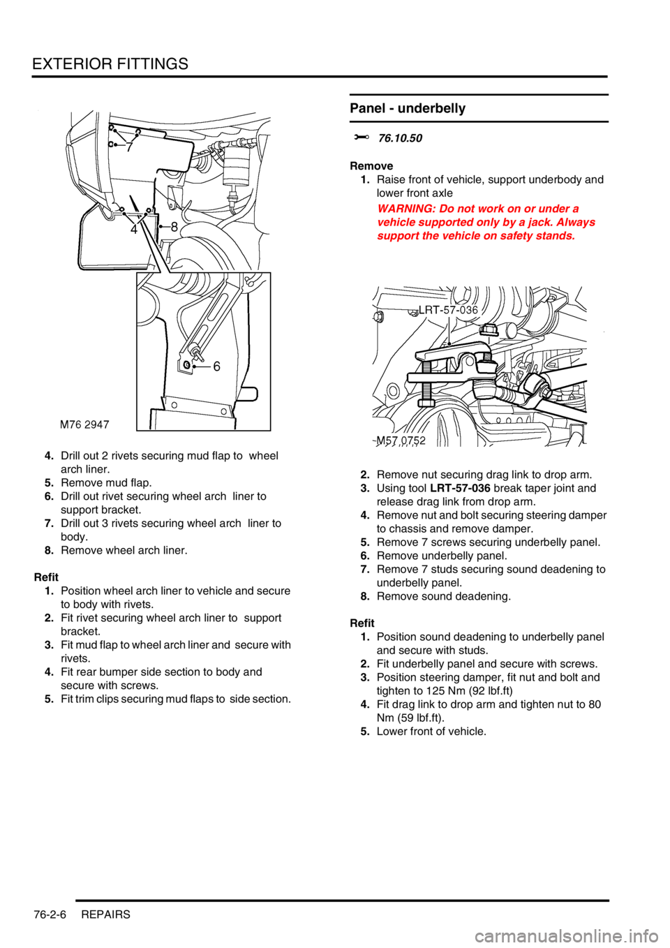
4.Drill out 2 rivets securing mud flap to wheel
arch liner.
5.Remove mud flap.
6.Drill out rivet securing wheel arch liner to
support bracket.
7.Drill out 3 rivets securing wheel arch liner to
body.
8.Remove wheel arch liner.
Refit
1.Position wheel arch liner to vehicle and secure
to body with rivets.
2.Fit rivet securing wheel arch liner to support
bracket.
3.Fit mud flap to wheel arch liner and secure with
rivets.
4.Fit rear bumper side section to body and
secure with screws.
5.Fit trim clips securing mud flaps to side section.
Panel - underbelly
$% 76.10.50
Remove
1.Raise front of vehicle, support underbody and
lower front axle
WARNING: Do not work on or under a
vehicle supported only by a jack. Always
support the vehicle on safety stands.
2.Remove nut securing drag link to drop arm.
3.Using tool LRT-57-036 break taper joint and
release drag link from drop arm.
4.Remove nut and bolt securing steering damper
to chassis and remove damper.
5.Remove 7 screws securing underbelly panel.
6.Remove underbelly panel.
7.Remove 7 studs securing sound deadening to
underbelly panel.
8.Remove sound deadening.
Refit
1.Position sound deadening to underbelly panel
and secure with studs.
2.Fit underbelly panel and secure with screws.
3.Position steering damper, fit nut and bolt and
tighten to 125 Nm (92 lbf.ft)
4.Fit drag link to drop arm and tighten nut to 80
Nm (59 lbf.ft).
5.Lower front of vehicle.
Page 1162 of 1672
INTERIOR TRIM COMPONENTS
REPAIRS 76-3-9
16.Remove console.
NOTE: Do not carry out further dismantling if
component is removed for access only.
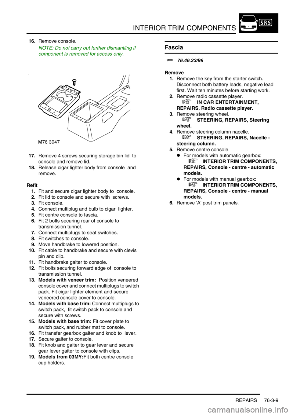
17.Remove 4 screws securing storage bin lid to
console and remove lid.
18.Release cigar lighter body from console and
remove.
Refit
1.Fit and secure cigar lighter body to console.
2.Fit lid to console and secure with screws.
3.Fit console.
4.Connect multiplug and bulb to cigar lighter.
5.Fit centre console to fascia.
6.Fit 2 bolts securing rear of console to
transmission tunnel.
7.Connect multiplugs to seat switches.
8.Fit switches to console.
9.Move handbrake to lowered position.
10.Fit cable to handbrake and secure with clevis
pin and clip.
11.Fit handbrake gaiter to console.
12.Fit bolts securing forward edge of console to
transmission tunnel.
13. Models with veneer trim: Position veneered
console cover and connect multiplugs to switch
pack. Fit cigar lighter element and secure
veneered console cover to console.
14. Models with base trim: Connect multiplugs to
switch pack, fit switch pack to console and
secure with screws.
15. Models with base trim: Fit cover plate to
switch pack, and rubber mat to console.
16.Fit transfer gearbox gaiter and knob to lever.
17.Secure gaiter to console.
18.Fit knob and gaiter to gear lever and secure
gear lever gaiter to console with clips.
19. Models from 03MY:Fit both centre console
cup holders.
Fascia
$% 76.46.23/99
Remove
1.Remove the key from the starter switch.
Disconnect both battery leads, negative lead
first. Wait ten minutes before starting work.
2.Remove radio cassette player.
+ IN CAR ENTERTAINMENT,
REPAIRS, Radio cassette player.
3.Remove steering wheel.
+ STEERING, REPAIRS, Steering
wheel.
4.Remove steering column nacelle.
+ STEERING, REPAIRS, Nacelle -
steering column.
5.Remove centre console.
lFor models with automatic gearbox:
+ INTERIOR TRIM COMPONENTS,
REPAIRS, Console - centre - automatic
models.
lFor models with manual gearbox:
+ INTERIOR TRIM COMPONENTS,
REPAIRS, Console - centre - manual
models.
6.Remove 'A' post trim panels.
Page 1165 of 1672
INTERIOR TRIM COMPONENTS
76-3-12 REPAIRS
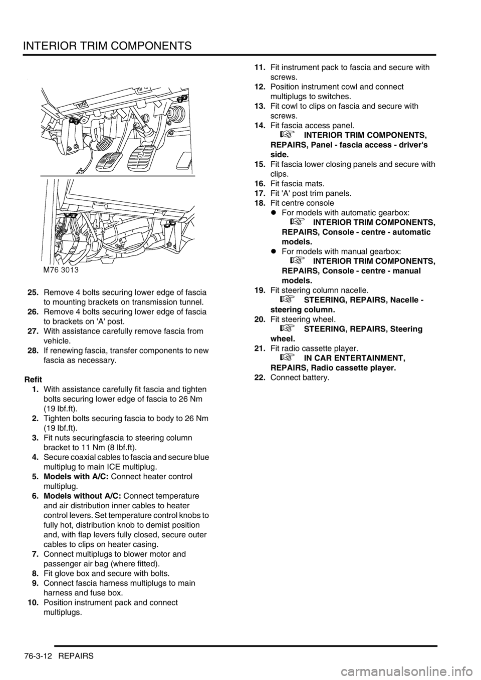
25.Remove 4 bolts securing lower edge of fascia
to mounting brackets on transmission tunnel.
26.Remove 4 bolts securing lower edge of fascia
to brackets on 'A' post.
27.With assistance carefully remove fascia from
vehicle.
28.If renewing fascia, transfer components to new
fascia as necessary.
Refit
1.With assistance carefully fit fascia and tighten
bolts securing lower edge of fascia to 26 Nm
(19 lbf.ft).
2.Tighten bolts securing fascia to body to 26 Nm
(19 lbf.ft).
3.Fit nuts securingfascia to steering column
bracket to 11 Nm (8 lbf.ft).
4.Secure coaxial cables to fascia and secure blue
multiplug to main ICE multiplug.
5. Models with A/C: Connect heater control
multiplug.
6. Models without A/C: Connect temperature
and air distribution inner cables to heater
control levers. Set temperature control knobs to
fully hot, distribution knob to demist position
and, with flap levers fully closed, secure outer
cables to clips on heater casing.
7.Connect multiplugs to blower motor and
passenger air bag (where fitted).
8.Fit glove box and secure with bolts.
9.Connect fascia harness multiplugs to main
harness and fuse box.
10.Position instrument pack and connect
multiplugs.11.Fit instrument pack to fascia and secure with
screws.
12.Position instrument cowl and connect
multiplugs to switches.
13.Fit cowl to clips on fascia and secure with
screws.
14.Fit fascia access panel.
+ INTERIOR TRIM COMPONENTS,
REPAIRS, Panel - fascia access - driver's
side.
15.Fit fascia lower closing panels and secure with
clips.
16.Fit fascia mats.
17.Fit 'A' post trim panels.
18.Fit centre console
lFor models with automatic gearbox:
+ INTERIOR TRIM COMPONENTS,
REPAIRS, Console - centre - automatic
models.
lFor models with manual gearbox:
+ INTERIOR TRIM COMPONENTS,
REPAIRS, Console - centre - manual
models.
19.Fit steering column nacelle.
+ STEERING, REPAIRS, Nacelle -
steering column.
20.Fit steering wheel.
+ STEERING, REPAIRS, Steering
wheel.
21.Fit radio cassette player.
+ IN CAR ENTERTAINMENT,
REPAIRS, Radio cassette player.
22.Connect battery.
Page 1283 of 1672

PANEL REPAIRS
77-2-34 REPAIRS
Refit
1.Fit windscreen side finisher.
+ EXTERIOR FITTINGS, REPAIRS,
Side finisher - windscreen.
2.Fit insulation pad to engine bulkhead.
3.Fit front mud flap.
4.Fit road wheel and tighten nuts to 140 Nm (103
lbf.ft).
5.Fit wiring harness to valance assembly.
6. Models with A/C: Fit A/C pipes to valance
assembly.
7.Fit PAS/ACE reservoir.
8.Fit brake pipes to valance assembly.
9. LHD models: Fit brake servo.
+ BRAKES, REPAIRS, Servo - brake.
10.Fit ABS modulator unit.
+ BRAKES, REPAIRS, Modulator unit
- ABS.
11.Fit front bulkhead assembly.
+ PANEL REPAIRS, REPAIRS, Front
bulkhead assembly.
12.Connect leads/multiplug to alternator.
13.Connect battery leads, negative lead last.
'A' post assembly
In this procedure, the front wing and the valance
outer reinforcement (rear section) are replaced in
conjunction with the 'A' post assembly. The dash side
assembly can also be replaced in this procedure if
required.
Remove
1.Disconnect both battery leads, negative lead
first.
2.Disconnect leads/multiplug from alternator.
3.Remove bonnet.
4.Remove front wing.
+ EXTERIOR FITTINGS, REPAIRS,
Wing - front - up to 03MY.
5.Remove RH or LH front door.
+ DOORS, REPAIRS, Door - front.
6.Remove RH or LH sill finisher.
7.Remove windscreen.
+ SCREENS, REPAIRS, Windscreen.
8. Diesel models: Remove ECM.
+ ENGINE MANAGEMENT SYSTEM -
Td5, REPAIRS, Engine control module
(ECM).
9.Remove RH or LH 'A' post inner finishers and
disconnect speaker multiplug (if fitted).
10.Release sunroof drain tube and position aside.
11.Remove RH or LH front seat.
+ SEATS, REPAIRS, Seat - front.
12. RH side: Remove CD autochanger.
+ IN CAR ENTERTAINMENT,
REPAIRS, CD autochanger.
13.Remove fascia.
+ INTERIOR TRIM COMPONENTS,
REPAIRS, Fascia.
14. Driver's side: Remove steering column
support bracket.
15.Remove relevant wiring from 'A' post.
16.Remove tread plate from front door aperture.
17.Release front carpet and position aside.
18.Remove front door aperture seal.
19.Remove engine bulkhead insulation.