Page 1190 of 1672
SEATS
DESCRIPTION AND OPERATION 76-5-5
Seat switch pack
Each seat switch pack contains two switches representing the seat cushion and the seat squab. The switches provide
the following adjustments:
lSeat fore/ aft.
lCushion front up/ down.
lCushion rear up/ down.
lSquab fore/ aft.
lLumbar inflate.
lLumbar deflate.
The voltage supply to the seat switch pack is from the 40A fuse in the satellite fuse box. A pair of switches controls
the operation of each seat motor, the lumbar pump and the lumbar deflate relay.
Seat fore/ aft motor
The seat fore/ aft motor is a permanent magnet motor coupled to a rack and pinion assembly. Should the motor seize
or stick for 6 seconds or more, an internal thermal cut out switch will trip to remove voltage from the motor. Reset
time for the switch is 35 seconds.
Page 1191 of 1672

SEATS
76-5-6 DESCRIPTION AND OPERATION
Two pins within the seat switch pack control the seat fore/ aft motor. Both pins are normally earthed. Operating the
backward switch applies voltage to that pin while the other pin remains earthed. Operating the forward switch reverses
power and earth to the motor allowing the motor to run in the opposite direction.
Seat cushion front up/ down motor
The seat cushion front up/ down motor is a permanent magnet motor coupled to a rack and pinion assembly. Should
the motor seize or stick for 6 seconds or more an internal thermal cut out switch will trip to remove voltage from the
motor. Reset time for the switch is 35 seconds.
Two pins within the seat switch pack control the seat cushion front up/ down motor. Both pins are normally earthed.
Operating the up switch applies voltage to that pin while the other pin remains earthed. Operating the down switch
reverses power and earth to the motor allowing the motor to run in the opposite direction.
Seat cushion rear up/ down motor
The seat cushion rear up/ down motor is a permanent magnet motor coupled to a rack and pinion assembly. Should
the motor seize or stick for 6 seconds or more, an internal thermal cut out switch will trip to remove voltage from the
motor. Reset time for the switch is 35 seconds.
Two pins within the seat switch pack control the seat cushion rear up/ down motor. Both pins are normally earthed.
Operating the up switch applies voltage to that pin while the other pin remains earthed. Operating the down switch
reverses power and earth to the motor allowing the motor to run in the opposite direction.
Seat squab fore/ aft motor
The squab fore/ aft motor is a permanent magnet motor coupled to a rotary rack and pinion assembly. Should the
motor seize or stick for 6 seconds or more, an internal thermal cut out switch will trip to remove voltage from the motor.
Reset time for the switch is 35 seconds.
Two pins within the seat switch pack control the squab fore/ aft motor. Both pins are normally earthed. Operating the
fore switch applies voltage to that pin while the other pin remains earthed. Operating the aft switch reverses power
and earth to the motor allowing the motor to run in the opposite direction.
Lumbar pump
The lumbar pump inflates a bladder in the squab which provides extra support for the seat occupant. With no load on
the seat it takes approximately 10 seconds to completely inflate the bladder. With a load of 25 kg (55 lb) it takes
approximately 15 seconds to inflate the bladder. A pressure cut off switch in the system will operate at 0.12 to 1.93
bar (1.8 to 28 lbf.in
2). If a problem occurs with the lumbar bladder, e.g. a rupture, the whole lumbar system must be
replaced. The components are not serviceable.
Power comes from the seat switch pack through a 3A fuse in the satellite fuse box. The lumbar pump and the lumbar
deflate solenoid share an earth.
Lumbar deflate solenoid
The lumbar deflate solenoid vents the lumbar bladder to atmosphere to allow air to evacuate the bladder. The average
time to evacuate the bladder with a load of 25 kg (55 lb) is 9 seconds.
Power comes from the seat switch pack through a 3A fuse in the satellite fuse box. The lumbar deflate solenoid and
the lumbar pump share an earth.
Page 1195 of 1672
SEATS
76-5-10 DESCRIPTION AND OPERATION
Heated seat block diagram (electric
seats)
1Passenger compartment fuse box
2Left seat heater switch
3Left seat heater module
4Left seat cushion heater element
5Left seat squab heater element
6Right seat heater switch
7Right seat heater module
8Right seat cushion heater element
9Right seat squab heater element
Page 1196 of 1672

SEATS
DESCRIPTION AND OPERATION 76-5-11
Description - heated seats
Heated seats
The heated seat system is available on both manual seats and electric seats. The electrical sub-system consists of
the following components:
lSeat heater switches.
lSeat heater elements.
lTemperature control unit (if electric seats are fitted).
lTemperature sensor (if electric seats are fitted).
lThermostat (if manual seats are fitted).
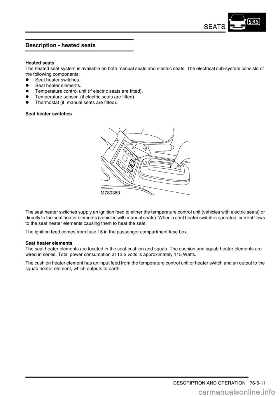
Seat heater switches
The seat heater switches supply an ignition feed to either the temperature control unit (vehicles with electric seats) or
directly to the seat heater elements (vehicles with manual seats). When a seat heater switch is operated, current flows
to the seat heater elements causing them to heat the seat.
The ignition feed comes from fuse 15 in the passenger compartment fuse box.
Seat heater elements
The seat heater elements are located in the seat cushion and squab. The cushion and squab heater elements are
wired in series. Total power consumption at 13.5 volts is approximately 115 Watts.
The cushion heater element has an input feed from the temperature control unit or heater switch and an output to the
squab heater element, which outputs to earth.
Page 1219 of 1672
SUNROOF
76-6-4 DESCRIPTION AND OPERATION
System block diagram
1Passenger compartment fuse box
2BCU
3Sunroof ECU
4Front sunroof switch
5Front sunroof motor and microswitch
6Rear sunroof - front switch
7Rear sunroof isolation switch
8Rear sunroof - rear switch
9Rear sunroof motor and microswitch
Page 1278 of 1672

PANEL REPAIRS
REPAIRS 77-2-29
Valance upper assembly - RH
In this procedure, the front wing and the valance
outer reinforcement are replaced in conjunction with
the RH valance upper assembly.
Remove
1.Disconnect both battery leads, negative lead
first.
2.Disconnect leads/multiplug from alternator.
3.Remove front wing.
+ EXTERIOR FITTINGS, REPAIRS,
Wing - front - up to 03MY.
4.Remove battery.
+ CHARGING AND STARTING,
REPAIRS, Battery.
5.Remove battery tray.
6.Remove fuse box.
7.Release expansion tank from fixings and
position aside.
8.Release harness from valance and position
aside.
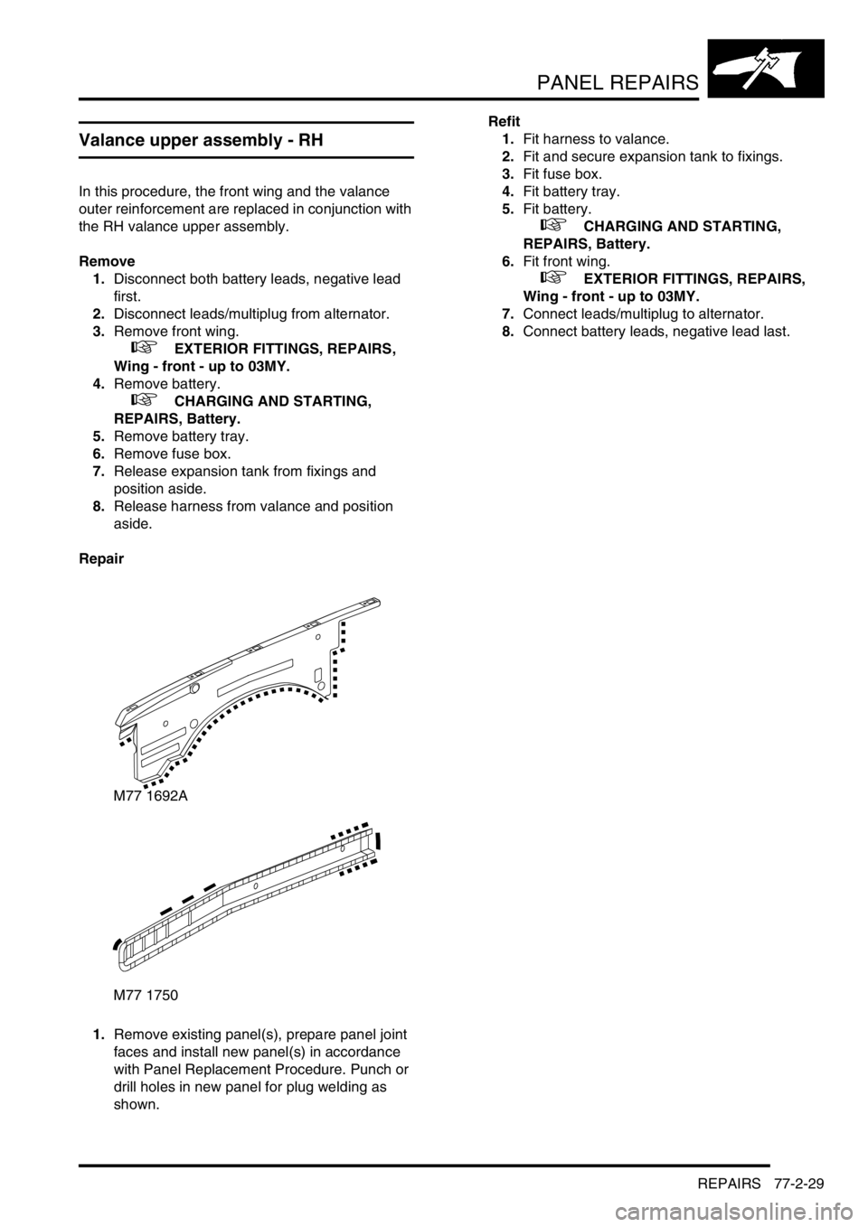
Repair
1.Remove existing panel(s), prepare panel joint
faces and install new panel(s) in accordance
with Panel Replacement Procedure. Punch or
drill holes in new panel for plug welding as
shown.Refit
1.Fit harness to valance.
2.Fit and secure expansion tank to fixings.
3.Fit fuse box.
4.Fit battery tray.
5.Fit battery.
+ CHARGING AND STARTING,
REPAIRS, Battery.
6.Fit front wing.
+ EXTERIOR FITTINGS, REPAIRS,
Wing - front - up to 03MY.
7.Connect leads/multiplug to alternator.
8.Connect battery leads, negative lead last.
M77 1692A
M77 1750
Page 1280 of 1672
PANEL REPAIRS
REPAIRS 77-2-31
5.Fit air filter assembly.
+ ENGINE MANAGEMENT SYSTEM -
Td5, REPAIRS, Air filter assembly.
+ ENGINE MANAGEMENT SYSTEM -
V8, REPAIRS, Air cleaner assembly.
6.Fit front wing.
+ EXTERIOR FITTINGS, REPAIRS,
Wing - front - up to 03MY.
7.Connect leads/multiplug to alternator.
8.Connect battery leads, negative lead last.
Valance upper assembly (front section) -
RH
In this procedure, the front wing and the valance
outer reinforcement (front section) are replaced in
conjunction with the RH valance upper assembly
(front section).
Remove
1.Disconnect both battery leads, negative lead
first.
2.Disconnect leads/multiplug from alternator.
3.Remove front wing.
+ EXTERIOR FITTINGS, REPAIRS,
Wing - front - up to 03MY.
4.Remove battery.
+ CHARGING AND STARTING,
REPAIRS, Battery.
5.Remove battery tray.
6.Remove fuse box.
7.Release expansion tank from fixings and
position aside.
8.Release harness from valance and position
aside.
Page 1281 of 1672

PANEL REPAIRS
77-2-32 REPAIRS
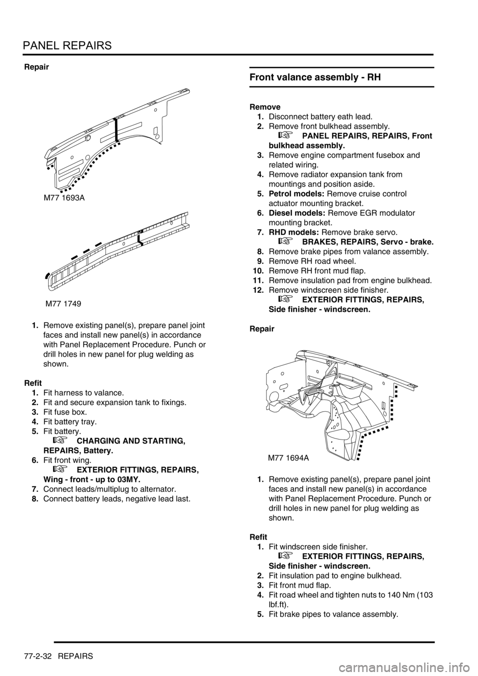
Repair
1.Remove existing panel(s), prepare panel joint
faces and install new panel(s) in accordance
with Panel Replacement Procedure. Punch or
drill holes in new panel for plug welding as
shown.
Refit
1.Fit harness to valance.
2.Fit and secure expansion tank to fixings.
3.Fit fuse box.
4.Fit battery tray.
5.Fit battery.
+ CHARGING AND STARTING,
REPAIRS, Battery.
6.Fit front wing.
+ EXTERIOR FITTINGS, REPAIRS,
Wing - front - up to 03MY.
7.Connect leads/multiplug to alternator.
8.Connect battery leads, negative lead last.
Front valance assembly - RH
Remove
1.Disconnect battery eath lead.
2.Remove front bulkhead assembly.
+ PANEL REPAIRS, REPAIRS, Front
bulkhead assembly.
3.Remove engine compartment fusebox and
related wiring.
4.Remove radiator expansion tank from
mountings and position aside.
5. Petrol models: Remove cruise control
actuator mounting bracket.
6. Diesel models: Remove EGR modulator
mounting bracket.
7. RHD models: Remove brake servo.
+ BRAKES, REPAIRS, Servo - brake.
8.Remove brake pipes from valance assembly.
9.Remove RH road wheel.
10.Remove RH front mud flap.
11.Remove insulation pad from engine bulkhead.
12.Remove windscreen side finisher.
+ EXTERIOR FITTINGS, REPAIRS,
Side finisher - windscreen.
Repair
1.Remove existing panel(s), prepare panel joint
faces and install new panel(s) in accordance
with Panel Replacement Procedure. Punch or
drill holes in new panel for plug welding as
shown.
Refit
1.Fit windscreen side finisher.
+ EXTERIOR FITTINGS, REPAIRS,
Side finisher - windscreen.
2.Fit insulation pad to engine bulkhead.
3.Fit front mud flap.
4.Fit road wheel and tighten nuts to 140 Nm (103
lbf.ft).
5.Fit brake pipes to valance assembly.
M77 1693A
M77 1749
M77 1694A