2002 LAND ROVER DISCOVERY turbo
[x] Cancel search: turboPage 920 of 1672

STEERING
REPAIRS 57-33
21.With assistance remove 2 nuts and bolts
securing RH engine mounting to chassis.
22.Support the engine weight on a jack.
CAUTION: To prevent damage to
components, cushion the jack pad with a
block of wood or hard rubber.
23.Raise the engine sufficiently to allow the
steering box to clear the sump.
24. Models with ACE: Position ACE control arms
to access steering box bolts. 25.With assistance remove 4 bolts securing
steering box and remove steering box.
26.Remove centralising bolt from steering box.
Refit
1.Fit centralising bolt to steering box.
2.With assistance, position steering box, fit bolts
and tighten to 90 Nm (66 lbf.ft).
3.Lower the engine onto its mountings. Fit engine
mounting bolts and tighten to 85 Nm (63 lbf.ft).
4. Models with ACE: Ensure washer is in place
on lower ball joint of anti-roll bar link, then
connect lower ball joint to axle. Tighten nut to
100 Nm (74 lbf.ft).
5.Position drag link, fit nut and tighten to 80 Nm
(59 lbf.ft).
6.Position Panhard rod, fit bolt and nut and
tighten to 230 Nm (170 lbf.ft).
7.Position coolant rail and secure with clips and
bolt.
8.Fit coolant hoses and secure with clips.
9. Models with ACE: Fit and tighten bolt
securing ACE pipes to chassis.
10.Clean PAS pipe ends and 'O' ring recess.
11.Lubricate new 'O' rings for PAS pipes with clean
PAS fluid.
12.Fit 'O' rings to PAS pipes and position pipes in
steering box. Fit PAS pipe bracket and tighten
bolt to 22 Nm (16 lbf.ft).
13.Ensure steering wheel is centralised. Fit
universal joint between steering box and
intermediate shaft and tighten bolts to 25 Nm
(18 lbf.ft).
14.Remove centralising bolt from steering box.
15.Fit intercooler to turbo hose and secure with
clips.
16.Fit road wheel(s) and tighten nuts to 140 Nm
(103 lbf.ft).
17.Remove stand(s) and lower vehicle.
18.Connect battery earth lead.
19.Fit battery cover.
20.Refill cooling system.
+ COOLING SYSTEM - Td5,
ADJUSTMENTS, Drain and refill.
21.Bleed PAS system.
+ STEERING, ADJUSTMENTS,
Hydraulic system - bleed.
22.Centralise steering linkage
+ STEERING, ADJUSTMENTS,
Steering linkage - centralise.
Page 931 of 1672

STEERING
57-44 REPAIRS
14.Position steering column assembly in a vice.
15.Remove 2 screws and remove ignition switch.
16.Remove cable tie and remove multiplug from
ignition switch.
17.Centre punch or drill out steering lock shear
bolts.
18.Remove steering lock
Refit
1.Position lock to steering column assembly and
fit shear bolts. Do not tighten shear bolts at this
stage.
2.Insert starter key, check operation of steering
lock and that key turns freely.
3.Tighten shear bolts fully and shear heads off.
4.Position ignition switch to column, fit and
tighten screws.
5.Position multiplug to switch and secure with
new cable tie.
6.Fit rubber boot to column.
7.Remove column from vice.
8.Position steering to fascia rail fit nuts and
tighten to 22 Nm (16 lbf.ft).
9.Secure harness to column clip.
10.Position rubber grommet.
11.Close access panel and secure turn buckles.
12.Connect ignition switch multiplugs.
13.Position column switch and tighten clamp
screw.
14.Connect column switch multiplugs.
15.Position passive coil, connect multiplug and
illumination bulb.
16.Fit steering column nacelle.
+ STEERING, REPAIRS, Nacelle -
steering column.
17.Fit rotary coupler.
+ RESTRAINT SYSTEMS, REPAIRS,
Rotary coupler.
18.Close fascia lower access panel.
19.Fit steering column intermediate shaft.
+ STEERING, REPAIRS, Shaft -
intermediate and universal joint - steering
column.
Shaft - intermediate and universal joint -
steering column
$% 57.40.22
The intermediate shaft has a red indicator clip
fitted which must be inspected at service, and
after the vehicle has been subject to an impact.
If the clip is not present or is not fully seated
against the clamp plate, a new assembly must be
fitted.
Remove
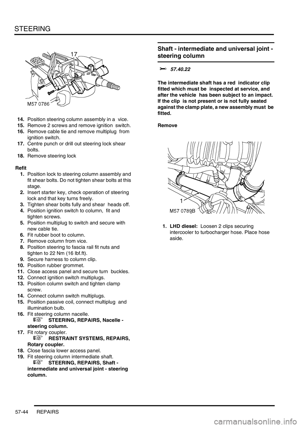
1. LHD diesel: Loosen 2 clips securing
intercooler to turbocharger hose. Place hose
aside.
Page 933 of 1672

STEERING
57-46 REPAIRS
6. Intermediate shaft: Slide the intermediate
shaft upwards, release from the universal joint
and remove intermediate shaft from the
steering column.
7. Universal joint: Slide the intermediate shaft
upwards, release from the universal joint and
remove universal joint from the steering box. Refit
1.Clean and inspect splines for wear and
damage.
2. Intermediate shaft: Locate intermediate shaft
on steering column and engage with universal
joint. Ensure splines are fully engaged and bolt
holes aligned.
3. Universal joint: Locate universal joint on
steering box and engage in intermediate shaft.
Ensure splines are fully engaged and bolt
holes aligned.
4.Fit bolts securing intermediate shaft to
universal joint and tighten to 25 Nm (18 lbf.ft).
5. Intermediate shaft: Fit bolts securing
intermediate shaft to steering column and
tighten to 25 Nm (18 lbf.ft).
6. Universal joint: Fit bolts securing universal
joint to steering box and tighten to 25 Nm (18
lbf.ft).
7. LHD diesel: Connect hose to turbocharger
and intercooler and secure the clips.
8.Fit ignition key, remove steering box
centralising bolt and check that steering wheel
is in the straight ahead position.
Page 983 of 1672

FRONT SUSPENSION
60-44 REPAIRS
Pump - ACE - diesel
$% 60.60.10
CAUTION: The ACE hydraulic system is
extremely sensitive to the ingress of dirt or
debris. The smallest amount could render the
system unserviceable. It is imperative that the
following precautions are taken.
lACE components are thoroughly cleaned
externally before work commences;
lall opened pipe and module ports are
capped immediately;
lall fluid is stored in and administered
through clean containers.
Remove
1.Remove auxiliary drive belt.
+ CHARGING AND STARTING,
REPAIRS, Belt - auxiliary drive.
2.Disconnect multiplugs from mass air flow
sensor and ambient air pressure sensor.
3.Release clips and disconnect mass air flow
sensor from air cleaner.
4.Loosen hose clip, disconnect inlet air hose
from turbo charger and move hose aside. 5.Release ACE/PAS reservoir from bracket and
move aside.
6.Loosen clip and disconnect inlet hose from
intercooler.
7.Position container to catch spillage.
Page 984 of 1672

FRONT SUSPENSION
REPAIRS 60-45
8.Release clip and disconnect suction hose from
ACE pump.
9.Remove banjo bolt and disconnect pressure
pipe from ACE pump. Discard sealing washers.
CAUTION: Always fit plugs to open
connections to prevent contamination.
10.Remove 3 bolts securing ACE pump to
mounting and remove ACE pump.
11.Restrain pulley, remove 3 securing bolts and
remove pulley from ACE pump.Refit
1.Clean mating faces of pulley and ACE pump.
2.Position pulley to ACE pump and fit bolts.
Restrain pulley and tighten bolts to 25 Nm (18
lbf.ft).
3.Clean mating faces of ACE pump and
mounting.
4.Connect suction hose to ACE pump and secure
with clip.
5.Ensure there is sufficient fluid in ACE/PAS
reservoir to prime ACE pump.
6.Position ACE pump below level of ACE/PAS
reservoir, with suction hose uppermost, and
allow fluid from ACE/PAS reservoir to
completely fill ACE pump.
7.Position ACE pump to mounting, fit bolts and
tighten to 25 Nm (18 lbf.ft).
8.Rotate ACE pump clockwise (viewed from
pulley end) until a steady flow of fluid runs from
outlet port.
9.Connect pressure pipe to ACE pump with banjo
bolt and new sealing washers. Tighten banjo
bolt to 28 Nm (21 lbf.ft).
10.Connect hose to intercooler and secure with
clip.
11.Fit ACE/PAS reservoir into mounting bracket.
12.Connect air hose to turbo charger and secure
with clip.
13.Fit mass air flow sensor to air filter and secure
with clips.
14.Connect multiplugs to mass air flow sensor and
ambient air pressure sensor.
15.Fit auxiliary drive belt.
+ CHARGING AND STARTING,
REPAIRS, Belt - auxiliary drive.
16.Renew ACE high pressure filter.
+ FRONT SUSPENSION, REPAIRS,
Filter - high pressure - ACE.
Page 997 of 1672

FRONT SUSPENSION
60-58 REPAIRS
7.Remove 2 screws securing lower half of fan
cowl and remove cowl.
8.Disconnect multiplug from air flow meter.
9.Release clips and remove air flow meter from
air cleaner.
10.Collect 'O' ring. 11.Loosen clip, disconnect air hose from
turbocharger and move hose aside.
12.Release clip and disconnect pressure sensing
hose from turbocharger outlet pipe.
13.Loosen clips securing turbocharger outlet pipe
hoses.
14.Remove turbocharger outlet pipe and hoses as
an assembly.
Page 1000 of 1672

FRONT SUSPENSION
REPAIRS 60-61
7.Fit pipe clamps to pipes, align clamps to
chassis front cross member and fit bolts.
8. Valve block to reservoir pipe: F it pi pe to c li p
on LH chassis member.
9.Fit pipe clamp to pipes, align clamp to
suspension turret and secure with nut.
10.Fit pipe clamp to pipes, align clamp to RH
chassis member and secure with bolt.
11.Align and secure harness to suspension turret.
12.Fit thermostat housing and hoses and secure
hoses with clips.
13.Fit turbocharger outlet pipe and secure hoses
with clips.
14.Connect turbocharger pressure sensing hose
and secure with clip.
15.Fit 'O' ring to air cleaner.
16.Fit air hose to turbocharger and tighten clip.
17.Fit air flow meter to air cleaner and secure with
clips.
18.Connect multiplug to air flow meter.
19.Fit lower half of fan cowl and secure with
screws.
20.Fit viscous fan.
+ COOLING SYSTEM - Td5, REPAIRS,
Fan - viscous.
21.Fit RH splash shield and secure with screws.
22.Fit road wheel.
23.Fit valve block.
+ FRONT SUSPENSION, REPAIRS,
Valve block - ACE.
24.Renew ACE high pressure filter
+ FRONT SUSPENSION, REPAIRS,
Filter - high pressure - ACE.
25.Lower vehicle.
26.Fill cooling system.
+ COOLING SYSTEM - Td5,
ADJUSTMENTS, Drain and refill.
Pipe assembly - valve block to rear
actuator - ACE
$% 60.60.33
CAUTION: The ACE hydraulic system is
extremely sensitive to the ingress of dirt or
debris. The smallest amount could render the
system unserviceable. It is imperative that the
following precautions are taken.
lACE components are thoroughly cleaned
externally before work commences;
lall opened pipe and module ports are
capped immediately;
lall fluid is stored in and administered
through clean containers.
Remove
1.Raise vehicle on a ramp.
2.Position container under valve block to collect
fluid spillage.
3.Remove 2 bolts securing 2 rear pipe clips to
chassis.
Page 1586 of 1672

HARNESSES
REPAIRS 86-7-15
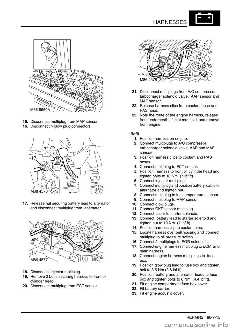
15.Disconnect multiplug from MAP sensor.
16.Disconnect 4 glow plug connectors.
17.Release nut securing battery lead to alternator
and disconnect multiplug from alternator.
18.Disconnect injector multiplug.
19.Remove 2 bolts securing harness to front of
cylinder head.
20.Disconnect multiplug from ECT sensor. 21.Disconnect multiplugs from A/C compressor,
turbocharger solenoid valve, AAP sensor and
MAF sensor.
22.Release harness clips from coolant hose and
PAS hose.
23.Note the route of the engine harness, release
from underneath of inlet manifold and remove
from engine.
Refit
1.Position harness on engine.
2.Connect multiplugs to A/C compressor,
turbocharger solenoid valve, AAP and MAF
sensors.
3.Position harness clips to coolant and PAS
hoses.
4.Connect multiplug to ECT sensor.
5.Position harness to front of cylinder head and
tighten bolts to 10 Nm (7 lbf.ft).
6.Connect injector multiplug.
7.Connect multiplug and position battery cable to
alternator and tighten nut.
8.Connect multiplug to fuel temperature sensor.
9.Connect multiplug to MAP sensor.
10.Connect glow plugs.
11.Connect CKP sensor multiplug.
12.Connect Lucar to starter solenoid.
13.Connect battery lead to starter solenoid and
tighten nut to 10 Nm (7 lbf.ft).
14.Position harness clip to coolant pipe.
15.Locate harness over bell housing and connect
multiplug to oil pressure switch.
16.Connect 2 multiplugs to EGR solenoids.
17.Connect engine harness multiplug to ECM and
main harness.
18.Connect engine harness multiplugs to fuse
box.
19.Position glow plug lead to fuse box and tighten
bolt to 3.5 Nm (2.6 lbf.ft).
20.Position battery and alternator leads to fuse
box and tighten bolts to 6 Nm (4.4 lbf.ft).
21.Fit engine compartment fuse box cover.
22.Fit battery carrier.
23.Fit engine acoustic cover.