Page 781 of 1672

TRANSFER BOX - LT230SE
41-48 OVERHAUL
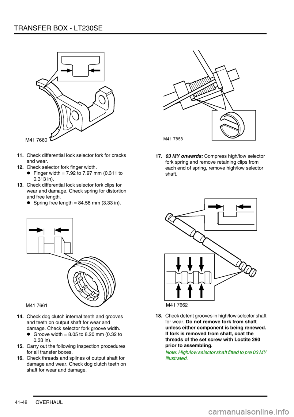
11.Check differential lock selector fork for cracks
and wear.
12.Check selector fork finger width.
lFinger width = 7.92 to 7.97 mm (0.311 to
0.313 in).
13.Check differential lock selector fork clips for
wear and damage. Check spring for distortion
and free length.
lSpring free length = 84.58 mm (3.33 in).
14.Check dog clutch internal teeth and grooves
and teeth on output shaft for wear and
damage. Check selector fork groove width.
lGroove width = 8.05 to 8.20 mm (0.32 to
0.33 in).
15.Carry out the following inspection procedures
for all transfer boxes.
16.Check threads and splines of output shaft for
damage and wear. Check dog clutch teeth on
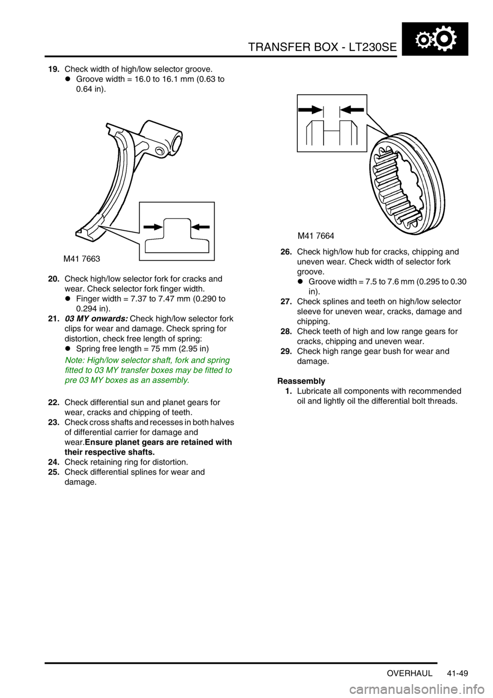
shaft for wear and damage.17.03 MY onwards: Compress high/low selector
fork spring and remove retaining clips from
each end of spring, remove high/low selector
shaft.
18.Check detent grooves in high/low selector shaft
for wear. Do not remove fork from shaft
unless either component is being renewed.
If fork is removed from shaft, coat the
threads of the set screw with Loctite 290
prior to assembling.
Note: High/low selector shaft fitted to pre 03 MY
illustrated.
Page 782 of 1672

TRANSFER BOX - LT230SE
OVERHAUL 41-49
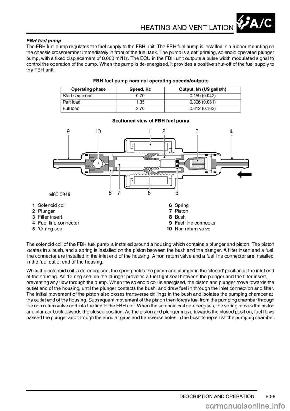
19.Check width of high/low selector groove.
lGroove width = 16.0 to 16.1 mm (0.63 to
0.64 in).
20.Check high/low selector fork for cracks and
wear. Check selector fork finger width.
lFinger width = 7.37 to 7.47 mm (0.290 to
0.294 in).
21.03 MY onwards: Check high/low selector fork
clips for wear and damage. Check spring for
distortion, check free length of spring:
lSpring free length = 75 mm (2.95 in)
Note: High/low selector shaft, fork and spring
fitted to 03 MY transfer boxes may be fitted to
pre 03 MY boxes as an assembly.
22.Check differential sun and planet gears for
wear, cracks and chipping of teeth.
23.Check cross shafts and recesses in both halves
of differential carrier for damage and
wear.Ensure planet gears are retained with
their respective shafts.
24.Check retaining ring for distortion.
25.Check differential splines for wear and
damage.26.Check high/low hub for cracks, chipping and
uneven wear. Check width of selector fork
groove.
lGroove width = 7.5 to 7.6 mm (0.295 to 0.30
in).
27.Check splines and teeth on high/low selector
sleeve for uneven wear, cracks, damage and
chipping.
28.Check teeth of high and low range gears for
cracks, chipping and uneven wear.
29.Check high range gear bush for wear and
damage.
Reassembly
1.Lubricate all components with recommended
oil and lightly oil the differential bolt threads.
Page 1350 of 1672

HEATING AND VENTILATION
DESCRIPTION AND OPERATION 80-9
FBH fuel pump
The FBH fuel pump regulates the fuel supply to the FBH unit. The FBH fuel pump is installed in a rubber mounting on
the chassis crossmember immediately in front of the fuel tank. The pump is a self priming, solenoid operated plunger
pump, with a fixed displacement of 0.063 ml/Hz. The ECU in the FBH unit outputs a pulse width modulated signal to
control the operation of the pump. When the pump is de-energised, it provides a positive shut-off of the fuel supply to
the FBH unit.
FBH fuel pump nominal operating speeds/outputs
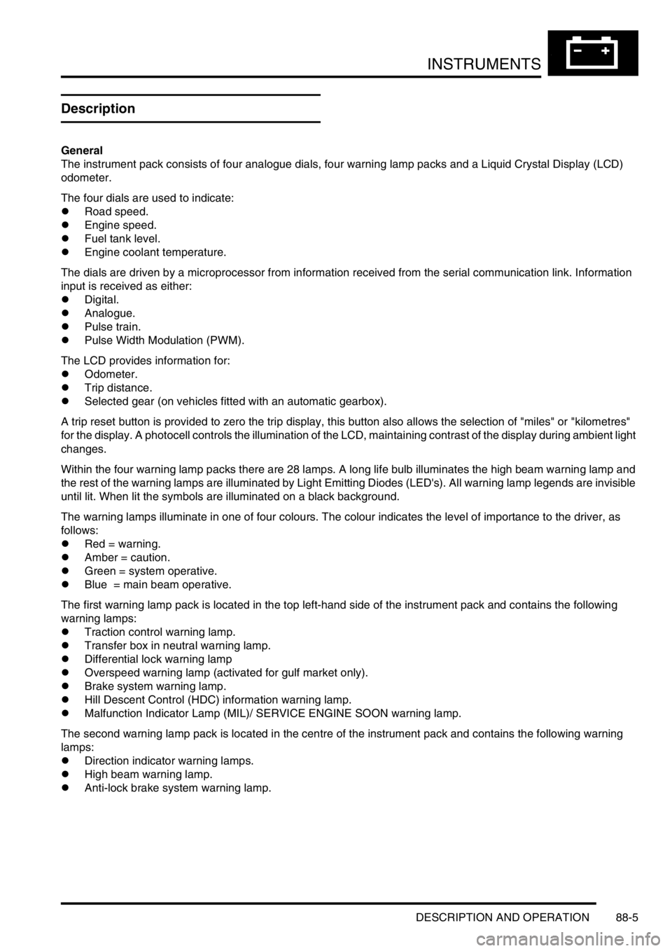
Sectioned view of FBH fuel pump
1Solenoid coil
2Plunger
3Filter insert
4Fuel line connector
5'O' ring seal6Spring
7Piston
8Bush
9Fuel line connector
10Non return valve
The solenoid coil of the FBH fuel pump is installed around a housing which contains a plunger and piston. The piston
locates in a bush, and a spring is installed on the piston between the bush and the plunger. A filter insert and a fuel
line connector are installed in the inlet end of the housing. A non return valve and a fuel line connector are installed
in the fuel outlet end of the housing.
While the solenoid coil is de-energised, the spring holds the piston and plunger in the 'closed' position at the inlet end
of the housing. An 'O' ring seal on the plunger provides a fuel tight seal between the plunger and the filter insert,
preventing any flow through the pump. When the solenoid coil is energised, the piston and plunger move towards the
outlet end of the housing, until the plunger contacts the bush, and draw fuel in through the inlet connection and filter.
The initial movement of the piston also closes transverse drillings in the bush and isolates the pumping chamber at
the outlet end of the housing. Subsequent movement of the piston then forces fuel from the pumping chamber through
the non return valve and into the line to the FBH unit. When the solenoid coil de-energises, the spring moves the piston
and plunger back towards the closed position. As the piston and plunger move towards the closed position, fuel flows
passed the plunger and through the annular gaps and transverse holes in the bush to replenish the pumping chamber.
Operating phase Speed, Hz Output, l/h (US galls/h)
Start sequence 0.70 0.159 (0.042)
Part load 1.35 0.306 (0.081)
Full load 2.70 0.612 (0.163)
Page 1632 of 1672

INSTRUMENTS
DESCRIPTION AND OPERATION 88-5
Description
General
The instrument pack consists of four analogue dials, four warning lamp packs and a Liquid Crystal Display (LCD)
odometer.
The four dials are used to indicate:
lRoad speed.
lEngine speed.
lFuel tank level.
lEngine coolant temperature.
The dials are driven by a microprocessor from information received from the serial communication link. Information
input is received as either:
lDigital.
lAnalogue.
lPulse train.
lPulse Width Modulation (PWM).
The LCD provides information for:
lOdometer.
lTrip distance.
lSelected gear (on vehicles fitted with an automatic gearbox).
A trip reset button is provided to zero the trip display, this button also allows the selection of "miles" or "kilometres"
for the display. A photocell controls the illumination of the LCD, maintaining contrast of the display during ambient light
changes.
Within the four warning lamp packs there are 28 lamps. A long life bulb illuminates the high beam warning lamp and
the rest of the warning lamps are illuminated by Light Emitting Diodes (LED's). All warning lamp legends are invisible
until lit. When lit the symbols are illuminated on a black background.
The warning lamps illuminate in one of four colours. The colour indicates the level of importance to the driver, as
follows:
lRed = warning.
lAmber = caution.
lGreen = system operative.
lBlue = main beam operative.
The first warning lamp pack is located in the top left-hand side of the instrument pack and contains the following
warning lamps:
lTraction control warning lamp.
lTransfer box in neutral warning lamp.
lDifferential lock warning lamp
lOverspeed warning lamp (activated for gulf market only).
lBrake system warning lamp.
lHill Descent Control (HDC) information warning lamp.
lMalfunction Indicator Lamp (MIL)/ SERVICE ENGINE SOON warning lamp.
The second warning lamp pack is located in the centre of the instrument pack and contains the following warning
lamps:
lDirection indicator warning lamps.
lHigh beam warning lamp.
lAnti-lock brake system warning lamp.