2002 LAND ROVER DISCOVERY alternator
[x] Cancel search: alternatorPage 328 of 1672

EMISSION CONTROL - TD5
DESCRIPTION AND OPERATION 17-1-7
The ILT modulator is located on a plate fixed to the inner wing on the RH side of the engine below the EGR modulator.
The modulator is attached to the plate by two through-studs, each with two nuts which secure the modulator assembly
to a rubber mounting which helps to reduce noise. The modulator must be mounted in the vertical orientation with the
two vacuum ports uppermost.
The modulator operation is controlled by a signal from the ECM which determines the required ratio of exhaust gas
to fresh inlet air needed in response to inputs relating to air flow and engine operating and ambient conditions. The
modulator has a green two-pin connector at its base to connect it to the ECM through the engine harness.
The ILT valve modulator features three ports:
lThe top port is identified by a white band and connects to a 'T'-piece in the vacuum line via a small-bore brown
plastic hose where it is connected in parallel with the vacuum source line to the EGR valve modulator. The two
other ports on the 'T'-piece connect vacuum line hoses of black vinyl tubing between the vacuum pump attached
to the alternator and the brake-servo assembly attached to the bulkhead.
lThe middle port is identified by a blue band and connects to the suction port on the ILT valve through a small-
bore blue plastic hose.
lThe lower port is identified by a green band and connects to atmosphere through an in-line filter via a green
plastic hose and a three-way connector positioned in-line between the modulators and the filter. The ILT
modulator hose is connected opposite to the two parallel ports at the three-way connector which connect the vent
lines to the EGR valve modulator and the in-line filter. The other port of the in-line filter vents directly to
atmosphere.
The blue and brown vacuum hoses are protected by corrugated plastic sheaths. The ends of the hoses are fitted with
rubber boots to ensure vacuum tight seals at the component ports.
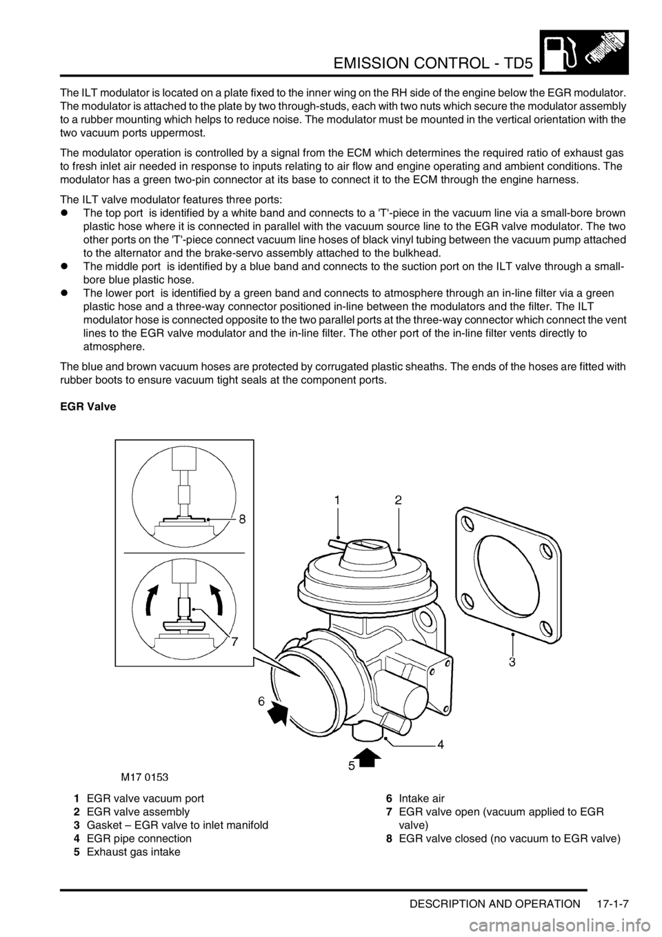
EGR Valve
1EGR valve vacuum port
2EGR valve assembly
3Gasket – EGR valve to inlet manifold
4EGR pipe connection
5Exhaust gas intake6Intake air
7EGR valve open (vacuum applied to EGR
valve)
8EGR valve closed (no vacuum to EGR valve)
Page 489 of 1672

ENGINE MANAGEMENT SYSTEM - V8
18-2-32 DESCRIPTION AND OPERATION
Idle Air Control Valve (IACV) (C0641)
The IACV is located on the side of the air inlet pipe on top of the engine. The IACV is used to maintain good quality
idle speed under all operating conditions.
When an engine is running at idle it is subject to a combination of internal and external loads that can affect idle speed.
These loads include engine friction, water pump, alternator operation, and air conditioning.
The IACV acts as an air bypass valve. The ECM uses the IACV to enable the closed loop idle speed calculation to be
made by the ECM. This calculation regulates the amount of air flow into the engine at idle, therefore compensating
for any internal or external loads that may affect idle speed.
The IACV utilises two coils that use opposing PWM signals to control the position of opening/closing of a rotary valve.
If one of the circuits that supply the PWM signal fails, the ECM closes down the remaining signal preventing the IACV
from working at its maximum/ minimum setting. If this should occur, the IACV automatically resumes a default idle
position. In this condition, the engine idle speed is raised and maintained at 1200 rev/min with no load placed on the
engine.
The idle speed in cold start condition is held at 1200 rev/min in neutral for 20 seconds and ignition timing is retarded
as a catalyst heating strategy. The cold start idle speed and the default idle position give the same engine speed 1200
rev/min, and although they are the same figure they must not be confused with each other as they are set separately
by the ECM.
Note that the rotary valve must not be forced to move by mechanical means. The actuator can not be
serviced; if defective, the entire IACV must be replaced.
Input/Output
The input to the IACV is a 12 volt signal from fuse 2 located in the engine compartment fuse box. The output earth
signal to open and close the actuator is controlled by the ECM as follows:
lIACV (open signal) - via pin 42 of connector C0636 of the ECM
lIACV (closed signal) - via pin 43 of connector C0636 of the ECM
The IACV can fail the following ways or supply incorrect signal:
lActuator faulty.
lRotary valve seized.
lWiring loom fault.
lConnector fault.
lIntake system air leak.
lBlocked actuator port or hoses.
lRestricted or crimped actuator port or hoses.
Page 530 of 1672

ENGINE MANAGEMENT SYSTEM - V8
REPAIRS 18-2-73
5.Remove 2 nuts and release ECM from studs
and location on 'A' post lower panel.
6.Lower ECM into footwell and disconnect 5
multiplugs.
7.Remove ECM.
Refit
1.Position new ECM and connect multiplugs.
2.Fit ECM and secure with nuts.
3.Fit lower trim panel to 'A' post and secure with
fixings.
4.Fit diagnostic socket to closing panel, fit closing
panel and secure with fixings.
5.Connect battery earth lead.
6.Fit battery cover and secure with fixings.
7.Programme ECM and reset adaptions using
TestBook.
Sensor - engine coolant temperature
(ECT)
$% 18.30.10
Remove
1.Release turnbuckles and remove battery cover.
2.Disconnect battery earth lead.
3.Remove auxiliary drive belt.
+ CHARGING AND STARTING,
REPAIRS, Belt - auxiliary drive.
4.Remove 2 bolts securing alternator, release
alternator from support bracket and position
aside.
Page 531 of 1672

ENGINE MANAGEMENT SYSTEM - V8
18-2-74 REPAIRS
5.Disconnect multiplug from ECT sensor.
6.Remove sensor from inlet manifold and discard
sealing washer.
Refit
1.Clean sealant from threads in manifold.
2.Apply Loctite 577 to sensor threads.
3.Fit new sealing washer to ECT sensor and
tighten sensor to 10 Nm (7 lbf.ft).
4.Connect multiplug to ECT sensor.
5.Position alternator, fit bolts and tighten to 45
Nm (33 lbf.ft).
6.Fit auxiliary drive belt.
+ CHARGING AND STARTING,
REPAIRS, Belt - auxiliary drive.
7.Top up cooling system.
8.Connect battery earth lead.
9.Fit battery cover and secure with fixings.
Sensor - crankshaft position (CKP)
$% 18.30.12
Remove
1.Release fixings and remove battery cover.
2.Disconnect battery earth lead.
3.Raise front of vehicle.
WARNING: Do not work on or under a
vehicle supported only by a jack. Always
support the vehicle on safety stands.
4.Release fixings and remove underbelly panel.
5.Release CKP sensor multiplug from bracket.
6.Remove 2 bolts securing CKP sensor heat
shield and position aside.
7.Remove 2 nuts securing CKP sensor, remove
2 spacers, CKP sensor and sensor mounting.
8.Disconnect CKP sensor multiplug from engine
harness.
Refit
1.Ensure all components are clean.
2.Connect CKP sensor multiplug to engine
harness.
3.Fit sensor mounting, CKP sensor, 2 spacers
and tighten CKP sensor retaining nuts to 6 Nm
(5 lbf.ft).
Page 627 of 1672

MANIFOLDS AND EXHAUST SYSTEMS - TD5
30-1-6 REPAIRS
Gasket - inlet manifold
$% 30.15.08
Remove
Note: The following procedure covers engines
fitted with or without an EGR cooler. The EGR
cooler is bolted to the front of the cylinder head.
1.Remove battery cover.
2.Disconnect battery earth lead.
3.Remove 3 bolts and remove engine acoustic
cover.
4.Release retainers and remove upper fan cowl.
5.Disconnect leads from 4 glow plugs and
multiplug from MAP sensor.
6.Remove 4 bolts, release EGR valve from inlet
manifold and discard gasket. 7.Remove 4 bolts securing fuel cooler to inlet
manifold.
8.Remove 2 bolts and remove alternator support
bracket.
9.Remove bolt securing engine dip stick tube to
camshaft carrier.
10.Remove dip stick tube and discard 'O' ring.
Page 628 of 1672

MANIFOLDS AND EXHAUST SYSTEMS - TD5
REPAIRS 30-1-7
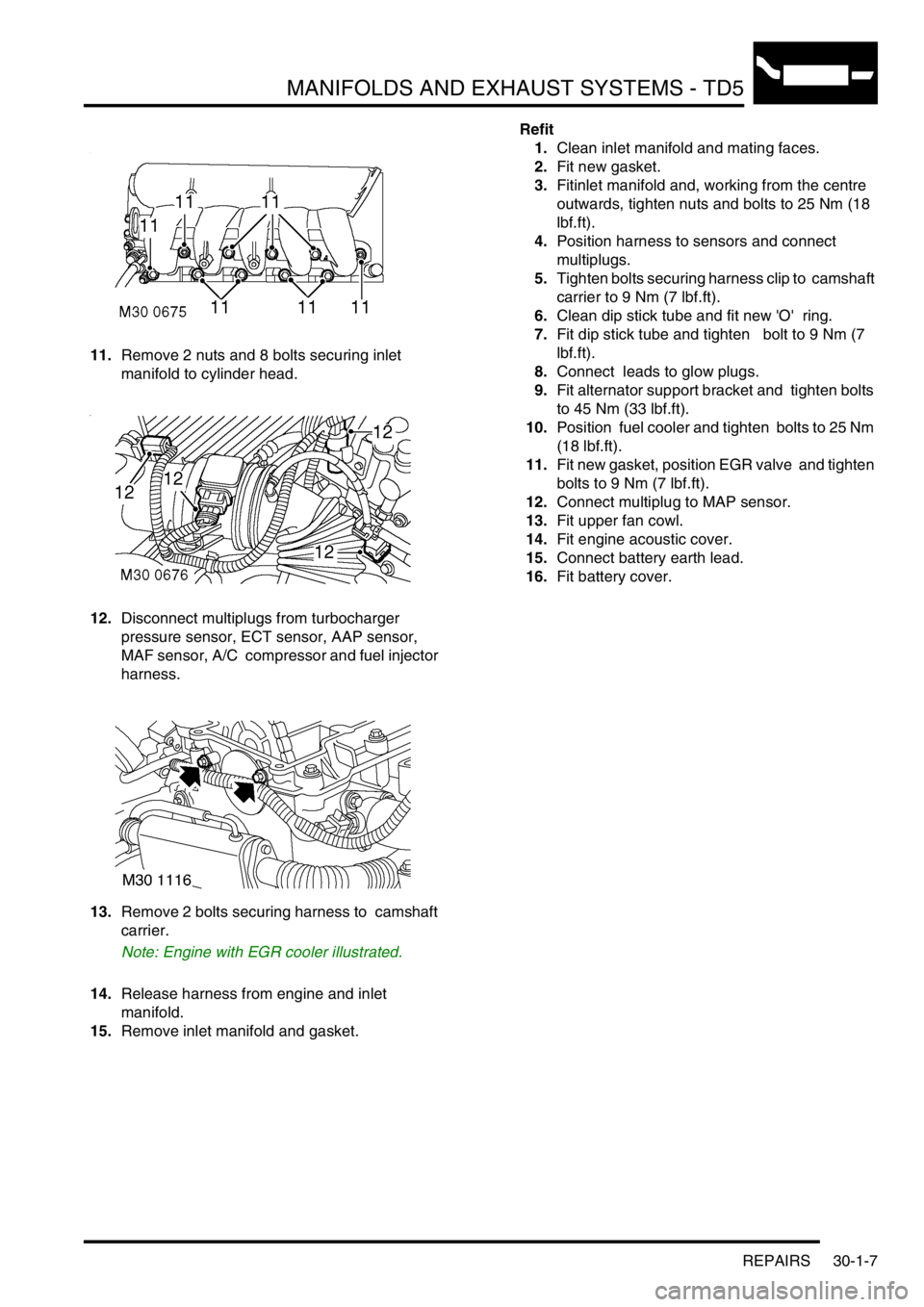
11.Remove 2 nuts and 8 bolts securing inlet
manifold to cylinder head.
12.Disconnect multiplugs from turbocharger
pressure sensor, ECT sensor, AAP sensor,
MAF sensor, A/C compressor and fuel injector
harness.
13.Remove 2 bolts securing harness to camshaft
carrier.
Note: Engine with EGR cooler illustrated.
14.Release harness from engine and inlet
manifold.
15.Remove inlet manifold and gasket. Refit
1.Clean inlet manifold and mating faces.
2.Fit new gasket.
3.Fitinlet manifold and, working from the centre
outwards, tighten nuts and bolts to 25 Nm (18
lbf.ft).
4.Position harness to sensors and connect
multiplugs.
5.Tighten bolts securing harness clip to camshaft
carrier to 9 Nm (7 lbf.ft).
6.Clean dip stick tube and fit new 'O' ring.
7.Fit dip stick tube and tighten bolt to 9 Nm (7
lbf.ft).
8.Connect leads to glow plugs.
9.Fit alternator support bracket and tighten bolts
to 45 Nm (33 lbf.ft).
10.Position fuel cooler and tighten bolts to 25 Nm
(18 lbf.ft).
11.Fit new gasket, position EGR valve and tighten
bolts to 9 Nm (7 lbf.ft).
12.Connect multiplug to MAP sensor.
13.Fit upper fan cowl.
14.Fit engine acoustic cover.
15.Connect battery earth lead.
16.Fit battery cover.
Page 642 of 1672

MANIFOLDS AND EXHAUST SYSTEMS - V8
REPAIRS 30-2-13
5.Remove 3 bolts securing ACE pump, release
pump and position aside.
6.Remove 2 bolts securing alternator and
remove alternator. 7.Remove 3 bolts securing PAS pump pulley and
remove pulley.
8.Remove jockey pulley.
9.Position tray to catch spillage, release PAS
pump high pressure pipe.
CAUTION: Always fit plugs to open
connections to prevent contamination.
10.Remove bolt securing oil cooling pipe and
release bracket from auxiliary housing.
11.Remove two bolts securing PAS pump.
12.Remove 5 bolts and one nut securing auxiliary
housing. Pull housing forward, release PAS
pump and remove housing.
Page 644 of 1672

MANIFOLDS AND EXHAUST SYSTEMS - V8
REPAIRS 30-2-15
Refit
1.Clean old RTV sealant from cylinder head and
cylinder block notches.
2.Clean mating faces of cylinder block, cylinder
head and inlet manifold.
3.Apply RTV sealant to cylinder head and
cylinder block notches.
4.Fit new gasket seals, ensuring ends engage
correctly in notches.
5.Fit new inlet manifold gasket.
6.Position gasket clamps and fit bolts, but do not
tighten at this stage.
7.Position inlet manifold to engine. Fit manifold
bolts and, working in the sequence shown,
tighten bolts initially to 10 Nm (7 lbf.ft) then to
51 Nm (38 lbf.ft).
8.Tighten gasket clamp bolts to 18 Nm (13 lbf.ft).
9.Connect fuel pipe.
10.Clean top hose outlet pipe mating faces.
11.Fit new 'O' ring to outlet pipe.
12.Position outlet pipe, fit bolts and tighten to 22
Nm (16 lbf.ft).
13.Position alternator, fit bolts and tighten to 45
Nm (33 lbf.ft).
14.Position PAS pump to auxiliary housing and
locate housing on engine. Fit bolts and tighten
to 40 Nm (30 lbf.ft).
15.Fit and tighten auxiliary housing nut to 10 Nm (7
lbf.ft).
16.Fit bolts securing PAS pump and tighten to 22
Nm (16 lbf.ft). 17.Position oil cooling pipe bracket fit bolt and
tighten to 22 Nm (16 lbf.ft).
18.Fit and tighten PAS pump high pressure pipe.
19.Position jockey pulley and tighten bolt to 50 Nm
(37 lbf.ft).
20.Clean PAS pump pulley mating faces.
21.Position PAS pump pulley, fit bolts and tighten
to 22 Nm (16 lbf.ft).
22.Clean ACE pump dowels and dowel holes.
23.Position ACE pump, fit bolts and tighten to 22
Nm (16 lbf.ft).
24.Fit auxiliary drive belt.
+ CHARGING AND STARTING,
REPAIRS, Belt - auxiliary drive.
25.Secure injector harness and connect injector
multiplugs.
26.Position top hose and secure clips.
27.Fit rocker covers.
l
+ ENGINE - V8, REPAIRS, Gasket
- rocker cover - LH.
l
+ ENGINE - V8, REPAIRS, Gasket
- rocker cover - RH.
28.Check and top up PAS fluid