2002 LAND ROVER DISCOVERY coolant level
[x] Cancel search: coolant levelPage 615 of 1672

COOLING SYSTEM - V8
26-2-14 ADJUSTMENTS
5.Release top hose from retaining lugs on the fan
cowl, leaving the hose to rest on the lugs.
6.Remove bleed screw from top hose.
l'A' From 03 MY
l'B' Up to 03 MY
7.Unclip the bleed hose from the battery box.
8.Remove expansion tank from its mounting
bracket. Slowly fill the expansion tank with
coolant, approx. 4 litres (7 pt).
9.Raise the expansion tank approx. 20 cm (8 in)
vertically, coolant will drain into the system.
10.Refill the coolant expansion tank until a steady
flow of coolant is emitted from the bleed hole.
11.Fit the bleed screw then, with the expansion
tank still raised, continue filling the system until
the coolant level reaches the base of the
expansion tank filler neck.12.Fit expansion tank filler cap, fit the expansion
tank to its mountings and clip the bleed hose to
the battery box.
13.Refit the top hose into its lugs on the fan cowl.
14.Start and run engine until normal operating
temperature is reached, and check for leaks.
15.Switch off engine and allow to cool.
16.Check for leaks and top-up coolant to cold level
mark on expansion tank
Page 1344 of 1672

HEATING AND VENTILATION
DESCRIPTION AND OPERATION 80-3
Description
General
The heating and ventilation system controls the temperature and distribution of air supplied to the vehicle interior. The
system consists of an air inlet duct, heater assembly, distribution ducts and a control panel. An outlet vent is
incorporated at the rear of the cabin. Some diesel models also incorporate a fuel burning heater (FBH) system in the
engine coolant supply to the heater assembly.
Fresh or recirculated air flows into the heater assembly from the inlet duct. An electrical variable speed blower in the
inlet duct, and/or ram effect, forces the air through the system. Depending on the settings on the control panel, the air
is then heated and supplied through the distribution ducts to fascia and floor level outlets.
Page 1346 of 1672

HEATING AND VENTILATION
DESCRIPTION AND OPERATION 80-5
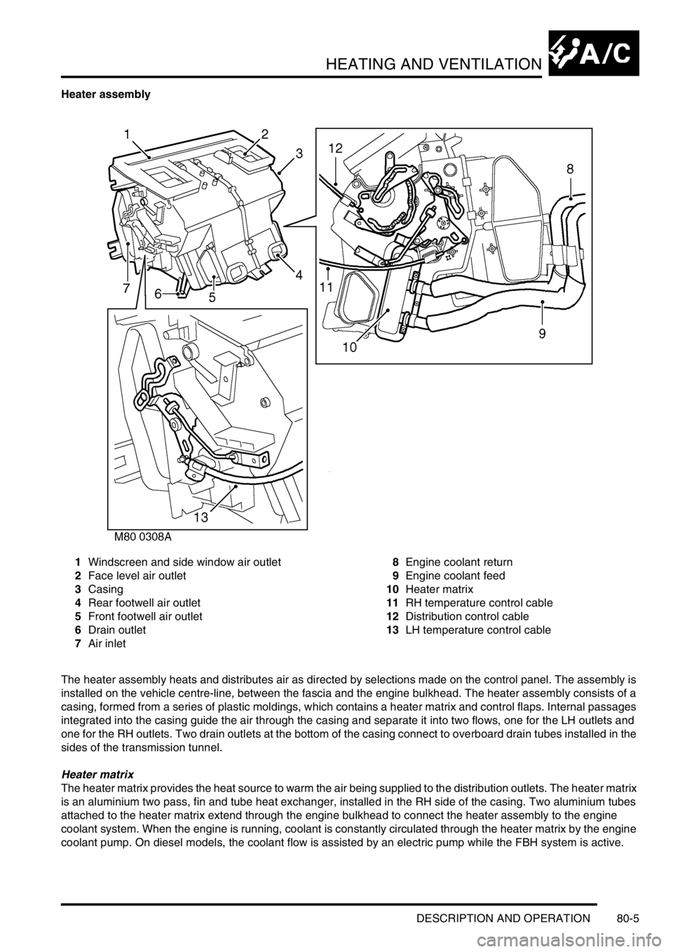
Heater assembly
1Windscreen and side window air outlet
2Face level air outlet
3Casing
4Rear footwell air outlet
5Front footwell air outlet
6Drain outlet
7Air inlet8Engine coolant return
9Engine coolant feed
10Heater matrix
11RH temperature control cable
12Distribution control cable
13LH temperature control cable
The heater assembly heats and distributes air as directed by selections made on the control panel. The assembly is
installed on the vehicle centre-line, between the fascia and the engine bulkhead. The heater assembly consists of a
casing, formed from a series of plastic moldings, which contains a heater matrix and control flaps. Internal passages
integrated into the casing guide the air through the casing and separate it into two flows, one for the LH outlets and
one for the RH outlets. Two drain outlets at the bottom of the casing connect to overboard drain tubes installed in the
sides of the transmission tunnel.
Heater matrix
The heater matrix provides the heat source to warm the air being supplied to the distribution outlets. The heater matrix
is an aluminium two pass, fin and tube heat exchanger, installed in the RH side of the casing. Two aluminium tubes
attached to the heater matrix extend through the engine bulkhead to connect the heater assembly to the engine
coolant system. When the engine is running, coolant is constantly circulated through the heater matrix by the engine
coolant pump. On diesel models, the coolant flow is assisted by an electric pump while the FBH system is active.
Page 1349 of 1672

HEATING AND VENTILATION
80-8DESCRIPTION AND OPERATION
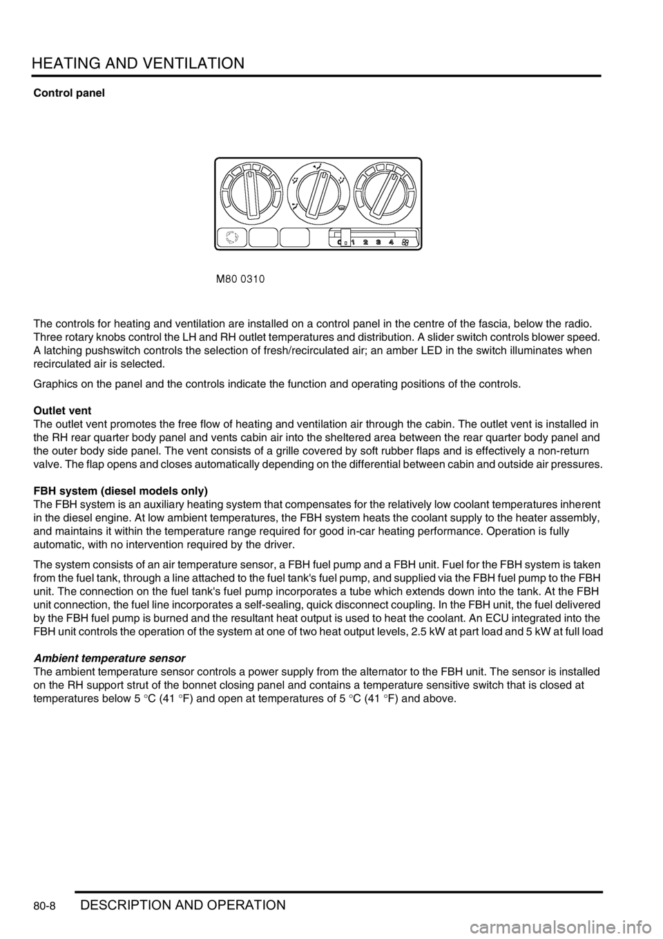
Control panel
The controls for heating and ventilation are installed on a control panel in the centre of the fascia, below the radio.
Three rotary knobs control the LH and RH outlet temperatures and distribution. A slider switch controls blower speed.
A latching pushswitch controls the selection of fresh/recirculated air; an amber LED in the switch illuminates when
recirculated air is selected.
Graphics on the panel and the controls indicate the function and operating positions of the controls.
Outlet vent
The outlet vent promotes the free flow of heating and ventilation air through the cabin. The outlet vent is installed in
the RH rear quarter body panel and vents cabin air into the sheltered area between the rear quarter body panel and
the outer body side panel. The vent consists of a grille covered by soft rubber flaps and is effectively a non-return
valve. The flap opens and closes automatically depending on the differential between cabin and outside air pressures.
FBH system (diesel models only)
The FBH system is an auxiliary heating system that compensates for the relatively low coolant temperatures inherent
in the diesel engine. At low ambient temperatures, the FBH system heats the coolant supply to the heater assembly,
and maintains it within the temperature range required for good in-car heating performance. Operation is fully
automatic, with no intervention required by the driver.
The system consists of an air temperature sensor, a FBH fuel pump and a FBH unit. Fuel for the FBH system is taken
from the fuel tank, through a line attached to the fuel tank's fuel pump, and supplied via the FBH fuel pump to the FBH
unit. The connection on the fuel tank's fuel pump incorporates a tube which extends down into the tank. At the FBH
unit connection, the fuel line incorporates a self-sealing, quick disconnect coupling. In the FBH unit, the fuel delivered
by the FBH fuel pump is burned and the resultant heat output is used to heat the coolant. An ECU integrated into the
FBH unit controls the operation of the system at one of two heat output levels, 2.5 kW at part load and 5 kW at full load
Ambient temperature sensor
The ambient temperature sensor controls a power supply from the alternator to the FBH unit. The sensor is installed
on the RH support strut of the bonnet closing panel and contains a temperature sensitive switch that is closed at
temperatures below 5
°C (41 °F) and open at temperatures of 5 °C (41 °F) and above.
Page 1391 of 1672

AIR CONDITIONING
82-18DESCRIPTION AND OPERATION
Operation
General
While the system is on, the ATC ECU operates the refrigerant system and the inlet air, blower speed, air temperature
and air distribution functions to produce the conditions requested on the control panel. When the system is first
switched on, the ATC ECU resumes the control outputs in use when the system was last switched off. If conditions
have changed, or a different mode is selected to switch the system on, the control outputs are then changed to
produce the required new settings.
The system operates in automatic, economy and defrost modes, with manual overrides of the inlet air source, blower
speed and air distribution. The air temperature is automatically controlled in all operating modes.
In the automatic mode, the ATC ECU operates the system to warm-up or cool down the cabin to establish and
maintain the temperature selections on the control panel, while directing the air to those outlets most comfortable for
the occupant(s). If a difference between the LH and RH temperature selections causes a conflict of the required inlet
air source, blower speed or air distribution settings, priority is given to achieving the temperature requested on the
driver's side of the control panel.
The ATC ECU enters the economy mode when the refrigerant compressor is selected off while the system is in the
automatic mode, which reduces the load on the engine. Economy mode operation is similar to the automatic mode,
but without the ability to cool the cabin if the ambient temperature is higher than the temperature selections made on
the control panel, or to dehumidify the air in the cabin.
In the defrost mode, the ATC ECU sets the inlet air source to fresh air, the blower to maximum speed, the air
distribution to windscreen and side windows, and outputs signals to the BCU to operate the rear window heater and
(where fitted) the windscreen heater. The BCU starts or, if the heaters are already on, resets the heater timers and
energises the rear window and windscreen heaters for a complete on cycle.
Air temperature control
To determine the amount of heat or cooling required by the cabin, the ATC ECU uses the sensor inputs and the
temperatures selected on the control panel to calculate target air outlet temperatures for the driver's and the front
passenger's side of the heater assembly. The ATC ECU then signals the servo motors controlling the respective blend
flaps in the heater assembly to move to the flaps to the appropriate position. The target temperatures are constantly
updated and, in the automatic mode, also used in further calculations to determine the inlet air source, the blower
speed and the air distribution.
Inlet air control
The inlet air source is automatically controlled while the system is off or on. While the system is on, the inlet air source
can also be manually controlled to give timed recirculated air or latched recirculated air.
While the system is off, the ATC ECU uses vehicle speed to determine the inlet air source. With the vehicle at rest,
the inlet air source is set to recirculated air. When vehicle speed reaches 17.5 mph (28 km/h), the inlet air source
changes to fresh air. The inlet air source then remains at fresh air until the vehicle speed decreases to 5 mph (8 km/
h), when it returns to recirculated air.
While the system is on, the ATC ECU uses the LH and RH temperature selections, vehicle speed, ambient air
temperature and coolant temperature to determine the inlet air source. In the automatic mode:
lIf one temperature selection is set to LO and one is set to a specific temperature or HI, the inlet air is set to
recirculated air.
lIf one temperature selection is set to HI and one is set to a specific temperature or HI, the inlet air is set to fresh
air.
lWhen specific LH and RH temperature selections are set, the inlet air source remains at fresh air except when
the air distribution function is set to face level only or face level and footwell outlets. If the air distribution function
is set to face level only or face level and footwell outlets, at 56 mph (90 km/h) the inlet air source changes to
recirculated air (to exclude ram effect, which becomes excessive at speed). When the vehicle speed decreases
to 37.5 mph (60 km/h), the inlet air source returns to fresh air.
Page 1392 of 1672

AIR CONDITIONING
DESCRIPTION AND OPERATION 82-19
In the defrost mode, the inlet air source is set to fresh air except at low ambient air and coolant temperatures. If, within
5 minutes of the ignition being switched on, the vehicle speed is less than 5 mph (8 km/h) while the external air
temperature is
−16 °C (3 °F) or less and the heater coolant temperature is −10 °C (14 °F) or less, then the inlet air
source is automatically set to the timed recirculated air mode. The timed recirculated air mode is cancelled
immediately the vehicle speed reaches 8 km/h or more .
Timed recirculated air
The timed recirculated air mode sets the inlet air source to recirculated air for 5
± 1 minutes, after which it automatically
reverts to fresh air. Timed recirculated air can be manually selected:
lIn the automatic mode, by pressing the fresh/recirculated air switch for 1.5 seconds or more; the audible warning
sounds twice.
lIn the economy or defrost modes, by pressing the fresh/recirculated air switch for less than 1.5 seconds; the
audible warning sounds once.
Latched recirculated air
The inlet air source can be latched to recirculated air:
lIn the automatic mode, by pressing the fresh/recirculated air switch for less than 1.5 seconds; the audible
warning sounds once.
lIn the economy or defrost modes, by pressing the fresh/recirculated air switch for 1.5 seconds or more; the
audible warning sounds twice.
Blower control
The ATC ECU operates a blower relay, power transistor and power relay to run the blower at one of 31 stepped
speeds. All speed steps are available in the automatic modes of blower control. In the manual mode, speed steps 3,
10, 16, 22 and 31 are used to provide slow, three intermediate and fast blower speeds. The ATC ECU energises the
blower relay and modulates the power transistor to operate the blower for speed steps 1 to 30. For speed step 31, the
ATC ECU energises the power relay, which switches the earth side of the blower motor direct to earth, bypassing the
power transistor.
In the automatic, economy and defrost modes, blower speed is corrected for vehicle speed to compensate for the
increase in ram effect on the inlet air as the vehicle speed increases. Correction begins at approximately 50 km/h,
when blower speed is progressively decreased as vehicle speed increases, until a maximum decrease of 13 steps
occurs at 123 km/h. Similarly, blower speed increases as vehicle speed decreases down to approximately 50 km/h.
In the automatic and economy modes, if the LH or RH temperature is set to LO or HI, the blower runs at maximum
speed with correction only for vehicle speed. If both the LH and RH outlet air temperatures are set to a specific
temperature, blower speed corrections are added to compensate for the heater coolant temperature, external air
temperature, and the solar load acting on the vehicle:
lDuring warm-up, the blower speed is set to 3 while the heater coolant temperature is below approximately 20
°C
(68
°F). From approximately 20 °C (68 °F), the blower speed is progressively increased as the coolant
temperature increases, until maximum speed is set at approximately 50
°C (122 °F).
lDuring cool down, blower speed is set to 3, for 5 seconds after the system is switched on. Over the following 6
seconds, the blower speed is progressively increased up to maximum speed.
lAs the temperature in the cabin approaches the selected temperatures, blower speed is progressively reduced
until, once the selected temperatures have been established, blower speed stabilises at approximately 6.
lSolar heating correction is employed when air distribution is set to face level or to face and footwells. The
correction progressively increases the blower speed, up to a maximum of 9 steps, with increasing values of solar
heating.
Page 1394 of 1672

AIR CONDITIONING
DESCRIPTION AND OPERATION 82-21
Diagnostics
The ATC ECU performs a diagnostic check each time the ignition is switched on. To avoid nuisance fault indications
at low light levels, the sunlight sensor is omitted from the diagnostic check. If a fault is detected, the audible warning
sounds three times and the AUTO window on the control panel display flashes for 20 seconds. The ATC ECU then
reverts to normal control but uses a default value or strategy for the detected fault. Faults are identified by performing
a manual diagnostic check of the system.
A manual diagnostic check includes a check of the sunlight sensor, and is initiated by pressing and holding the AUTO
switch and the air distribution switch, then turning the ignition switch from off to on. The audible warning sounds once
and the indications on the control panel display illuminate. FC is shown in the LH temperature window and the results
of the check are shown as a two digit fault code in the RH temperature window. If a fault is detected, the audible
warning sounds three times and the AUTO window on the display flashes on and off for 20 seconds. If more than one
fault is detected, the fault codes cycle in numerical order, at 1 Hz. The audible warning sounds as each fault code is
shown. In low light conditions, to avoid false sunlight sensor fault indications, the sunlight sensor should be illuminated
with a strong light source.
Diagnostic fault codes and fault descriptions
Code Component Fault Default value/strategy
00 - No fault found -
11 In-car temperature sensor Open or short circuit 25°C (77°F)
12 Ambient temperature sensor Open or short circuit 10°C (50°F)
Cooling fan permanently on
Display shows "- -" if external
air temperature selected
13 Thermistor Open or short circuit 0°C (32°F)
14 Heater coolant temperature sensor Open or short circuit 70°C (158°F)
21 Sunlight sensor, left output Open or short circuit No solar heating correction
22 Sunlight sensor, right output Open or short circuit No solar heating correction
31 LH temperature servo motor Open or short circuit
Motor or flap mechanism seizedServo motor locked in position
32 RH temperature servo motor Open or short circuit
Motor or flap mechanism seizedServo motor locked in position
33 Distribution servo motor Open or short circuit
Motor or flap mechanism seizedServo motor locked in position
Page 1628 of 1672

INSTRUMENTS
DESCRIPTION AND OPERATION 88-1
INS TRUMENTS DESCRIPTION AND OPERAT ION
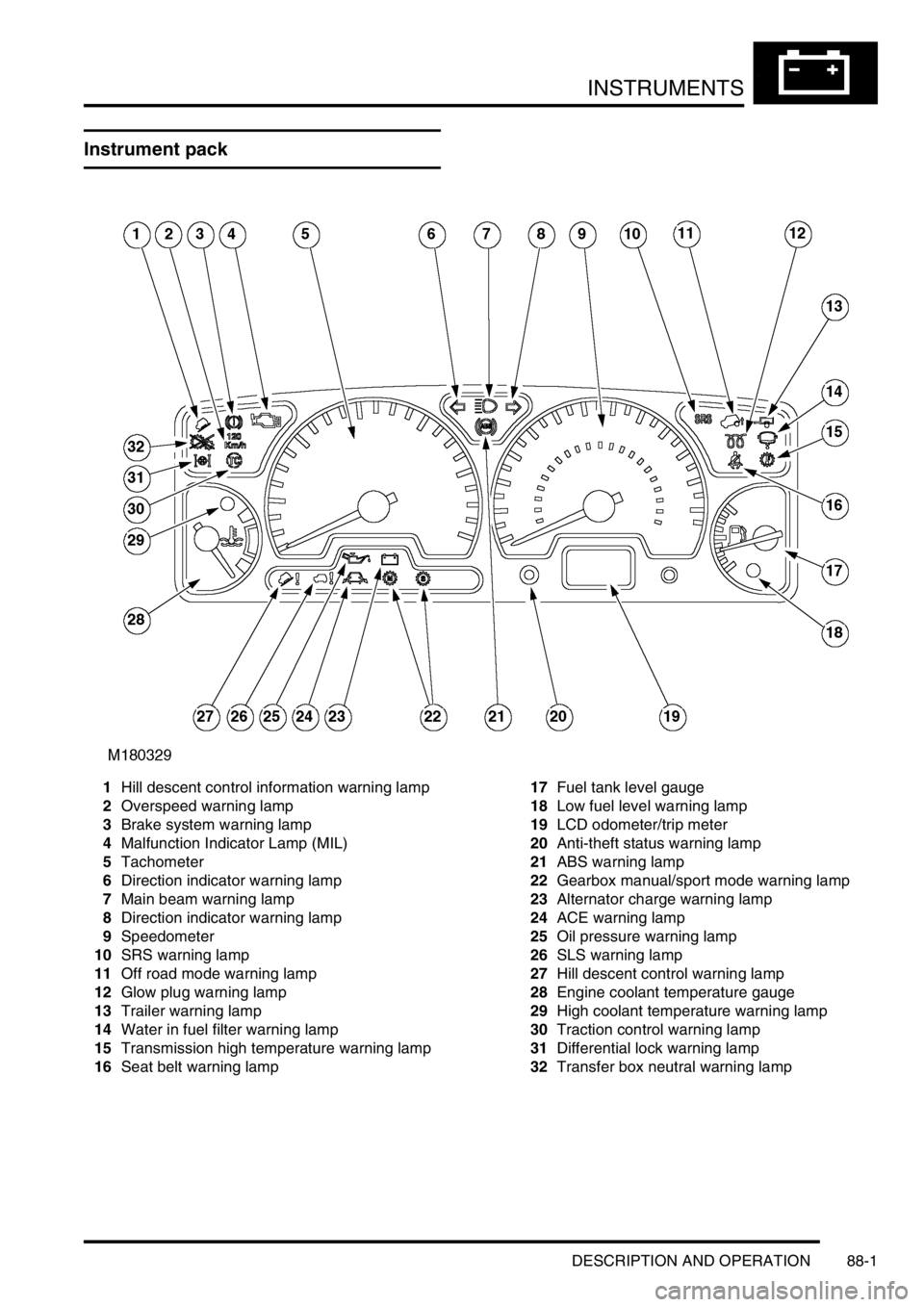
Instrument pack
1Hill descent control information warning lamp
2Overspeed warning lamp
3Brake system warning lamp
4Malfunction Indicator Lamp (MIL)
5Tachometer
6Direction indicator warning lamp
7Main beam warning lamp
8Direction indicator warning lamp
9Speedometer
10SRS warning lamp
11Off road mode warning lamp
12Glow plug warning lamp
13Trailer warning lamp
14Water in fuel filter warning lamp
15Transmission high temperature warning lamp
16Seat belt warning lamp17Fuel tank level gauge
18Low fuel level warning lamp
19LCD odometer/trip meter
20Anti-theft status warning lamp
21ABS warning lamp
22Gearbox manual/sport mode warning lamp
23Alternator charge warning lamp
24ACE warning lamp
25Oil pressure warning lamp
26SLS warning lamp
27Hill descent control warning lamp
28Engine coolant temperature gauge
29High coolant temperature warning lamp
30Traction control warning lamp
31Differential lock warning lamp
32Transfer box neutral warning lamp