Page 821 of 1672

AUTOMATIC GEARBOX - ZF4HP22 - 24
44-24 REPAIRS
Selector indicator
$% 44.15.10
Remove
1.Remove knob from gear lever.
2.Release selector panel from centre console.
3.Disconnect multiplug from selector panel and
remove panel.
Refit
1.Position selector panel and connect multiplug.
2.Secure selector panel to console.
3.Fit gear lever knob.
Switch - starter inhibitor
$% 44.15.19
Remove
1. Diesel models: Remove exhaust front pipe.
+ MANIFOLDS AND EXHAUST
SYSTEMS - Td5, REPAIRS, Pipe - front.
2.Move the selector lever to position 'P'.
3.Remove nut securing selector lever to gearbox
selector shaft and release lever.
4.Remove 2 bolts securing inhibitor switch to
gearbox.
5.Release multiplug from gearbox bracket.
6.Release inhibitor switch from selector shaft.
7.Disconnect switch multiplug and remove
switch.
Refit
1.Ensure 'P' is selected by rotating selector shaft
fully clockwise.
2.Engage 'N' by rotating selector shaft 2 detents
anti-clockwise.
3.Position inhibitor switch to selector shaft,
connect multiplug and secure multiplug to
gearbox bracket.
4.Engage switch to selector shaft, and fit but do
not tighten retaining bolts.
Page 982 of 1672

FRONT SUSPENSION
REPAIRS 60-43
3.Position container to catch spillage.
4.Release clip on pump suction hose and
disconnect hose.
CAUTION: Always fit plugs to open
connections to prevent contamination.
5.Remove banjo bolt and disconnect pressure
pipe from ACE pump. Discard sealing washers.
CAUTION: Always fit plugs to open
connections to prevent contamination.
6.Remove 3 bolts securing ACE pump to
mounting and remove ACE pump.
7.Restrain pulley, remove 3 securing bolts and
remove pulley from ACE pump. Refit
1.Clean mating faces of pulley and ACE pump.
2.Position pulley to ACE pump and fit bolts.
Restrain pulley and tighten bolts to 25 Nm (18
lbf.ft).
3.Clean mating faces of ACE pump and
mounting.
4.Connect suction hose to ACE pump and secure
with clip.
5.Ensure there is sufficient fluid in ACE/PAS
reservoir to prime ACE pump.
6.Position ACE pump below level of ACE/PAS
reservoir, with suction hose uppermost, and
allow fluid from ACE/PAS reservoir to
completely fill ACE pump.
7.Position ACE pump to mounting, fit bolts and
tighten to 25 Nm (18 lbf.ft).
8.Rotate ACE pump clockwise (viewed from
pulley end) until a steady flow of fluid runs from
outlet port.
9.Connect pressure pipe to ACE pump with banjo
bolt and new sealing washers. Tighten banjo
bolt to 28 Nm (21 lbf.ft).
10.Position air intake hose and secure clips.
11.Fit auxiliary drive belt.
+ CHARGING AND STARTING,
REPAIRS, Belt - auxiliary drive.
12.Renew ACE high pressure filter.
+ FRONT SUSPENSION, REPAIRS,
Filter - high pressure - ACE.
Page 984 of 1672

FRONT SUSPENSION
REPAIRS 60-45
8.Release clip and disconnect suction hose from
ACE pump.
9.Remove banjo bolt and disconnect pressure
pipe from ACE pump. Discard sealing washers.
CAUTION: Always fit plugs to open
connections to prevent contamination.
10.Remove 3 bolts securing ACE pump to
mounting and remove ACE pump.
11.Restrain pulley, remove 3 securing bolts and
remove pulley from ACE pump.Refit
1.Clean mating faces of pulley and ACE pump.
2.Position pulley to ACE pump and fit bolts.
Restrain pulley and tighten bolts to 25 Nm (18
lbf.ft).
3.Clean mating faces of ACE pump and
mounting.
4.Connect suction hose to ACE pump and secure
with clip.
5.Ensure there is sufficient fluid in ACE/PAS
reservoir to prime ACE pump.
6.Position ACE pump below level of ACE/PAS
reservoir, with suction hose uppermost, and
allow fluid from ACE/PAS reservoir to
completely fill ACE pump.
7.Position ACE pump to mounting, fit bolts and
tighten to 25 Nm (18 lbf.ft).
8.Rotate ACE pump clockwise (viewed from
pulley end) until a steady flow of fluid runs from
outlet port.
9.Connect pressure pipe to ACE pump with banjo
bolt and new sealing washers. Tighten banjo
bolt to 28 Nm (21 lbf.ft).
10.Connect hose to intercooler and secure with
clip.
11.Fit ACE/PAS reservoir into mounting bracket.
12.Connect air hose to turbo charger and secure
with clip.
13.Fit mass air flow sensor to air filter and secure
with clips.
14.Connect multiplugs to mass air flow sensor and
ambient air pressure sensor.
15.Fit auxiliary drive belt.
+ CHARGING AND STARTING,
REPAIRS, Belt - auxiliary drive.
16.Renew ACE high pressure filter.
+ FRONT SUSPENSION, REPAIRS,
Filter - high pressure - ACE.
Page 1074 of 1672

BRAKES
ADJUSTMENTS 70-29
ADJUST ME NTS
Handbrake
$% 70.45.09
Check
1.Apply the handbrake lever 3 notches on the
ratchet. The handbrake should be fully
operational.
2.If the handbrake is not fully operational, the
brake shoes and/or the handbrake cable need
adjusting.
Adjust
1.Raise rear of vehicle.
WARNING: Do not work on or under a
vehicle supported only by a jack. Always
support the vehicle on safety stands.
2.Ensure handbrake lever is fully released.
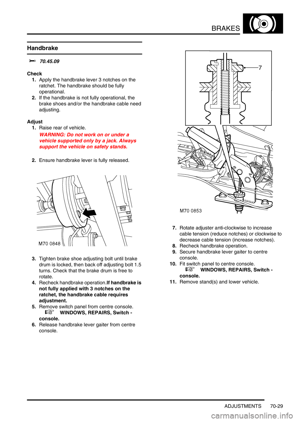
3.Tighten brake shoe adjusting bolt until brake
drum is locked, then back off adjusting bolt 1.5
turns. Check that the brake drum is free to
rotate.
4.Recheck handbrake operation.If handbrake is
not fully applied with 3 notches on the
ratchet, the handbrake cable requires
adjustment.
5.Remove switch panel from centre console.
+ WINDOWS, REPAIRS, Switch -
console.
6.Release handbrake lever gaiter from centre
console.7.Rotate adjuster anti-clockwise to increase
cable tension (reduce notches) or clockwise to
decrease cable tension (increase notches).
8.Recheck handbrake operation.
9.Secure handbrake lever gaiter to centre
console.
10.Fit switch panel to centre console.
+ WINDOWS, REPAIRS, Switch -
console.
11.Remove stand(s) and lower vehicle.
Page 1168 of 1672
INTERIOR TRIM COMPONENTS
REPAIRS 76-3-15
Louvre panel assembly - centre fascia
$% 76.46.42
Remove
1.Remove radio cassette player from fascia.
+ IN CAR ENTERTAINMENT,
REPAIRS, Radio cassette player.
2.Carefully release and remove radio DIN socket
from louvre panel.
3.Remove screw cover from radio aperture.
4.Remove drink tray assembly.
+ INTERIOR TRIM COMPONENTS,
REPAIRS, Drink tray assembly - centre
fascia.
5.Carefully release clock assembly from louvre
panel.
6.Disconnect multiplugs from clock and door
locking switch. Remove clock assembly.7.Carefully release switch pack from louvre
panel.
8.Disconnect multiplugs from switches and
remove switch pack.
9. Models without A/C: Carefully remove blower
speed and heater control knobs.
10. Models without A/C: Remove 2 screws
securing heater control panel graphic plate and
remove graphic plate.
Page 1169 of 1672

INTERIOR TRIM COMPONENTS
76-3-16 REPAIRS
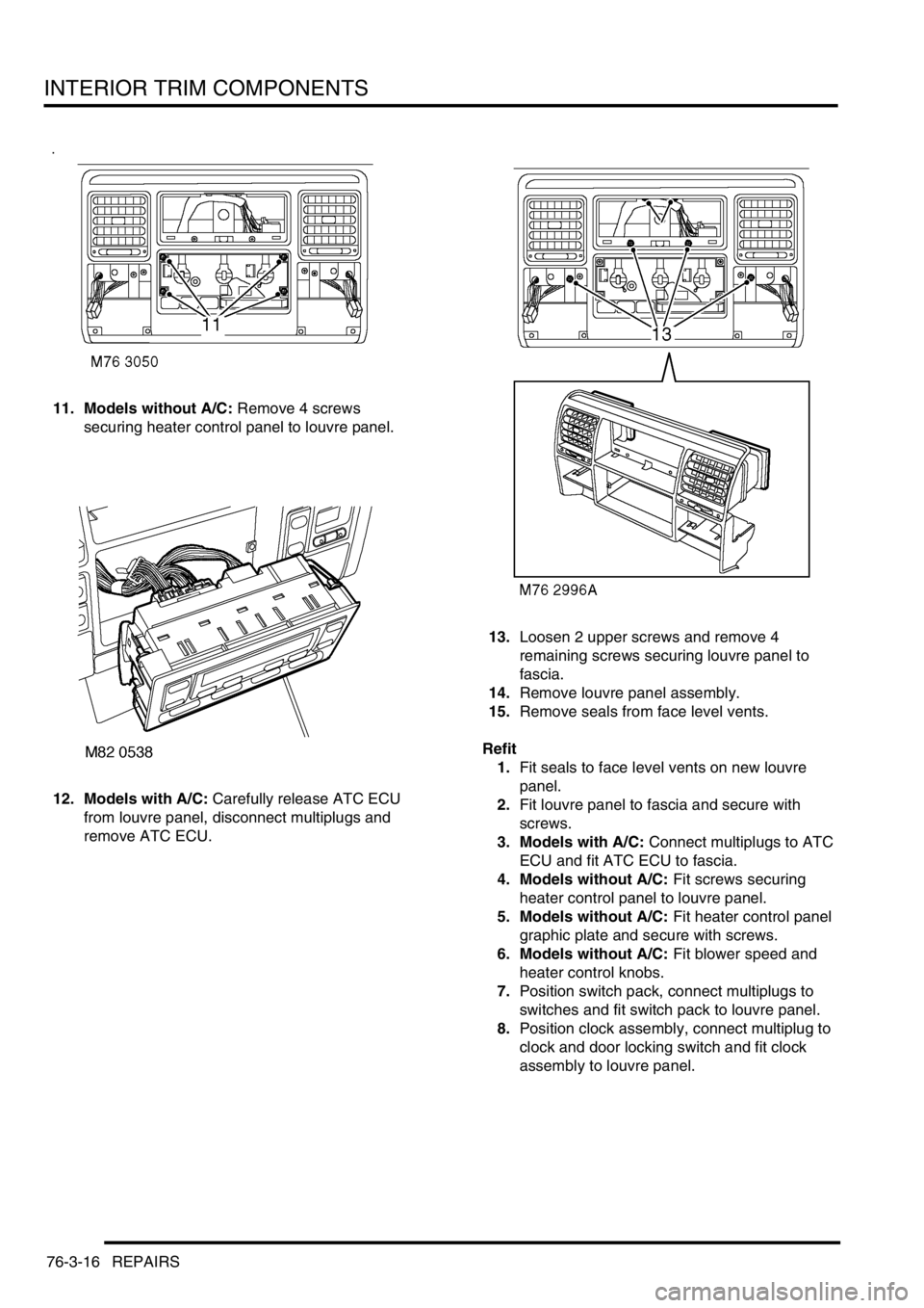
11. Models without A/C: Remove 4 screws
securing heater control panel to louvre panel.
12. Models with A/C: Carefully release ATC ECU
from louvre panel, disconnect multiplugs and
remove ATC ECU.13.Loosen 2 upper screws and remove 4
remaining screws securing louvre panel to
fascia.
14.Remove louvre panel assembly.
15.Remove seals from face level vents.
Refit
1.Fit seals to face level vents on new louvre
panel.
2.Fit louvre panel to fascia and secure with
screws.
3. Models with A/C: Connect multiplugs to ATC
ECU and fit ATC ECU to fascia.
4. Models without A/C: Fit screws securing
heater control panel to louvre panel.
5. Models without A/C: Fit heater control panel
graphic plate and secure with screws.
6. Models without A/C: Fit blower speed and
heater control knobs.
7.Position switch pack, connect multiplugs to
switches and fit switch pack to louvre panel.
8.Position clock assembly, connect multiplug to
clock and door locking switch and fit clock
assembly to louvre panel.
Page 1210 of 1672
SEATS
REPAIRS 76-5-25
Cover - squab - front seat
$% 78.90.08/81
Remove
1.Remove front seat.
+ SEATS, REPAIRS, Seat - front.
2.Place seat on a suitable work bench.
3.Tighten arm rest adjuster fully clockwise and
remove screw cover.
4.Remove screw securing arm rest to seat and
remove arm rest.
5.Remove 2 screws securing outer edge trim
casing to seat frame.
6.Remove trim casing.
7.Release inner edge of trim casing from seat
frame.
8.Remove trim casing. 9.Position seat upside down on table.
10.Release clip securing lower edge of squab
cover to seat frame.
11.Remove 2 clips securing either end of cover to
squab frame.
12.Position seat in upright position.
13.Raise headrest to maximum height.
14.Turn both guides through 90
°.
15.Remove headrest from seat.
16.Remove screws securing grab handles to seat
frame and remove grab handles.
Page 1452 of 1672

CHARGING AND STARTING
REPAIRS 86-1-3
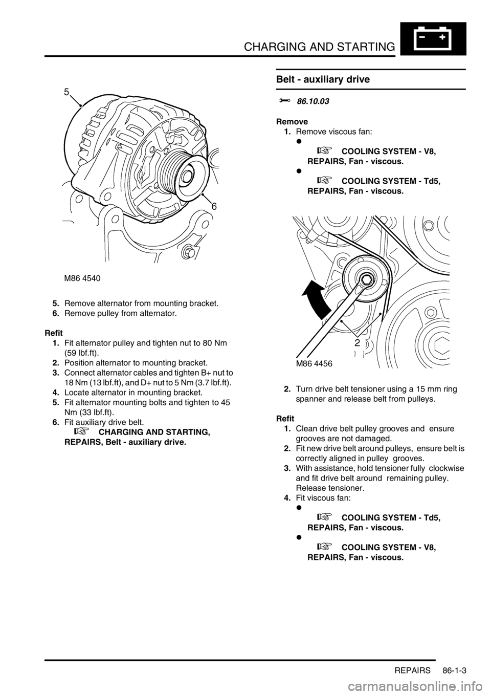
5.Remove alternator from mounting bracket.
6.Remove pulley from alternator.
Refit
1.Fit alternator pulley and tighten nut to 80 Nm
(59 lbf.ft).
2.Position alternator to mounting bracket.
3.Connect alternator cables and tighten B+ nut to
18 Nm (13 lbf.ft), and D+ nut to 5 Nm (3.7 lbf.ft).
4.Locate alternator in mounting bracket.
5.Fit alternator mounting bolts and tighten to 45
Nm (33 lbf.ft).
6.Fit auxiliary drive belt.
+ CHARGING AND STARTING,
REPAIRS, Belt - auxiliary drive.
Belt - auxiliary drive
$% 86.10.03
Remove
1.Remove viscous fan:
l
+ COOLING SYSTEM - V8,
REPAIRS, Fan - viscous.
l
+ COOLING SYSTEM - Td5,
REPAIRS, Fan - viscous.
2.Turn drive belt tensioner using a 15 mm ring
spanner and release belt from pulleys.
Refit
1.Clean drive belt pulley grooves and ensure
grooves are not damaged.
2.Fit new drive belt around pulleys, ensure belt is
correctly aligned in pulley grooves.
3.With assistance, hold tensioner fully clockwise
and fit drive belt around remaining pulley.
Release tensioner.
4.Fit viscous fan:
l
+ COOLING SYSTEM - Td5,
REPAIRS, Fan - viscous.
l
+ COOLING SYSTEM - V8,
REPAIRS, Fan - viscous.