Page 112 of 1672
MAINTENANCE
PROCEDURES 10-3
Seats and seat belts
Check
Front seat
Rear seat rear fixings
Rear seat front fixings
1.Check seat frames are secured to floor and
show no signs of movement.2.Check operation of seat slide and tilt
mechanisms, ensuring there is no excessive
play between seat cushion and seat back.
3.Fully extract seat belt and allow it to return
under its own recoil mechanism. Repeat for
other belts.
4. Check entire length of seat belt webbing for
signs of fraying or damage. Repeat for other
belts.
Page 113 of 1672
MAINTENANCE
10-4 PROCEDURES
5. Check security of seat belt upper mountings.
6. Check for correct operation of seat belt height
adjusters.
7.Check security of seat belt buckle mountings.
8.Connect each belt to the correct buckle, check
seat buckle and tongue are secure. Release
seat belt buckle and check for correct
operation.9.Check tightness of accessible seat belt fixings.
10.Check tightness of accessible seat belt
mountings.
Page 120 of 1672
MAINTENANCE
PROCEDURES 10-11
Air cleaner - V8 engine
Replace
1.Replace air cleaner element.
+ ENGINE MANAGEMENT SYSTEM -
V8, REPAIRS, Element - air filter.
Clean
1.Clean the drain hole in filter casing.
Air cleaner and dump valve - diesel
engine
Replace/clean
1.Replace air cleaner element.
+ ENGINE MANAGEMENT SYSTEM -
Td5, REPAIRS, Element - air filter.
2.Remove all dirt from dump valve.
Auxiliary drive belt
Check
TD5 auxiliary belt
V8 auxiliary belt
1Tensioner pulley
2Alternator
3A/C compressor
4ACE pump
5Idler pulley - V8 only
6PAS pump
7Viscous fan pulley
8Crankshaft pulley
9Idler pulley - V8 only
1.Check auxiliary drive belt for signs of splits,
fraying, oil contamination and wear.
Page 121 of 1672
MAINTENANCE
10-12 PROCEDURES
Auxiliary drive belt - V8 engine
1.Replace auxiliary drive belt.
+ CHARGING AND STARTING,
REPAIRS, Belt - auxiliary drive.
Auxiliary drive belt - diesel engine
Replace
1.Replace auxiliary drive belt.
+ CHARGING AND STARTING,
REPAIRS, Belt - auxiliary drive.
Fluid reservoirs
Check/top-up — Brake/Clutch reservoir
1.Check fluid level in brake/clutch fluid reservoirs.
2.Clean area around filler cap, remove cap.
3.Top-up if necessary to correct level on reservoir
using recommended fluid.
+ CAPACITIES, FLUIDS AND
LUBRICANTS, Fluids.
4.Fit filler cap.
Check/top-up — PAS/ACE reservoirs
1.Check fluid level in PAS and ACE fluid
reservoirs.
2.Clean area around filler cap, remove cap.
3.Top-up if necessary to correct level on reservoir
using recommended fluid.
+ CAPACITIES, FLUIDS AND
LUBRICANTS, Fluids.
4.Fit filler cap.
Page 137 of 1672

MAINTENANCE
10-28 PROCEDURES
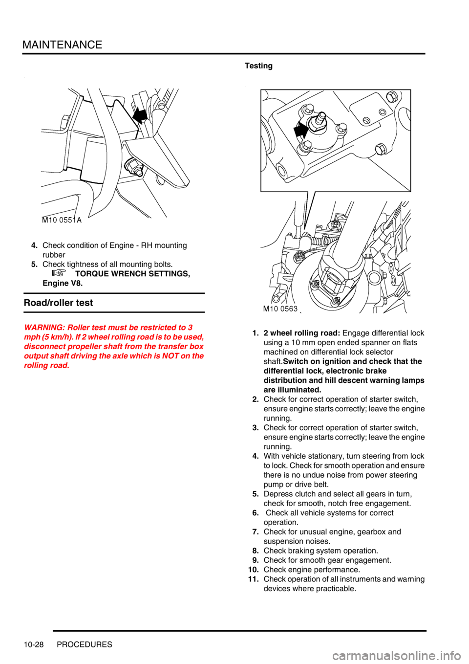
4.Check condition of Engine - RH mounting
rubber
5.Check tightness of all mounting bolts.
+ TORQUE WRENCH SETTINGS,
Engine V8.
Road/roller test
WARNING: Roller test must be restricted to 3
mph (5 km/h). If 2 wheel rolling road is to be used,
disconnect propeller shaft from the transfer box
output shaft driving the axle which is NOT on the
rolling road.Testing
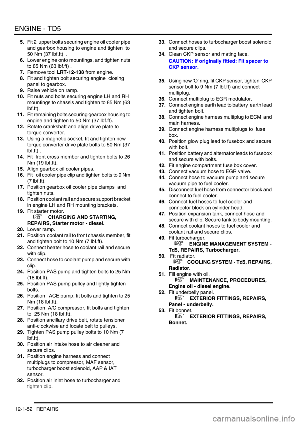
1. 2 wheel rolling road: Engage differential lock
using a 10 mm open ended spanner on flats
machined on differential lock selector
shaft.Switch on ignition and check that the
differential lock, electronic brake
distribution and hill descent warning lamps
are illuminated.
2.Check for correct operation of starter switch,
ensure engine starts correctly; leave the engine
running.
3.Check for correct operation of starter switch,
ensure engine starts correctly; leave the engine
running.
4.With vehicle stationary, turn steering from lock
to lock. Check for smooth operation and ensure
there is no undue noise from power steering
pump or drive belt.
5.Depress clutch and select all gears in turn,
check for smooth, notch free engagement.
6. Check all vehicle systems for correct
operation.
7.Check for unusual engine, gearbox and
suspension noises.
8.Check braking system operation.
9.Check for smooth gear engagement.
10.Check engine performance.
11.Check operation of all instruments and warning
devices where practicable.
Page 176 of 1672

ENGINE - TD5
REPAIRS 12-1-37
REPAIRS
Pulley - crankshaft
$% 12.21.01
Remove
1.Remove fixings and underbelly panel.
2.Remove radiator.
+ COOLING SYSTEM - Td5, REPAIRS,
Radiator.
3.Using a 15 mm ring spanner, release the
auxiliary drive belt tensioner.
4.Remove auxiliary drive belt.
5.Remove 3 bolts and remove crankshaft TV
damper.
6.Position tool LRT-51-003 to crankshaft pulley
and secure with 2 bolts.
7.Remove and discard crankshaft pulley bolt.
Remove crankshaft pulley.
8.Remove 2 bolts and remove tool LRT-51-003
Refit
1.Position new crankshaft pulley to vice.
2.Remove 3 bolts and remove TV damper from
new crankshaft pulley.
3.Using a lint free cloth, thoroughly clean oil seal
recess and the running surface on crankshaft
pulley.
4.Fit crankshaft pulley. 5.Fit tool LRT-51-003 to crankshaft pulley and
secure with 2 bolts.
6.Fit new crankshaft pulley bolt and tighten to
460 Nm (340 lbf.ft), using a torque multiplier.
7.Remove 2 bolts and remove tool LRT-51-003
from crankshaft pulley.
8.Fit TV damper to crankshaft pulley and tighten
– TV damper bolts to 80 Nm (59 lbf.ft) .
9.Fit auxiliary drive belt to pulleys.
10.Fit radiator.
+ COOLING SYSTEM - Td5, REPAIRS,
Radiator.
11.Fit underbelly panel and secure with fixings.
Page 188 of 1672
ENGINE - TD5
REPAIRS 12-1-49
20.Disconnect multiplug from CKP sensor.
21.Remove bolt securing CKP sensor to gearbox
housing and discard 'O' ring.
CAUTION: If fitted: Retain CKP sensor.
22.Loosen clip securing air inlet hose to
turbocharger and remove hose.
23.Disconnect multiplugs from compressor, MAF
sensor, turbocharger boost solenoid valve,
AAP & IAT sensor.
24.Release clip and disconnect hose from
turbocharger boost solenoid valve. 25.Loosen bolts securing PAS pulley.
26.Rotate ancillary drive belt tensioner anti-
clockwise, release and remove drive belt.
27.Release clips and remove air intake hose from
air cleaner.
28.Remove 4 bolts and move compressor aside.
29.Remove 3 bolts and move ACE pump aside.
30.Remove 3 bolts and remove PAS pump pulley.
31.Remove 4 bolts and move PAS pump aside.
Page 191 of 1672

ENGINE - TD5
12-1-52 REPAIRS
5.Fit 2 upper bolts securing engine oil cooler pipe
and gearbox housing to engine and tighten to
50 Nm (37 lbf.ft) .
6.Lower engine onto mountings, and tighten nuts
to 85 Nm (63 lbf.ft) .
7.Remove tool LRT-12-138 from engine.
8.Fit and tighten bolt securing engine closing
panel to gearbox.
9.Raise vehicle on ramp.
10.Fit nuts and bolts securing engine LH and RH
mountings to chassis and tighten to 85 Nm (63
lbf.ft).
11.Fit remaining bolts securing gearbox housing to
engine and tighten to 50 Nm (37 lbf.ft).
12.Rotate crankshaft and align drive plate to
torque converter.
13.Using a magnetic socket, fit and tighten new
torque converter drive plate bolts to 50 Nm (37
lbf.ft) .
14.Fit front cross member and tighten bolts to 26
Nm (19 lbf.ft).
15.Align gearbox oil cooler pipes.
16.Fit oil cooler pipe clip and tighten bolts to 9 Nm
(7 lbf.ft).
17.Position gearbox oil cooler pipe clamps and
tighten nuts.
18.Position coolant rail and secure support bracket
in engine LH and RH mounting brackets.
19.Fit starter motor.
+ CHARGING AND STARTING,
REPAIRS, Starter motor - diesel.
20.Lower ramp.
21.Position coolant rail to front chassis member, fit
and tighten bolt to 10 Nm (7 lbf.ft).
22.Connect heater hose to coolant rail and secure
with clip.
23.Connect hose to coolant pump and secure with
clip.
24.Position PAS pump and tighten bolts to 25 Nm
(18 lbf.ft).
25.Position PAS pump pulley and lightly tighten
bolts.
26.Position ACE pump, fit bolts and tighten to 25
Nm (18 lbf.ft).
27.Position A/C compressor, fit bolts and tighten
to 25 Nm (18 lbf.ft).
28.Position ancillary drive belt, rotate tensioner
anti-clockwise and locate belt to pulleys.
29.Tighten PAS pump pulley bolts to 10 Nm (7
lbf.ft).
30.Position air intake hose to air cleaner and
secure clips.
31.Position engine harness and connect
multiplugs to compressor, MAF sensor,
turbocharger boost solenoid, AAP & IAT
sensor.
32.Position air inlet hose to turbocharger and
tighten clip. 33.Connect hoses to turbocharger boost solenoid
and secure clips.
34.Clean CKP sensor and mating face.
CAUTION: If originally fitted: Fit spacer to
CKP sensor.
35.Using new 'O' ring, fit CKP sensor, tighten CKP
sensor bolt to 9 Nm (7 lbf.ft) and connect
multiplug.
36.Connect multiplug to EGR modulator.
37.Connect engine earth lead to battery earth lead
and tighten bolt.
38.Connect engine harness multiplug to ECM and
main harness.
39.Connect engine harness multiplugs to fuse
box.
40.Position glow plug lead to fusebox and secure
with bolt.
41.Position battery and alternator leads to fusebox
and secure with bolts.
42.Fit engine compartment fuse box cover.
43.Connect vacuum hose to EGR valve.
44.Connect hose to vacuum pump and secure
vacuum pipe to fuel cooler.
45.Disconnect fuel hose from connector block and
connect to fuel cooler.
46.Connect fuel hoses to fuel cooler and
connector block on cylinder head.
47.Position expansion tank, connect hose and
secure with clip. Secure tank to body mounting.
48.Connect coolant hoses to fuel cooler and
coolant rail and secure clips.
49.Fit turbocharger.
+ ENGINE MANAGEMENT SYSTEM -
Td5, REPAIRS, Turbocharger.
50. Fit radiator.
+ COOLING SYSTEM - Td5, REPAIRS,
Radiator.
51.Fill engine with oil.
+ MAINTENANCE, PROCEDURES,
Engine oil - diesel engine.
52.Fit underbelly panel.
+ EXTERIOR FITTINGS, REPAIRS,
Panel - underbelly.
53.Fit bonnet.
+ EXTERIOR FITTINGS, REPAIRS,
Bonnet.