Page 103 of 1672

LIFTING AND TOWING
08-2
Reverse procedure when removing vehicle from
stands.
Hydraulic ramps
Use only a 'drive on' type ramp which supports a
vehicle by it's own road wheels. If a 'wheel free'
condition is required, use a 'drive on' ramp
incorporating a 'wheel free' system that supports
under axle casings. Alternatively, place vehicle on a
firm, flat floor and support on axle stands.
TOWING
Towing
The vehicle has permanent four wheel drive. The
following towing instructions must be adhered
to:
Towing on 4 wheels with driver
Turn ignition key to position '1' to release steering
lock.
Select neutral in main gearbox and transfer gearbox.
Secure tow rope, chain or cable to towing eye.
Release the handbrake.
The brake servo and power assisted steering
system will not be functional without the engine
running. Greater pedal pressure will be required
to apply the brakes, the steering system will
require greater effort to turn the front road
wheels. The vehicle tow connection should be
used only in normal road conditions, 'snatch'
recovery should be avoided.Suspended tow
To prevent vehicle damage, front or rear
propeller shaft MUST BE removed, dependent
upon which axle is being trailed.
Mark propeller shaft drive flanges at transfer box and
axles with identification lines to enable the propeller
shaft to be refitted in its original position.
Remove the propeller shaft fixings, remove the shaft
from the vehicle.
If the front axle is to be trailed turn ignition key to
position '1' to release steering lock.
The steering wheel and/or linkage must be
secured in a straight ahead position. DO NOT use
the steering lock mechanism for this purpose.
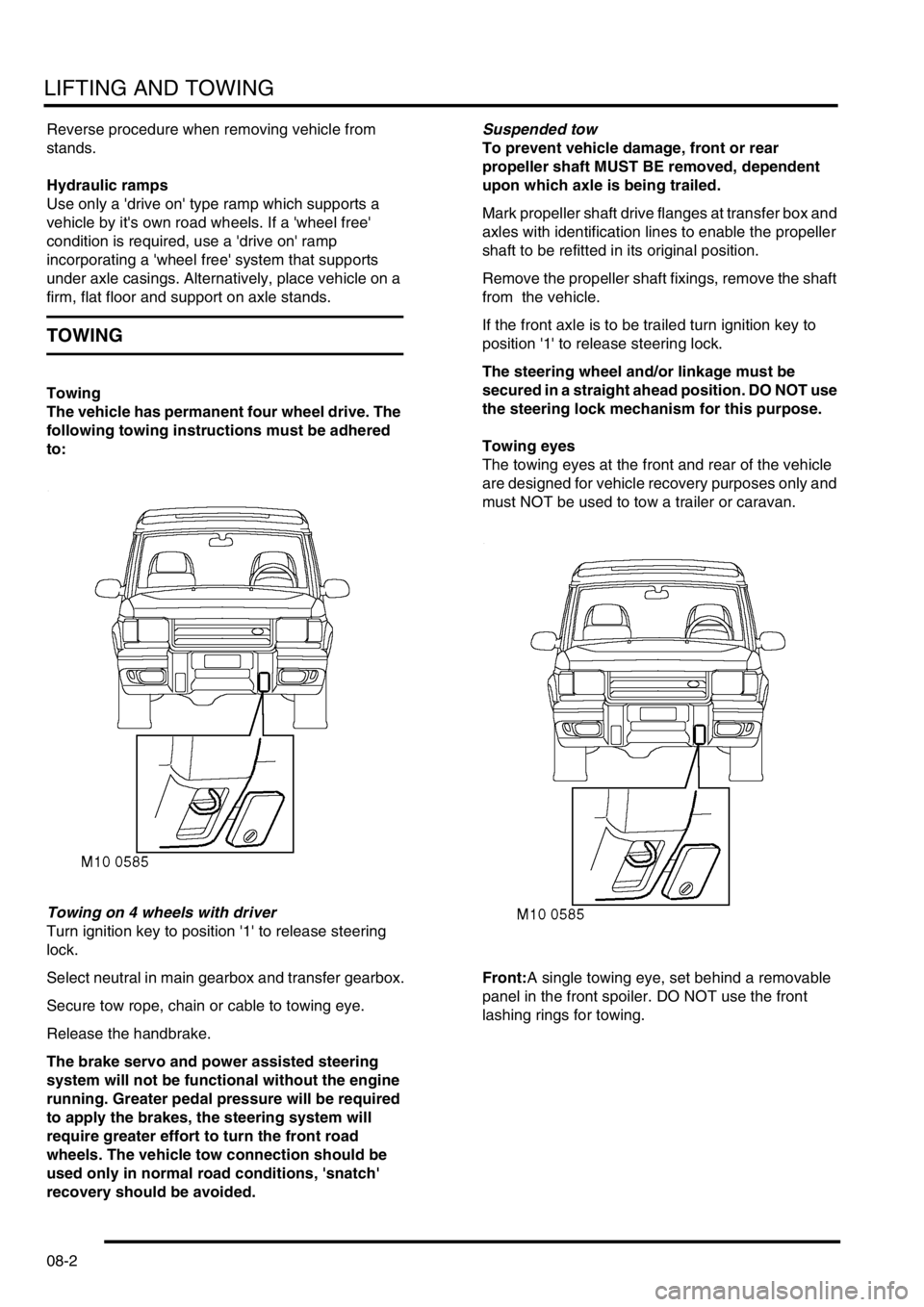
Towing eyes
The towing eyes at the front and rear of the vehicle
are designed for vehicle recovery purposes only and
must NOT be used to tow a trailer or caravan.
Front:A single towing eye, set behind a removable
panel in the front spoiler. DO NOT use the front
lashing rings for towing.
Page 114 of 1672
MAINTENANCE
PROCEDURES 10-5
Lamps, horns and warning indicators
Check
1.Switch on side, head and tail lamps and check
operation.
2.Check headlamp levelling operation.
3.Check turn signals and hazard warning lamps
for correct operation.
4.Press brake pedal and check operation of
brake lamps.
5.Check all exterior lamp lenses for clarity and
condition. Pay particular attention to headlamp
lenses for signs of stone chips or damage.
6.Check horn for loud, clear sound.
7.Switch on headlamps (with ignition switch at 'O'
position) and check light reminder warning
operates when door is opened.
8.Check operation of interior courtesy lights.
9.Check operation of all instrument pack warning
and indicator lights.
Wipers and washers
Check
1. Operate screen washer and switch on wipers.
Ensure washer jets are correctly aimed and
check for smooth, smear free operation of
wiper blades across screen at all speeds
including intermittent.
2.Repeat operation for rear screen washers/
wipers.
Page 137 of 1672

MAINTENANCE
10-28 PROCEDURES
4.Check condition of Engine - RH mounting
rubber
5.Check tightness of all mounting bolts.
+ TORQUE WRENCH SETTINGS,
Engine V8.
Road/roller test
WARNING: Roller test must be restricted to 3
mph (5 km/h). If 2 wheel rolling road is to be used,
disconnect propeller shaft from the transfer box
output shaft driving the axle which is NOT on the
rolling road.Testing
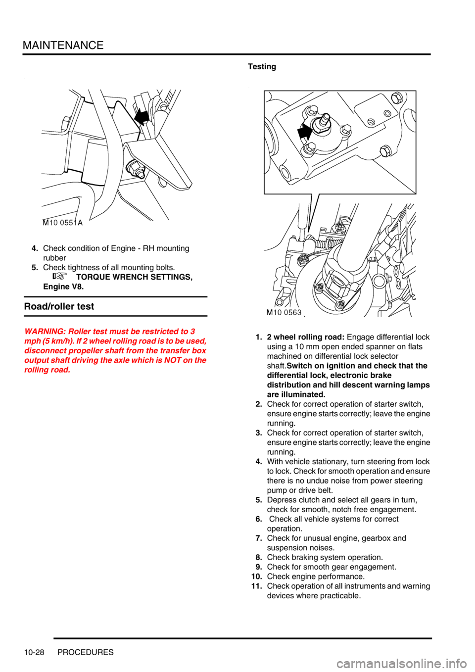
1. 2 wheel rolling road: Engage differential lock
using a 10 mm open ended spanner on flats
machined on differential lock selector
shaft.Switch on ignition and check that the
differential lock, electronic brake
distribution and hill descent warning lamps
are illuminated.
2.Check for correct operation of starter switch,
ensure engine starts correctly; leave the engine
running.
3.Check for correct operation of starter switch,
ensure engine starts correctly; leave the engine
running.
4.With vehicle stationary, turn steering from lock
to lock. Check for smooth operation and ensure
there is no undue noise from power steering
pump or drive belt.
5.Depress clutch and select all gears in turn,
check for smooth, notch free engagement.
6. Check all vehicle systems for correct
operation.
7.Check for unusual engine, gearbox and
suspension noises.
8.Check braking system operation.
9.Check for smooth gear engagement.
10.Check engine performance.
11.Check operation of all instruments and warning
devices where practicable.
Page 138 of 1672
MAINTENANCE
PROCEDURES 10-29
12.Where possible, check for correct operation of
hill descent control (HDC) mechanism. This
should not be carried out if excessive journey
time is required.
13.After road/roller test, carry out a final inspection
of vehicle, with vehicle on a ramp.
14.Check all fluid levels and top-up if necessary.
15. 2 wheel rolling road: Ensure differential lock is
disengaged and propeller shaft is connected on
completion of test. Switch on ignition and
check that differential lock, electronic brake
distribution and hill descent warning lamps
are extinguished.
Page 174 of 1672
ENGINE - TD5
ADJUSTMENTS 12-1-35
ADJUST ME NTS
Engine oil pressure check
$% 12.90.09.01
Check
1.Remove oil pressure switch.
+ ENGINE - Td5, REPAIRS, Switch -
oil pressure.
2.Connect pressure check kit LRT-12-052C
adaptor and gauge to oil pressure switch
position on oil cooler.
3.Check and if necessary top up engine oil.
4.Run engine at idle speed and check that oil
pressure is within limits given.
+ GENERAL DATA, Engine - Td5.
5.Switch off ignition.
6.Remove pressure check kit LRT-12-052C.
7.Clean oil spillage.
8.Fit oil pressure switch.
+ ENGINE - Td5, REPAIRS, Switch -
oil pressure.
Adjust
1.If engine oil pressure is outside of specified
limits, check condition of oil pump and/or main
and connecting rod bearings.
Page 252 of 1672

ENGINE - V8
DESCRIPTION AND OPERATION 12-2-9
element. Oil from the filter passes into the main oil gallery and through internal drillings to the crankshaft where it is
directed to each main bearing and to the big-end bearings via numbers 1, 3 and 5 main bearings. An internal drilling
in the cylinder block directs oil to the camshaft where it passes through further internal drillings to the hydraulic
tappets, camshaft bearing journals and rocker shafts. Lubrication to the pistons, small ends and cylinder bores is by
oil grooves machined in the connecting rods and by splash.
Oil pressure switch
The oil pressure warning light switch registers low oil pressure in the main oil gallery on the outflow side of the filter.
Whilst the engine is running and oil pressure is correct, the switch is open. When the ignition is switched on or if oil
pressure drops below the pressure setting of the switch, the switch closes and the low oil pressure warning lamp
located in the instrument pack will illuminate.
Hydraulic tappets
1Clip
2Pushrod seat
3Inner sleeve
4Upper chamber5Non-return ball valve
6Spring
7Outer sleeve
8Lower chamber
The hydraulic tappet provides maintenance free, quiet operation of the valves. This is achieved by utilizing engine oil
pressure to eliminate the clearance between the rocker arms and valve stems. When the valve is closed, engine oil
pressure present in the upper chamber, passes through the non-return ball valve and into the lower chamber. When
the cam begins to lift the outer sleeve, the resistance of the valve spring, felt through the push rod and seat, causes
the tappet inner sleeve to move downwards inside the outer sleeve. This downwards movement closes the non-return
ball valve and increases the pressure in the lower chamber sufficiently to ensure that the valve is fully opened by the
push rod. As the tappet moves off the peak of the cam, the non-return ball valve opens thereby allowing the pressure
in both chambers to equalize. This ensures that the valve will be fully closed when the tappet is on the back of the
cam.
Crankcase ventilation
A positive crankcase ventilation system is used to vent crankcase gases to the air induction system. Gases are drawn
from the left hand rocker cover to a tapping in the throttle body. An oil separator is incorporated in the hose connection
stub pipe in the right hand rocker cover, gases from this connection are drawn to a tapping in the inlet manifold.
+ EMISSION CONTROL - V8, DESCRIPTION AND OPERATION, Crankcase emission control system.
Page 254 of 1672
ENGINE - V8
ADJUSTMENTS 12-2-11
ADJUST ME NTS
Engine oil pressure check
$% 12.90.09.01
Check
1.Remove oil pressure switch.
+ ENGINE - V8, REPAIRS, Switch - oil
pressure.
2.Connect pressure check kit LRT-12-052C
adaptor and gauge to oil pressure switch
position on timing gear cover.
3.Check and if necessary top up engine oil.
4.Run engine at idle speed and check that oil
pressure is within limits given.
+ GENERAL DATA, Engine - V8.
5.Switch off ignition.
6.Remove pressure check kit LRT-12-052C.
7.Clean oil spillage.
8.Fit oil pressure switch.
+ ENGINE - V8, REPAIRS, Switch - oil
pressure.
Adjust
1.If engine oil pressure is below figures given,
check condition of oil pump and/or main and
big end bearings.
Page 269 of 1672
ENGINE - V8
12-2-26 REPAIRS
Engine assembly
$% 12.41.01.99
Remove
1.Drain engine oil and remove oil filter.
2.Remove radiator.
+ COOLING SYSTEM - V8, REPAIRS,
Radiator.
3.Remove upper inlet manifold.
+ MANIFOLDS AND EXHAUST
SYSTEMS - V8, REPAIRS, Gasket - inlet
manifold - upper - Without Secondary Air
Injection.
4.Remove ignition coil assemblies.
5.Position absorbent material to catch spillage
and disconnect fuel pipe from fuel rail.
CAUTION: Always fit plugs to open
connections to prevent contamination.
6.Release 2 hose clips and remove top hose.
7.Using a 15 mm spanner, release auxiliary drive
belt tension and remove drive belt. 8.Remove 3 bolts securing ACE pump, release
pump and tie aside.
9.Disconnect multiplug from A/C compressor.
10.Remove 4 bolts securing A/C compressor,
release compressor and tie aside.