Page 1394 of 1672

AIR CONDITIONING
DESCRIPTION AND OPERATION 82-21
Diagnostics
The ATC ECU performs a diagnostic check each time the ignition is switched on. To avoid nuisance fault indications
at low light levels, the sunlight sensor is omitted from the diagnostic check. If a fault is detected, the audible warning
sounds three times and the AUTO window on the control panel display flashes for 20 seconds. The ATC ECU then
reverts to normal control but uses a default value or strategy for the detected fault. Faults are identified by performing
a manual diagnostic check of the system.
A manual diagnostic check includes a check of the sunlight sensor, and is initiated by pressing and holding the AUTO
switch and the air distribution switch, then turning the ignition switch from off to on. The audible warning sounds once
and the indications on the control panel display illuminate. FC is shown in the LH temperature window and the results
of the check are shown as a two digit fault code in the RH temperature window. If a fault is detected, the audible
warning sounds three times and the AUTO window on the display flashes on and off for 20 seconds. If more than one
fault is detected, the fault codes cycle in numerical order, at 1 Hz. The audible warning sounds as each fault code is
shown. In low light conditions, to avoid false sunlight sensor fault indications, the sunlight sensor should be illuminated
with a strong light source.
Diagnostic fault codes and fault descriptions
Code Component Fault Default value/strategy
00 - No fault found -
11 In-car temperature sensor Open or short circuit 25°C (77°F)
12 Ambient temperature sensor Open or short circuit 10°C (50°F)
Cooling fan permanently on
Display shows "- -" if external
air temperature selected
13 Thermistor Open or short circuit 0°C (32°F)
14 Heater coolant temperature sensor Open or short circuit 70°C (158°F)
21 Sunlight sensor, left output Open or short circuit No solar heating correction
22 Sunlight sensor, right output Open or short circuit No solar heating correction
31 LH temperature servo motor Open or short circuit
Motor or flap mechanism seizedServo motor locked in position
32 RH temperature servo motor Open or short circuit
Motor or flap mechanism seizedServo motor locked in position
33 Distribution servo motor Open or short circuit
Motor or flap mechanism seizedServo motor locked in position
Page 1404 of 1672

AIR CONDITIONING
REPAIRS 82-31
REPAIRS
Compressor - diesel
$% 82.10.20
Remove
1.Remove engine acoustic cover.
2.Depressurise air conditioning system.
+ AIR CONDITIONING, REFRIGERANT
RECOVERY, RECYCLING AND
RECHARGING, Refrigerant recovery,
recycling and recharging.
3.Remove auxiliary drive belt.
+ CHARGING AND STARTING,
REPAIRS, Belt - auxiliary drive.
4.Drain cooling system.
+ COOLING SYSTEM - Td5,
ADJUSTMENTS, Drain and refill.
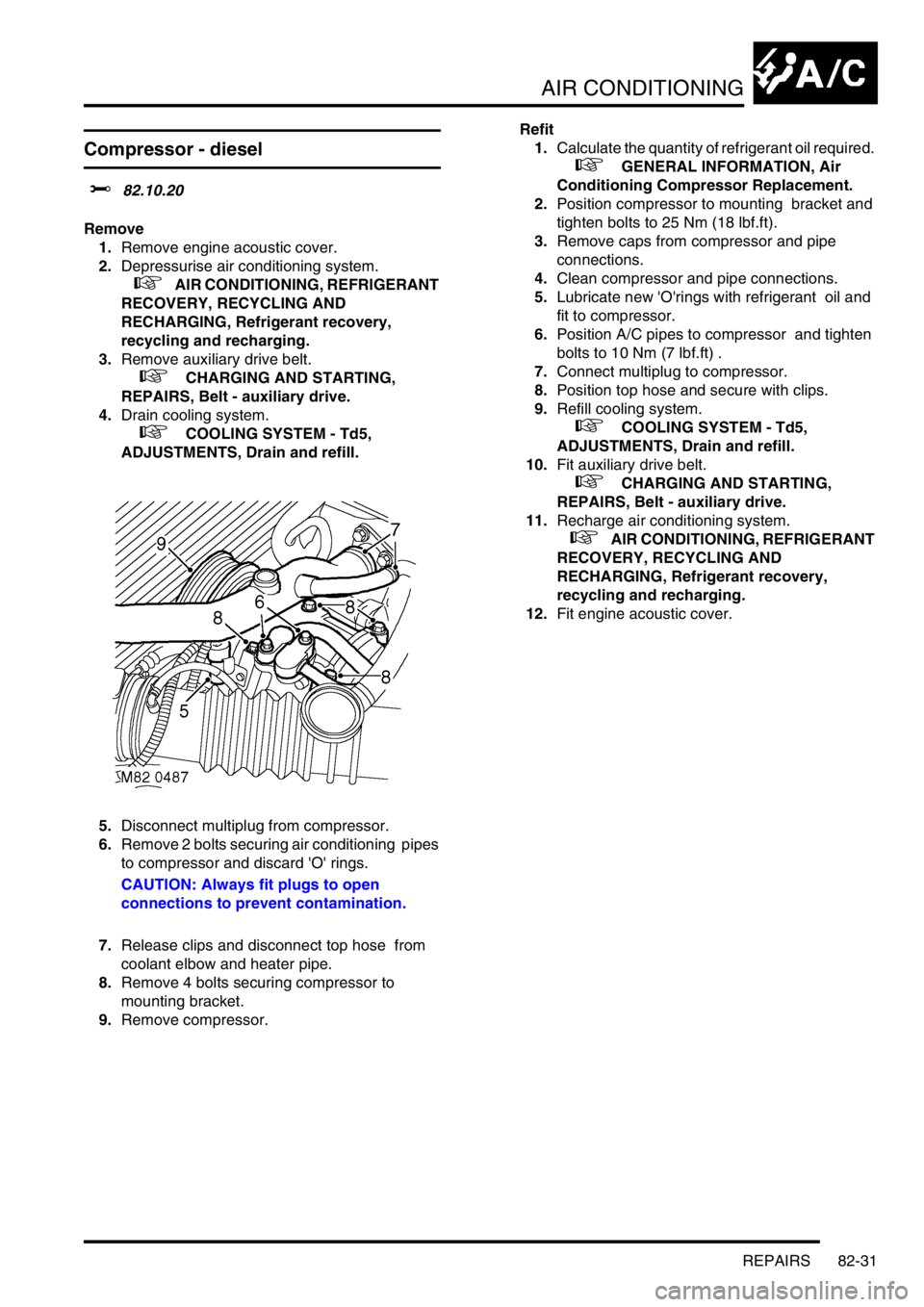
5.Disconnect multiplug from compressor.
6.Remove 2 bolts securing air conditioning pipes
to compressor and discard 'O' rings.
CAUTION: Always fit plugs to open
connections to prevent contamination.
7.Release clips and disconnect top hose from
coolant elbow and heater pipe.
8.Remove 4 bolts securing compressor to
mounting bracket.
9.Remove compressor.Refit
1.Calculate the quantity of refrigerant oil required.
+ GENERAL INFORMATION, Air
Conditioning Compressor Replacement.
2.Position compressor to mounting bracket and
tighten bolts to 25 Nm (18 lbf.ft).
3.Remove caps from compressor and pipe
connections.
4.Clean compressor and pipe connections.
5.Lubricate new 'O'rings with refrigerant oil and
fit to compressor.
6.Position A/C pipes to compressor and tighten
bolts to 10 Nm (7 lbf.ft) .
7.Connect multiplug to compressor.
8.Position top hose and secure with clips.
9.Refill cooling system.
+ COOLING SYSTEM - Td5,
ADJUSTMENTS, Drain and refill.
10.Fit auxiliary drive belt.
+ CHARGING AND STARTING,
REPAIRS, Belt - auxiliary drive.
11.Recharge air conditioning system.
+ AIR CONDITIONING, REFRIGERANT
RECOVERY, RECYCLING AND
RECHARGING, Refrigerant recovery,
recycling and recharging.
12.Fit engine acoustic cover.
Page 1406 of 1672

AIR CONDITIONING
REPAIRS 82-33
Fan - condenser
$% 82.15.01
Remove
1.Remove front grille.
+ EXTERIOR FITTINGS, REPAIRS,
Grille - front - up to 03MY.
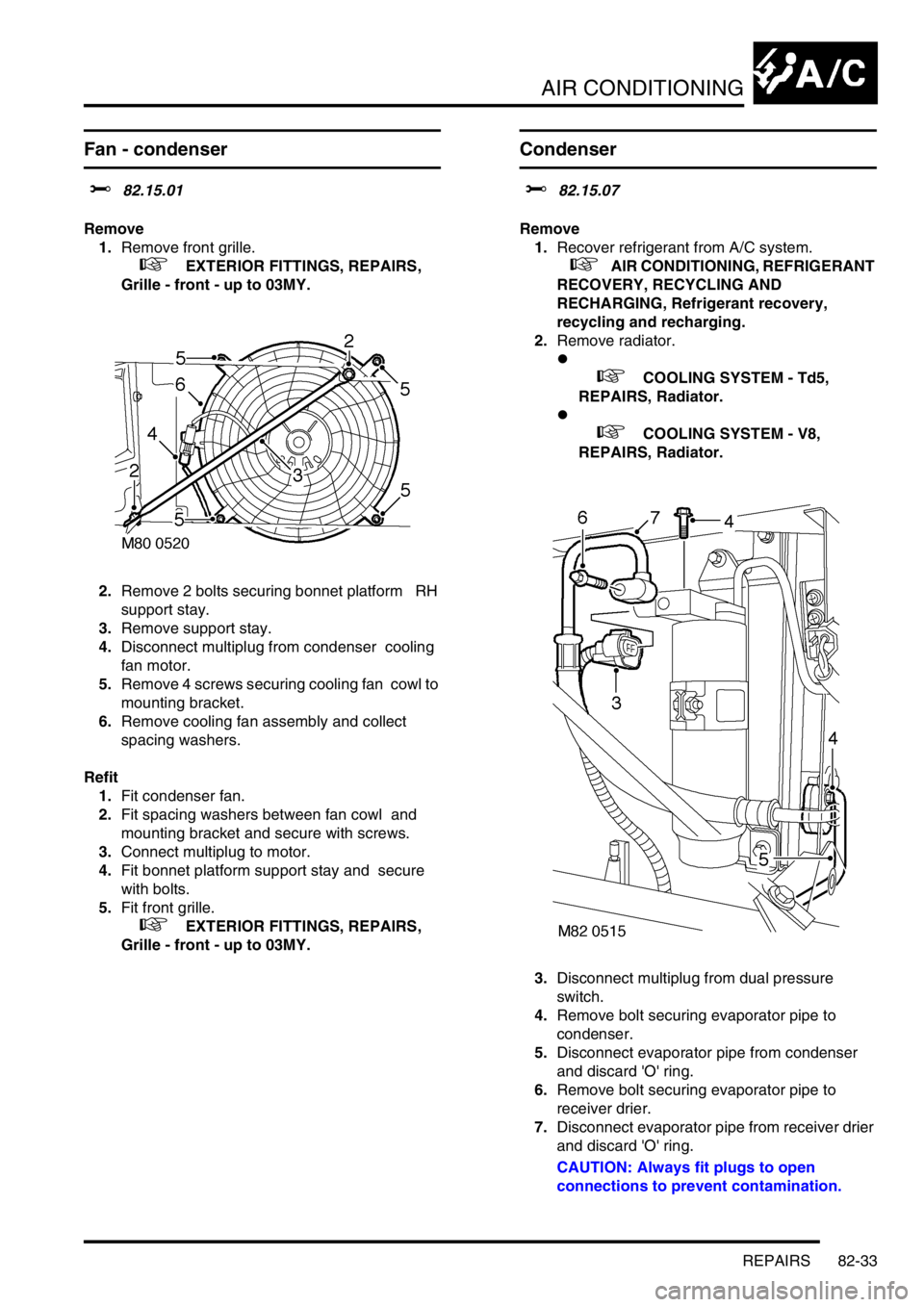
2.Remove 2 bolts securing bonnet platform RH
support stay.
3.Remove support stay.
4.Disconnect multiplug from condenser cooling
fan motor.
5.Remove 4 screws securing cooling fan cowl to
mounting bracket.
6.Remove cooling fan assembly and collect
spacing washers.
Refit
1.Fit condenser fan.
2.Fit spacing washers between fan cowl and
mounting bracket and secure with screws.
3.Connect multiplug to motor.
4.Fit bonnet platform support stay and secure
with bolts.
5.Fit front grille.
+ EXTERIOR FITTINGS, REPAIRS,
Grille - front - up to 03MY.
Condenser
$% 82.15.07
Remove
1.Recover refrigerant from A/C system.
+ AIR CONDITIONING, REFRIGERANT
RECOVERY, RECYCLING AND
RECHARGING, Refrigerant recovery,
recycling and recharging.
2.Remove radiator.
l
+ COOLING SYSTEM - Td5,
REPAIRS, Radiator.
l
+ COOLING SYSTEM - V8,
REPAIRS, Radiator.
3.Disconnect multiplug from dual pressure
switch.
4.Remove bolt securing evaporator pipe to
condenser.
5.Disconnect evaporator pipe from condenser
and discard 'O' ring.
6.Remove bolt securing evaporator pipe to
receiver drier.
7.Disconnect evaporator pipe from receiver drier
and discard 'O' ring.
CAUTION: Always fit plugs to open
connections to prevent contamination.
Page 1407 of 1672
AIR CONDITIONING
82-34REPAIRS
8.Remove 3 remaining bolts securing cooling fan
support rails to condenser.
9.Remove condenser.
10.Remove bolt securing adaptor block to receiver
drier.
11.Remove adaptor block from receiver drier and
discard 'O' ring.
CAUTION: Always fit plugs to open
connections to prevent contamination.12.Remove bolt securing condenser pipe to
receiver drier.
13.Remove clamp bolt receiver drier to bracket
and remove drier from bracket.
14.Remove and discard 'O' ring from condenser
pipe.
CAUTION: Always fit plugs to open
connections to prevent contamination.
15.Remove 2 remaining bolts securing receiver
drier brackets and condenser LH mounting
bracket to condenser.
16.Remove mounting bracket assembly.
17.Remove remaining bolt securing condenser RH
mounting and remove mounting.
Page 1408 of 1672

AIR CONDITIONING
REPAIRS 82-35
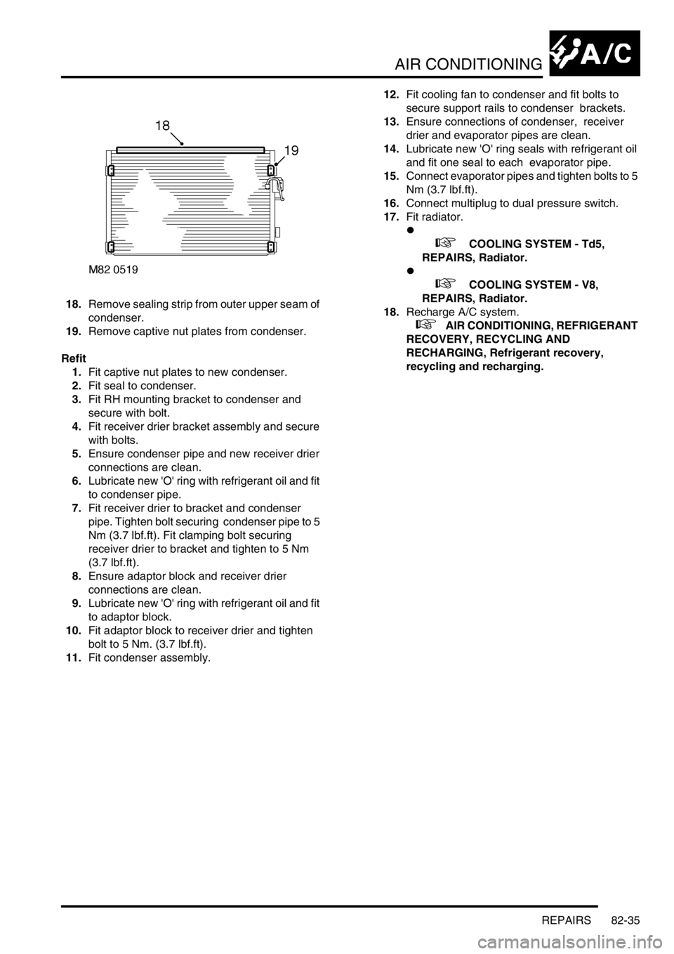
18.Remove sealing strip from outer upper seam of
condenser.
19.Remove captive nut plates from condenser.
Refit
1.Fit captive nut plates to new condenser.
2.Fit seal to condenser.
3.Fit RH mounting bracket to condenser and
secure with bolt.
4.Fit receiver drier bracket assembly and secure
with bolts.
5.Ensure condenser pipe and new receiver drier
connections are clean.
6.Lubricate new 'O' ring with refrigerant oil and fit
to condenser pipe.
7.Fit receiver drier to bracket and condenser
pipe. Tighten bolt securing condenser pipe to 5
Nm (3.7 lbf.ft). Fit clamping bolt securing
receiver drier to bracket and tighten to 5 Nm
(3.7 lbf.ft).
8.Ensure adaptor block and receiver drier
connections are clean.
9.Lubricate new 'O' ring with refrigerant oil and fit
to adaptor block.
10.Fit adaptor block to receiver drier and tighten
bolt to 5 Nm. (3.7 lbf.ft).
11.Fit condenser assembly. 12.Fit cooling fan to condenser and fit bolts to
secure support rails to condenser brackets.
13.Ensure connections of condenser, receiver
drier and evaporator pipes are clean.
14.Lubricate new 'O' ring seals with refrigerant oil
and fit one seal to each evaporator pipe.
15.Connect evaporator pipes and tighten bolts to 5
Nm (3.7 lbf.ft).
16.Connect multiplug to dual pressure switch.
17.Fit radiator.
l
+ COOLING SYSTEM - Td5,
REPAIRS, Radiator.
l
+ COOLING SYSTEM - V8,
REPAIRS, Radiator.
18.Recharge A/C system.
+ AIR CONDITIONING, REFRIGERANT
RECOVERY, RECYCLING AND
RECHARGING, Refrigerant recovery,
recycling and recharging.
Page 1450 of 1672
CHARGING AND STARTING
REPAIRS 86-1-1
CHARGING AND STARTING REPAIRS
Alternator - diesel
$% 86.10.02
Remove
1.Remove auxiliary drive belt.
+ CHARGING AND STARTING,
REPAIRS, Belt - auxiliary drive.
2.Release cover and remove nut securing lead
to alternator.
3.Disconnect alternator multiplug.
4.Remove bolt (LH thread) and remove auxiliary
drive belt tensioner. 5.Remove bolt securing support stay to
alternator.
6.Release clip and disconnect oil drain hose from
vacuum pump.
7.Disconnect vacuum pump oil supply pipe from
cylinder head and discard 'O' ring.
8.Remove bolt securing alternator and release
from mounting bracket.
9.Disconnect vacuum hose from vacuum pump.
10.Remove alternator. Take care not to damage
radiator cooling fins.
11.Remove 4 bolts, and remove vacuum pump
from alternator.
CAUTION: Always fit plugs to open
connections to prevent contamination.
Page 1452 of 1672

CHARGING AND STARTING
REPAIRS 86-1-3
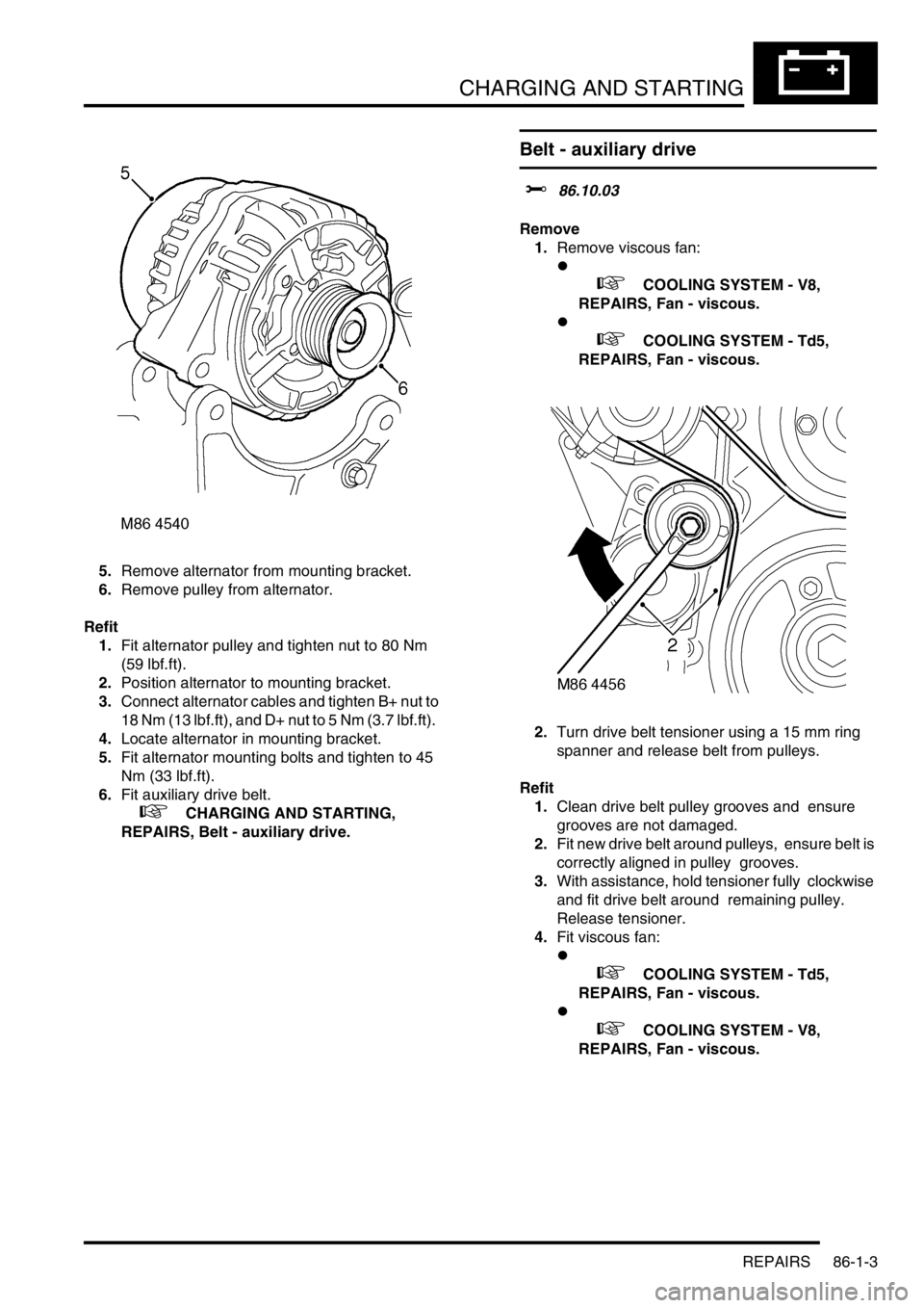
5.Remove alternator from mounting bracket.
6.Remove pulley from alternator.
Refit
1.Fit alternator pulley and tighten nut to 80 Nm
(59 lbf.ft).
2.Position alternator to mounting bracket.
3.Connect alternator cables and tighten B+ nut to
18 Nm (13 lbf.ft), and D+ nut to 5 Nm (3.7 lbf.ft).
4.Locate alternator in mounting bracket.
5.Fit alternator mounting bolts and tighten to 45
Nm (33 lbf.ft).
6.Fit auxiliary drive belt.
+ CHARGING AND STARTING,
REPAIRS, Belt - auxiliary drive.
Belt - auxiliary drive
$% 86.10.03
Remove
1.Remove viscous fan:
l
+ COOLING SYSTEM - V8,
REPAIRS, Fan - viscous.
l
+ COOLING SYSTEM - Td5,
REPAIRS, Fan - viscous.
2.Turn drive belt tensioner using a 15 mm ring
spanner and release belt from pulleys.
Refit
1.Clean drive belt pulley grooves and ensure
grooves are not damaged.
2.Fit new drive belt around pulleys, ensure belt is
correctly aligned in pulley grooves.
3.With assistance, hold tensioner fully clockwise
and fit drive belt around remaining pulley.
Release tensioner.
4.Fit viscous fan:
l
+ COOLING SYSTEM - Td5,
REPAIRS, Fan - viscous.
l
+ COOLING SYSTEM - V8,
REPAIRS, Fan - viscous.
Page 1588 of 1672
HARNESSES
REPAIRS 86-7-17
9.Disconnect multiplugs from cooling fan and
horn.
10.Release 3 cable tie clips from front RH panel.
11.Remove RH indicator lamp.
+ LIGHTING, REPAIRS, Lamp - front
repeater.12.Disconnect multiplugs from headlamp and
sidelamp.
13.Disconnect multiplug from headlamp levelling
motor.