2002 LAND ROVER DISCOVERY relay
[x] Cancel search: relayPage 1543 of 1672
WINDOWS
86-5-4 DESCRIPTION AND OPERATION
Description
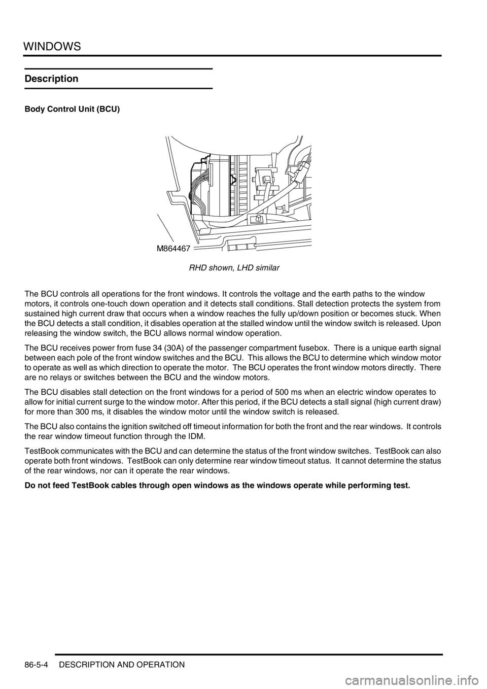
Body Control Unit (BCU)
RHD shown, LHD similar
The BCU controls all operations for the front windows. It controls the voltage and the earth paths to the window
motors, it controls one-touch down operation and it detects stall conditions. Stall detection protects the system from
sustained high current draw that occurs when a window reaches the fully up/down position or becomes stuck. When
the BCU detects a stall condition, it disables operation at the stalled window until the window switch is released. Upon
releasing the window switch, the BCU allows normal window operation.
The BCU receives power from fuse 34 (30A) of the passenger compartment fusebox. There is a unique earth signal
between each pole of the front window switches and the BCU. This allows the BCU to determine which window motor
to operate as well as which direction to operate the motor. The BCU operates the front window motors directly. There
are no relays or switches between the BCU and the window motors.
The BCU disables stall detection on the front windows for a period of 500 ms when an electric window operates to
allow for initial current surge to the window motor. After this period, if the BCU detects a stall signal (high current draw)
for more than 300 ms, it disables the window motor until the window switch is released.
The BCU also contains the ignition switched off timeout information for both the front and the rear windows. It controls
the rear window timeout function through the IDM.
TestBook communicates with the BCU and can determine the status of the front window switches. TestBook can also
operate both front windows. TestBook can only determine rear window timeout status. It cannot determine the status
of the rear windows, nor can it operate the rear windows.
Do not feed TestBook cables through open windows as the windows operate while performing test.
Page 1546 of 1672
WINDOWS
DESCRIPTION AND OPERATION 86-5-7
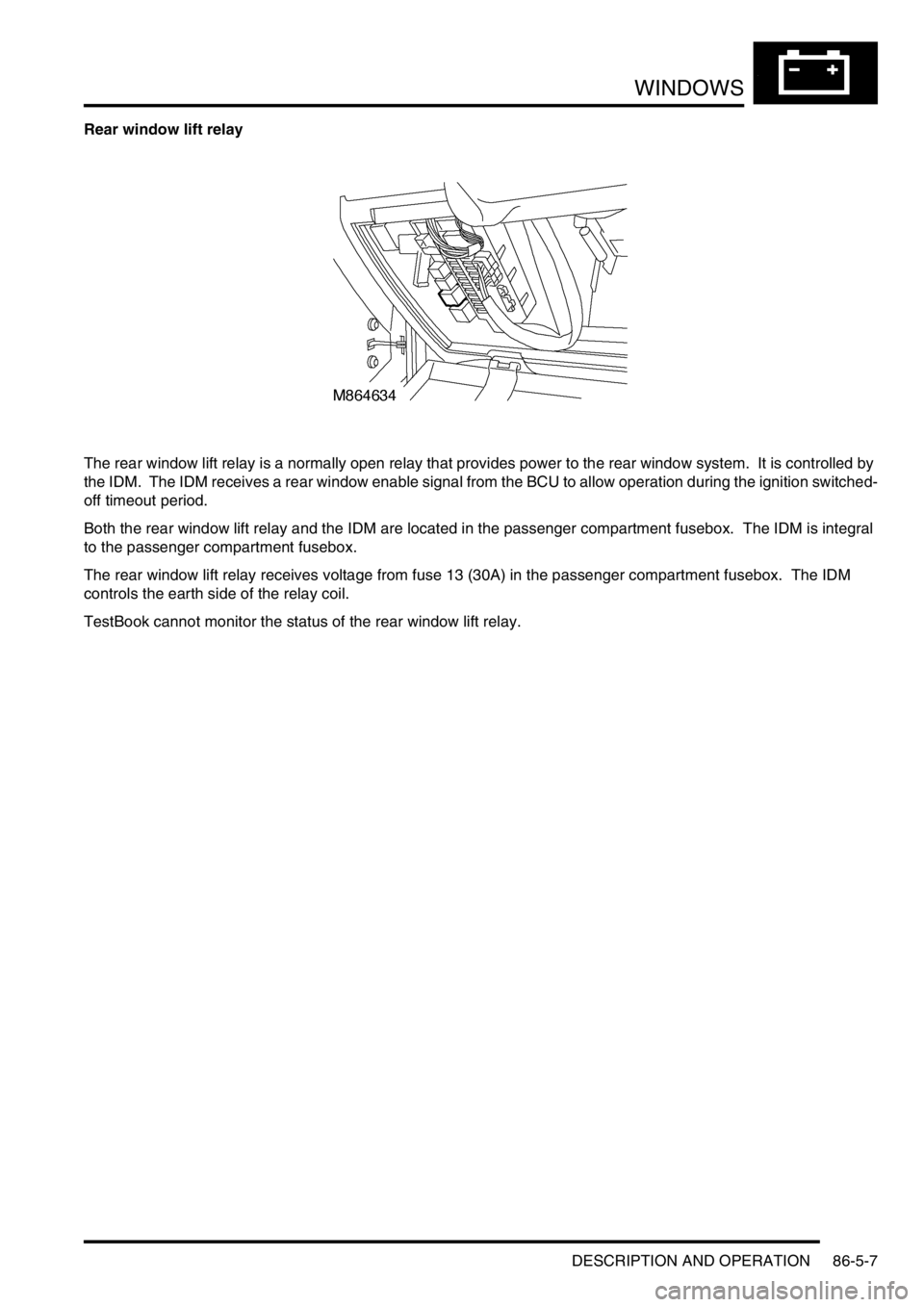
Rear window lift relay
The rear window lift relay is a normally open relay that provides power to the rear window system. It is controlled by
the IDM. The IDM receives a rear window enable signal from the BCU to allow operation during the ignition switched-
off timeout period.
Both the rear window lift relay and the IDM are located in the passenger compartment fusebox. The IDM is integral
to the passenger compartment fusebox.
The rear window lift relay receives voltage from fuse 13 (30A) in the passenger compartment fusebox. The IDM
controls the earth side of the relay coil.
TestBook cannot monitor the status of the rear window lift relay.
Page 1547 of 1672

WINDOWS
86-5-8 DESCRIPTION AND OPERATION
Rear window switches
There are two sets of switches that operate the rear windows. There is a set of rear window switches located in the
centre console that allow the front seat occupants to operate the rear windows. The second set of switches are
located on the rear doors. All rear window switches are non-latching rocker switches.
A conventional window switch circuit controls the rear window system. In the rest position, there is battery voltage at
both sides of every switch as well as at the window motors. Operating any switch provides a ground path through the
switch to the window motor. Operating the switch in the opposite direction switches the voltage path and the earth
path to the motor allowing the motor to run in the opposite direction.
Voltage for the rear windows is from fuse 13 (30A) in the passenger compartment fusebox through the rear window
lift relay to the switches and motors.
TestBook cannot monitor the status of the rear window switches.
Page 1555 of 1672
IN CAR ENTERTAINMENT
86-6-2 DESCRIPTION AND OPERATION
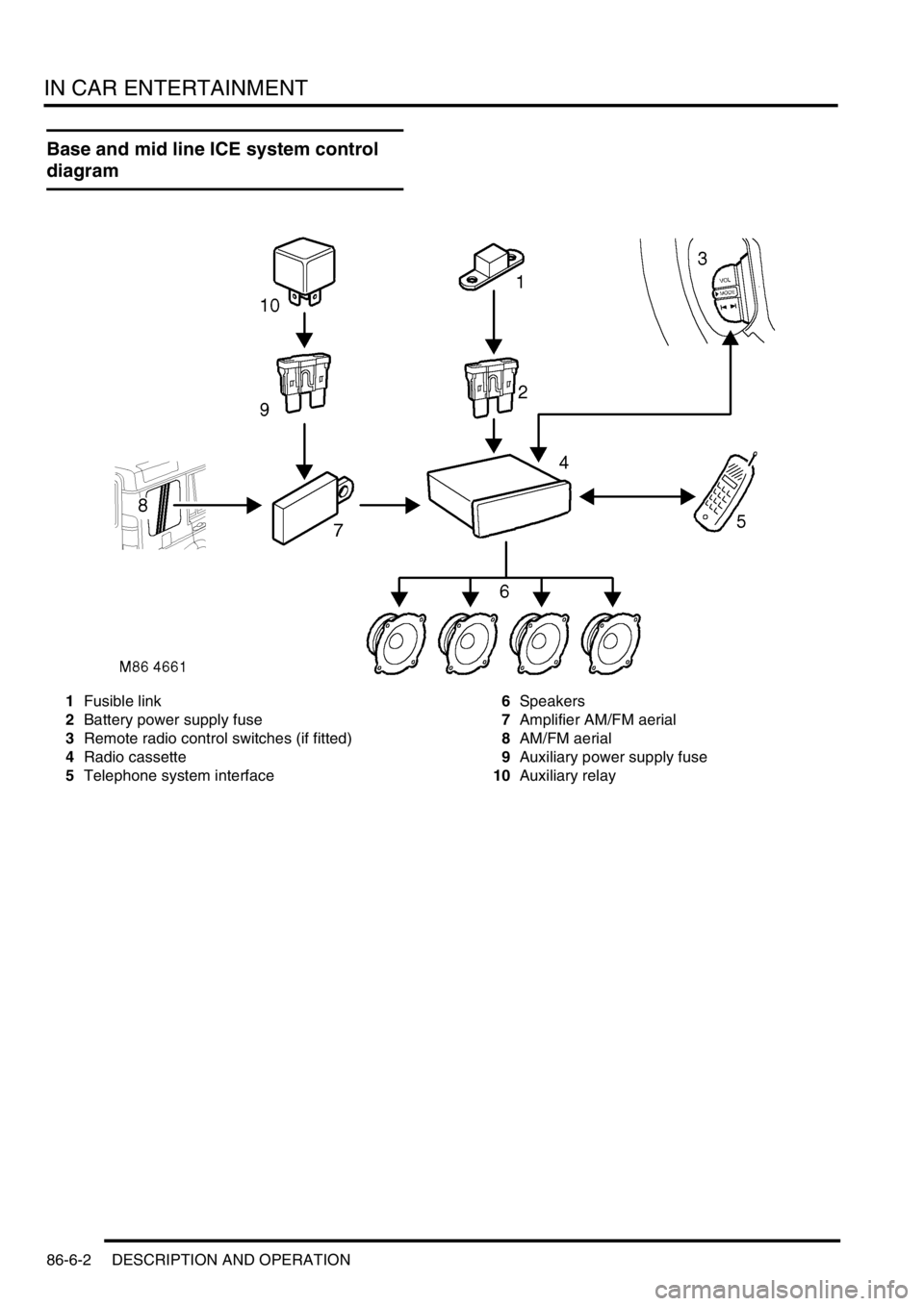
Base and mid line ICE system control
diagram
1Fusible link
2Battery power supply fuse
3Remote radio control switches (if fitted)
4Radio cassette
5Telephone system interface6Speakers
7Amplifier AM/FM aerial
8AM/FM aerial
9Auxiliary power supply fuse
10Auxiliary relay
Page 1556 of 1672
IN CAR ENTERTAINMENT
DESCRIPTION AND OPERATION 86-6-3
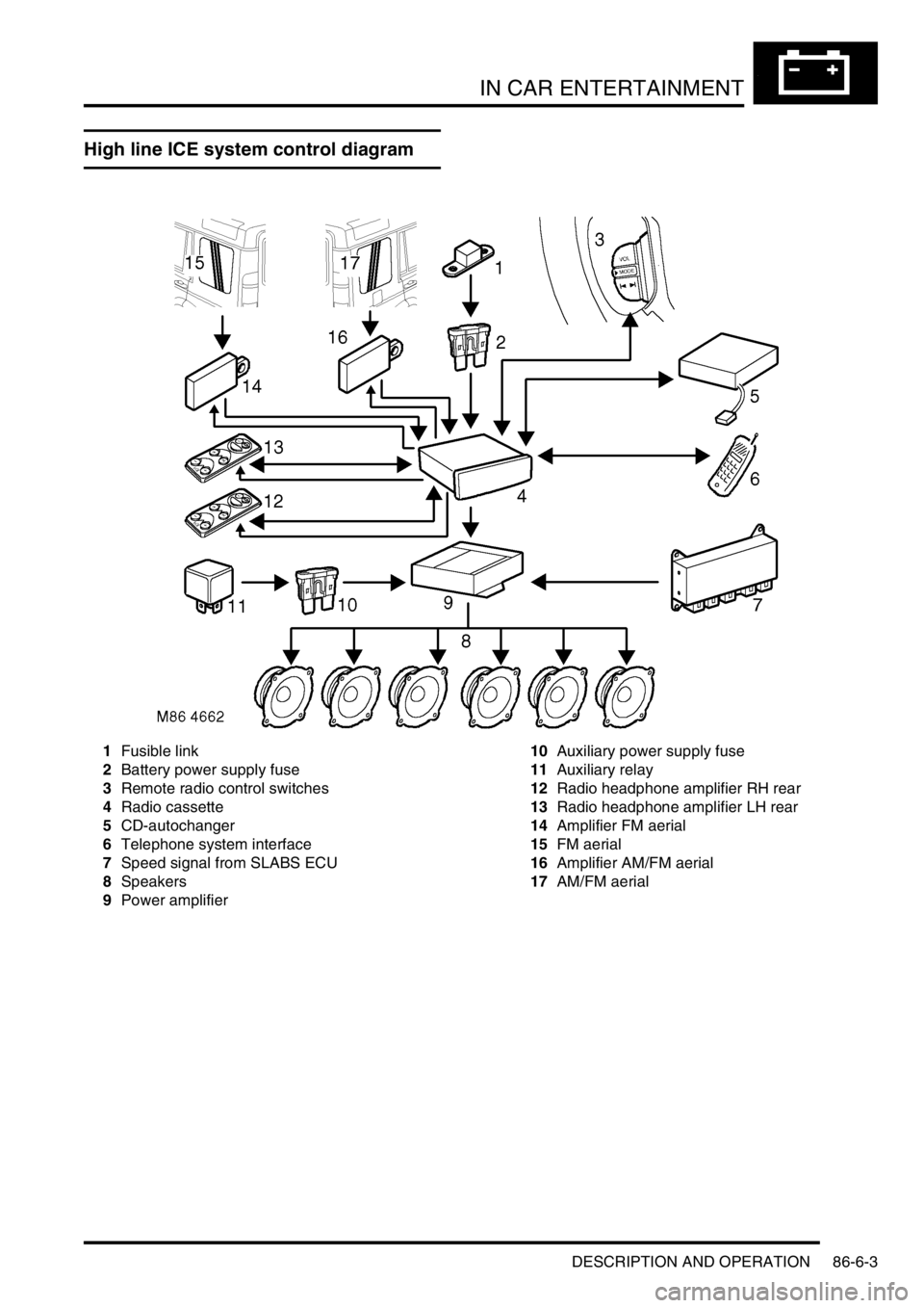
High line ICE system control diagram
1Fusible link
2Battery power supply fuse
3Remote radio control switches
4Radio cassette
5CD-autochanger
6Telephone system interface
7Speed signal from SLABS ECU
8Speakers
9Power amplifier10Auxiliary power supply fuse
11Auxiliary relay
12Radio headphone amplifier RH rear
13Radio headphone amplifier LH rear
14Amplifier FM aerial
15FM aerial
16Amplifier AM/FM aerial
17AM/FM aerial
Page 1563 of 1672

IN CAR ENTERTAINMENT
86-6-10 DESCRIPTION AND OPERATION
Remote radio steering wheel controls (midline and high line systems)
The remote radio control switch is located on the LH side of the steering wheel and is secured with two screws. The
wiring from the remote radio control switch plugs in to a connector that is part of the steering wheel rotary coupler.
Operation of the remote radio control switches allow the driver to control the ICE without releasing the steering wheel.
Volume, mode and selection functions can be carried out using the steering wheel mounted control switches. Control
inputs from the remote radio control switches are sent to the radio cassette player.
Aerial
On base and midline ICE systems an AM/FM aerial is built-in to the side window glass on the RH side of the vehicle.
An amplifier is located on the frame above the rear side widow behind the rear quarter trim, and is secured (and
earthed) with one bolt. Coaxial leads connect the aerial to the aerial amplifier and radio cassette. Power is supplied
from the auxilary relay in the engine compartment fuse box, through a fuse in the passenger compartment fusebox to
the amplifier.
On high line ICE systems two amplified aerials are built-in to the side window glass of the vehicle. The two aerials are
an AM/FM aerial on the RH side, and an FM aerial on the LH side. The amplifier for each aerial are located on the
frame above each rear side widow behind the rear quarter trim, and are each secured (and earthed) with one bolt.
Amplified aerials improve the reception quality, the FM aerial gives improved reception in areas of poor signal
(diversity) conditions in urban areas. A Power feed from the radio cassette player is connected to the amplified aerials,
power is available when the cassette player is operating. The aerials are connected to the radio cassette player by
two coaxial cables, a small plug connects the FM only aerial, a larger plug connects the AM/FM aerial.
Power amplifier (high line system)
The amplifier is located on a bracket under the LH front seat and is secured with three screws and washers. The
amplifier receives inputs from the radio, radio cassette player or (via the radio cassette player) the CD-autochanger.
Power for the amplifier is supplied from the passenger compartment fuse box. The amplifier will power up when an
enable logic signal is sent from the radio cassette, this signal is sent by the radio cassette when it is turned on.
CD-autochanger (high line system)
A CD-autochanger is located under the RH front seat, the unit is secured to brackets in the floor with four screws and
washers. A tray is used to hold each compact disk (CD), the loaded tray is then inserted in a magazine, the magazine
holds six trays and is then inserted into the CD-autochanger. A sliding cover protects the internal components of the
CD-autochanger from dirt entry through the magazine opening. An eject button located on the front of the CD-
autochanger can be used to release the magazine from the CD-autochanger. The sliding cover has to be opened
manually before the magazine eject button is pressed. The operation of the CD-autochanger is controlled by inputs
from the radio cassette, the control inputs can be from the radio cassette buttons, the remote radio controls or the rear
radio headphone amplifiers if they are fitted. The output from the CD-autochanger are connected to the radio cassette
player. The radio cassette player sends the outputs to the power amplifier. Power is supplied to the CD-autochanger
by a feed from the radio cassette player.
Radio headphone amplifiers (high line system)
The rear mounted radio headphone amplifiers are located in the lower rear quarter trim casing and are held in position
by a clip on the side of the headphone amplifier. Mode and function buttons are located on a control panel, the mode
button allows each of the rear seat passengers to independently select from the radio, tape or CD-autochanger. The
driver and the rear seat passengers can each listen to any of the audio devices they select. However the radio
cassette setting has overall priority e.g:
lIf the radio cassette is using a radio wave band (AM or FM), the headphone user will be able to select the cassette
tracks or CD-autochanger. The user will be able to listen to same radio band that is selected on the radio
cassette, but will not be able to change the station selected.
lIf the radio cassette has CD-autochanger selected, the headphone amplifiers will allow listening to the compact
disk but will not allow track changes. The headphone user will be able to select on all of the radio bands or
cassette tracks.
lIf the radio cassette has tape selected, the headphone amplifiers will allow listening to the tape but will not allow
track changes. The headphone user will be able to select all radio bands or CD's on the CD-autochanger.
Page 1657 of 1672
INSTRUMENTS
88-30 DESCRIPTION AND OPERATION
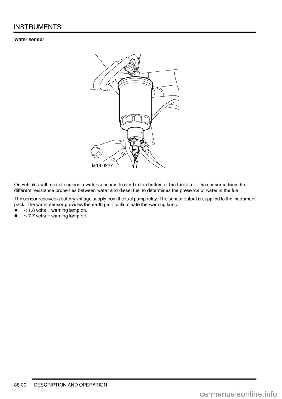
Water sensor
On vehicles with diesel engines a water sensor is located in the bottom of the fuel filter. The sensor utilises the
different resistance properties between water and diesel fuel to determines the presence of water in the fuel.
The sensor receives a battery voltage supply from the fuel pump relay. The sensor output is supplied to the instrument
pack. The water sensor provides the earth path to illuminate the warning lamp.
l< 1.8 volts = warning lamp on.
l> 7.7 volts = warning lamp off.
Page 1669 of 1672

INSTRUMENTS
88-42 DESCRIPTION AND OPERATION
Interior rear view mirror with compass
(where fitted)
1Cover
2Electrical connector
3Mounting bracket
4Light sensor
5Compass LED display
6Compass calibration switch
7Compass printed circuit board
Certain vehicles have an interior rear view mirror that features an automatic photochromatic dimming function and an
electronic compass with LED display.
The compass mirror is a self-contained unit and does not interface with any other vehicle system or electronic control
unit. The mirror is fixed to a metal bracket attached to the windscreen.
A three pin connector provides the electrical connection to the mirror's internal circuit board. Pin-1 of the connector
provides the 12V power supply to the board via the auxiliary relay located in the engine compartment fusebox. When
the ignition switch is turned to the 'II' position, a 12V supply is provided to energise the coil of the auxiliary relay via
fuse 26 in the passenger compartment fusebox. The auxiliary relay's contact supply voltage is provided from the
vehicle battery through fusible links 1 & 7. When the relay's contacts close, a 12V supply is fed to the compass mirror
circuit board via fuse 15 in the passenger compartment fusebox. This is the supply voltage feed for the mirror's internal
compass.
Pin-2 of the electrical connector provides the path to earth.
Pin-3 of the electrical connector is a 12V ignition switched supply voltage (position 'II' of the ignition switch). The
supply voltage is provided to the mirror's circuit board via fuse 25 in the passenger compartment fusebox, and the
reverse lamp switch (normally closed) for vehicles with manual transmission or the starter inhibitor / reverse light
switch (normally closed) for vehicles with automatic transmission. This is the supply voltage feed for the mirror's
photochromatic dimming function.
M88 0297
3
2
7
616
45