Page 1595 of 1672
HARNESSES
86-7-24 REPAIRS
70.Release fusebox and disconnect 8 multiplugs.
71.Remove fusebox.
72.Disconnect 7 multiplugs from ignition passive
coil and steering column switch assembly.
Page 1599 of 1672

HARNESSES
86-7-28 REPAIRS
18.Secure multiplugs to steering column support
bracket and connect brake and clutch pedal
multiplugs.
19.Connect multiplugs to column switch and
passive coil.
20.Position passenger compartment fusebox,
connect multiplugs, fit fusebox to fascia and
secure with nut.
21.Connect ignition switch multiplug to fuse box.
22.With assistance feed LH side of harness into
engine bay.
23.Connect multiplugs to front door harness and
body harness.
24.Position earth headers to LH lower 'A' post and
secure with nuts.
25.Connect multiplugs to ECU pack.
26.Position harness in engine bay.
27.Connect and secure heated front screen
multiplugs.
28.Fit plenum molding.
+ HEATING AND VENTILATION,
REPAIRS, Plenum Air Intake.
29.Connect multiplugs to ABS sensor and fuel
cut-off switch.
30.Using draw string feed harness through inner
wing, remove draw string, connect repeater
lamp multiplug and fit lamp.
31.Connect multiplugs to ABS modulator.
32.Feed harness through to front panel.
33.Position body earth leads and secure with
bolts.
34.Connect washer reservoir multiplugs and
pipes, secure pipes with clips.
35.Secure fog lamp multiplug.
36.Secure earth header behind headlamp.
37.Connect multiplugs to headlamp level motor,
headlamp and side lamp.
38.Fit indicator lamp
+ LIGHTING, REPAIRS, Lamp - front
repeater.
39.Connect multiplug to LH horn.
40.Feed harness to ACE accelerometer, connect
multiplug and secure with cable ties.
41.Connect cruise control, ABS sensor and brake
fluid level switch multiplugs.
42.Connect engine harness multiplug and feed
harness along RH wing to fuse box.
43.Using draw string pull harness through inner
wing, remove draw string, connect repeater
lamp multiplug and fit lamp. 44.Connect chassis harness multiplugs.
45.Position engine bay fuse box and connect
multiplugs, fit fuse box and secure with screws.
46.Connect multiplugs to front of fuse box.
47.Position battery and starter cables and secure
with screws.
48.Fit fuse box cover.
49.Position earth lead and secure with nut.
50.Feed harness through to front panel.
51.Secure fog lamp multiplug.
52.Connect headlamp level motor, headlamp and
side lamp multiplugs.
53.Fit indicator lamp.
+ LIGHTING, REPAIRS, Lamp - front
repeater.
54.Secure harness to RH front panel.
55.Connect cooling fan and horn multiplug.
56.Secure harness to lower support rail.
57.Connect receiver drier and air temperature
sensor multiplugs.
58.Fit front bumper.
+ EXTERIOR FITTINGS, REPAIRS,
Bumper assembly - front.
59.Fit battery tray.
60.Fit air filter assembly.
+ ENGINE MANAGEMENT SYSTEM -
V8, REPAIRS, Air cleaner assembly.
61.Position both lower 'A' post trims and secure
with studs.
62.Fit heater assembly.
+ HEATING AND VENTILATION,
REPAIRS, Heater assembly - models with
air conditioning.
+ HEATING AND VENTILATION,
REPAIRS, Heater assembly - models
without air conditioning.
Page 1602 of 1672
DRIVING AIDS
DESCRIPTION AND OPERATION 86-8-3
1PDC sounder
2PDC switch
3Fusible link
4Ignition switch
5Fuse
6PDC ECU
7PDC sensors
Page 1619 of 1672

NAVIGATION SYSTEM
87-4 DESCRIPTION AND OPERATION
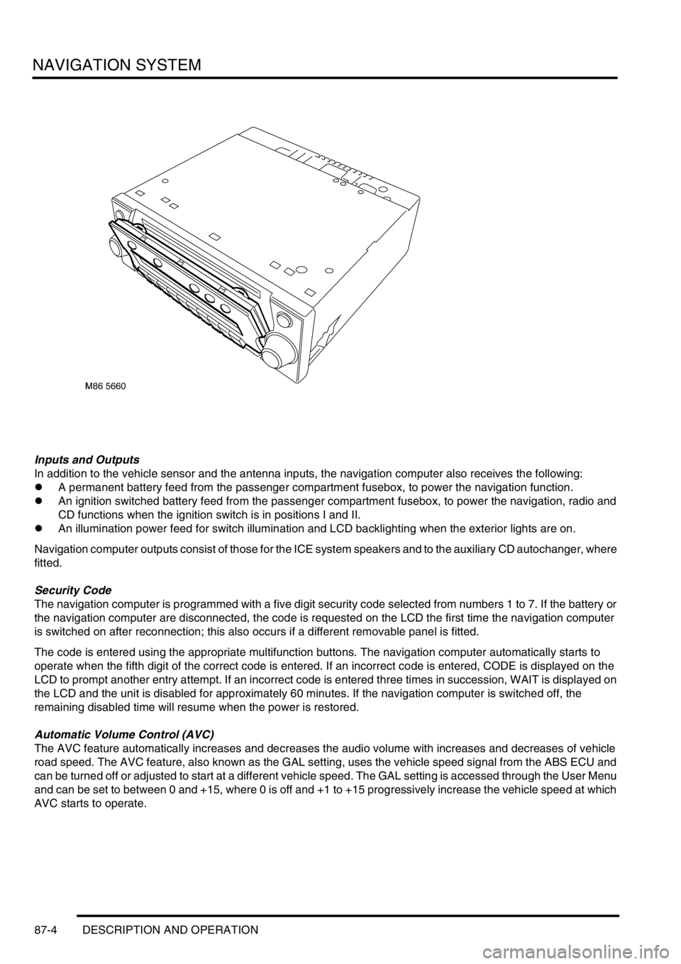
Inputs and Outputs
In addition to the vehicle sensor and the antenna inputs, the navigation computer also receives the following:
lA permanent battery feed from the passenger compartment fusebox, to power the navigation function.
lAn ignition switched battery feed from the passenger compartment fusebox, to power the navigation, radio and
CD functions when the ignition switch is in positions I and II.
lAn illumination power feed for switch illumination and LCD backlighting when the exterior lights are on.
Navigation computer outputs consist of those for the ICE system speakers and to the auxiliary CD autochanger, where
fitted.
Security Code
The navigation computer is programmed with a five digit security code selected from numbers 1 to 7. If the battery or
the navigation computer are disconnected, the code is requested on the LCD the first time the navigation computer
is switched on after reconnection; this also occurs if a different removable panel is fitted.
The code is entered using the appropriate multifunction buttons. The navigation computer automatically starts to
operate when the fifth digit of the correct code is entered. If an incorrect code is entered, CODE is displayed on the
LCD to prompt another entry attempt. If an incorrect code is entered three times in succession, WAIT is displayed on
the LCD and the unit is disabled for approximately 60 minutes. If the navigation computer is switched off, the
remaining disabled time will resume when the power is restored.
Automatic Volume Control (AVC)
The AVC feature automatically increases and decreases the audio volume with increases and decreases of vehicle
road speed. The AVC feature, also known as the GAL setting, uses the vehicle speed signal from the ABS ECU and
can be turned off or adjusted to start at a different vehicle speed. The GAL setting is accessed through the User Menu
and can be set to between 0 and +15, where 0 is off and +1 to +15 progressively increase the vehicle speed at which
AVC starts to operate.
Page 1636 of 1672

INSTRUMENTS
DESCRIPTION AND OPERATION 88-9
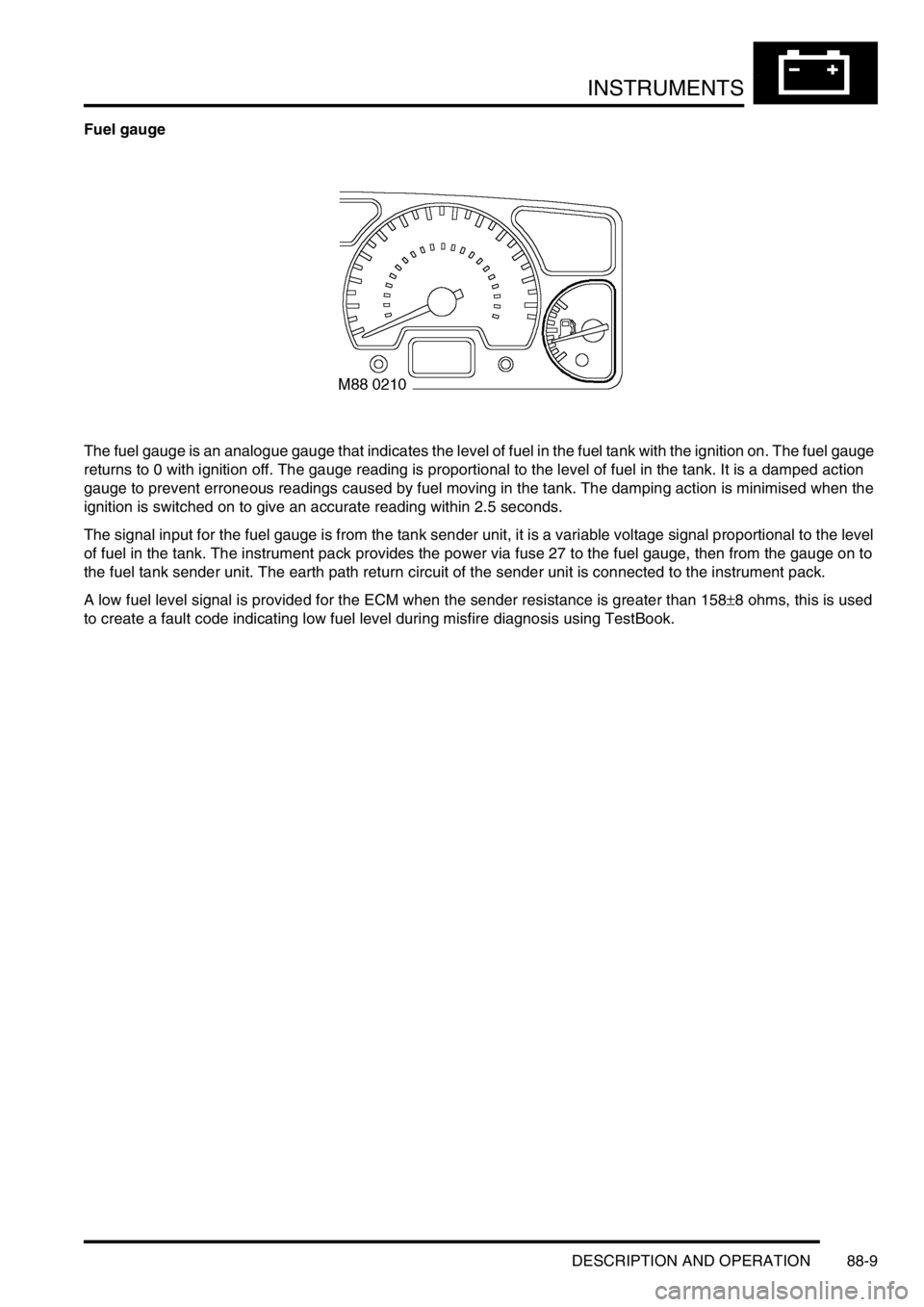
Fuel gauge
The fuel gauge is an analogue gauge that indicates the level of fuel in the fuel tank with the ignition on. The fuel gauge
returns to 0 with ignition off. The gauge reading is proportional to the level of fuel in the tank. It is a damped action
gauge to prevent erroneous readings caused by fuel moving in the tank. The damping action is minimised when the
ignition is switched on to give an accurate reading within 2.5 seconds.
The signal input for the fuel gauge is from the tank sender unit, it is a variable voltage signal proportional to the level
of fuel in the tank. The instrument pack provides the power via fuse 27 to the fuel gauge, then from the gauge on to
the fuel tank sender unit. The earth path return circuit of the sender unit is connected to the instrument pack.
A low fuel level signal is provided for the ECM when the sender resistance is greater than 158
±8 ohms, this is used
to create a fault code indicating low fuel level during misfire diagnosis using TestBook.
Page 1638 of 1672

INSTRUMENTS
DESCRIPTION AND OPERATION 88-11
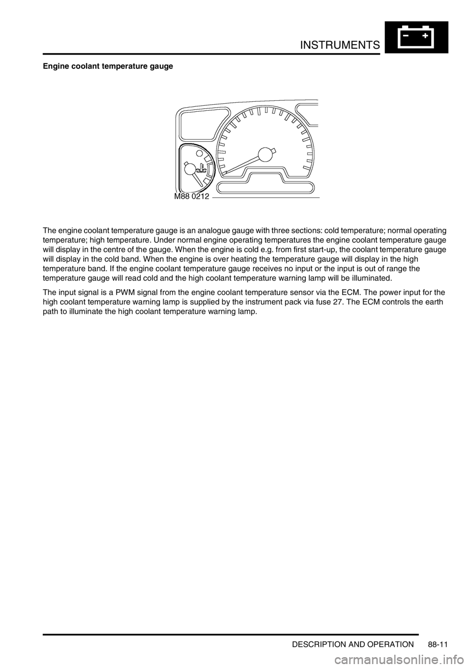
Engine coolant temperature gauge
The engine coolant temperature gauge is an analogue gauge with three sections: cold temperature; normal operating
temperature; high temperature. Under normal engine operating temperatures the engine coolant temperature gauge
will display in the centre of the gauge. When the engine is cold e.g. from first start-up, the coolant temperature gauge
will display in the cold band. When the engine is over heating the temperature gauge will display in the high
temperature band. If the engine coolant temperature gauge receives no input or the input is out of range the
temperature gauge will read cold and the high coolant temperature warning lamp will be illuminated.
The input signal is a PWM signal from the engine coolant temperature sensor via the ECM. The power input for the
high coolant temperature warning lamp is supplied by the instrument pack via fuse 27. The ECM controls the earth
path to illuminate the high coolant temperature warning lamp.
Page 1639 of 1672

INSTRUMENTS
88-12 DESCRIPTION AND OPERATION
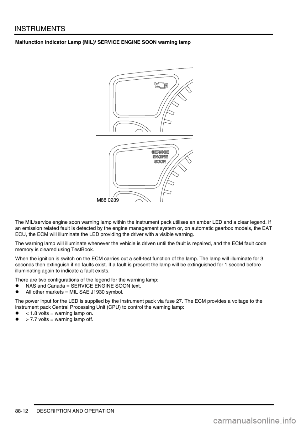
Malfunction Indicator Lamp (MIL)/ SERVICE ENGINE SOON warning lamp
The MIL/service engine soon warning lamp within the instrument pack utilises an amber LED and a clear legend. If
an emission related fault is detected by the engine management system or, on automatic gearbox models, the EAT
ECU, the ECM will illuminate the LED providing the driver with a visible warning.
The warning lamp will illuminate whenever the vehicle is driven until the fault is repaired, and the ECM fault code
memory is cleared using TestBook.
When the ignition is switch on the ECM carries out a self-test function of the lamp. The lamp will illuminate for 3
seconds then extinguish if no faults exist. If a fault is present the lamp will be extinguished for 1 second before
illuminating again to indicate a fault exists.
There are two configurations of the legend for the warning lamp:
lNAS and Canada = SERVICE ENGINE SOON text.
lAll other markets = MIL SAE J1930 symbol.
The power input for the LED is supplied by the instrument pack via fuse 27. The ECM provides a voltage to the
instrument pack Central Processing Unit (CPU) to control the warning lamp:
l< 1.8 volts = warning lamp on.
l> 7.7 volts = warning lamp off.
Page 1643 of 1672
INSTRUMENTS
88-16 DESCRIPTION AND OPERATION
Direction indicator warning lamps
The direction indicator warning lamp within the instrument pack utilises a green LED and a clear legend. The LED
flashes at the same rate as the external indicators, providing the driver with a visible warning.
Operating the left-hand indicator switch instructs the BCU to activate the left-hand indicator warning lamp.
Operating the right indicator switch instructs the BCU to activate the right-hand indicator warning lamp.
There is no self-test performed at ignition on for these warning lamps.
The power input for the LED is supplied by the instrument pack via fuse 27. The earth path for the warning lamps is
from the BCU.