Page 996 of 1672

FRONT SUSPENSION
REPAIRS 60-57
7.Fit pipe clamps to pipe, align clamps to front
cross member and fit bolts.
8. Valve block to reservoir pipe: F it pi pe to c li p
on LH chassis member.
9.Fit pipe clamp to pipes, align clamp to
suspension turret and secure with nut.
10.Fit pipe clamp to pipes, align clamp to RH
chassis member and secure with bolt.
11.Align and secure harness to suspension turret.
12.Fit 'O' ring to air cleaner.
13.Fit air hose to throttle body and secure with clip.
14.Fit air flow meter and secure with clips.
15.Connect multiplug to MAF sensor.
16.Fit lower fan cowl and secure with screws.
17.Fit viscous fan.
+ COOLING SYSTEM - V8, REPAIRS,
Fan - viscous.
18.Fit RH splash shield and secure with screws.
19.Fit road wheel(s).
20.Fit valve block.
+ FRONT SUSPENSION, REPAIRS,
Valve block - ACE.
21.Renew ACE high pressure filter.
22.Lower vehicle.
Pipe assembly - pump or reservoir to
valve block - ACE - diesel
$% 60.60.32
CAUTION: The ACE hydraulic system is
extremely sensitive to the ingress of dirt or
debris. The smallest amount could render the
system unserviceable. It is imperative that the
following precautions are taken.
lACE components are thoroughly cleaned
externally before work commences;
lall opened pipe and module ports are
capped immediately;
lall fluid is stored in and administered
through clean containers.
Remove
1.To avoid any possibility of swarf ingress,
remove valve block.
+ FRONT SUSPENSION, REPAIRS,
Valve block - ACE.
2.Drain cooling system.
+ COOLING SYSTEM - Td5,
ADJUSTMENTS, Drain and refill.
3.Raise front of vehicle.
WARNING: Do not work on or under a
vehicle supported only by a jack. Always
support the vehicle on safety stands.
4.Remove RH front road wheel.
5.Remove 3 screws and remove splash shield.
6.Remove viscous fan.
+ COOLING SYSTEM - Td5, REPAIRS,
Fan - viscous.
Page 1000 of 1672

FRONT SUSPENSION
REPAIRS 60-61
7.Fit pipe clamps to pipes, align clamps to
chassis front cross member and fit bolts.
8. Valve block to reservoir pipe: F it pi pe to c li p
on LH chassis member.
9.Fit pipe clamp to pipes, align clamp to
suspension turret and secure with nut.
10.Fit pipe clamp to pipes, align clamp to RH
chassis member and secure with bolt.
11.Align and secure harness to suspension turret.
12.Fit thermostat housing and hoses and secure
hoses with clips.
13.Fit turbocharger outlet pipe and secure hoses
with clips.
14.Connect turbocharger pressure sensing hose
and secure with clip.
15.Fit 'O' ring to air cleaner.
16.Fit air hose to turbocharger and tighten clip.
17.Fit air flow meter to air cleaner and secure with
clips.
18.Connect multiplug to air flow meter.
19.Fit lower half of fan cowl and secure with
screws.
20.Fit viscous fan.
+ COOLING SYSTEM - Td5, REPAIRS,
Fan - viscous.
21.Fit RH splash shield and secure with screws.
22.Fit road wheel.
23.Fit valve block.
+ FRONT SUSPENSION, REPAIRS,
Valve block - ACE.
24.Renew ACE high pressure filter
+ FRONT SUSPENSION, REPAIRS,
Filter - high pressure - ACE.
25.Lower vehicle.
26.Fill cooling system.
+ COOLING SYSTEM - Td5,
ADJUSTMENTS, Drain and refill.
Pipe assembly - valve block to rear
actuator - ACE
$% 60.60.33
CAUTION: The ACE hydraulic system is
extremely sensitive to the ingress of dirt or
debris. The smallest amount could render the
system unserviceable. It is imperative that the
following precautions are taken.
lACE components are thoroughly cleaned
externally before work commences;
lall opened pipe and module ports are
capped immediately;
lall fluid is stored in and administered
through clean containers.
Remove
1.Raise vehicle on a ramp.
2.Position container under valve block to collect
fluid spillage.
3.Remove 2 bolts securing 2 rear pipe clips to
chassis.
Page 1087 of 1672
BRAKES
70-42 REPAIRS
Vacuum pump - servo
$% 70.50.19
Remove
1.Remove auxiliary drive belt.
+ CHARGING AND STARTING,
REPAIRS, Belt - auxiliary drive.
2.Release cover and remove nut securing lead
to alternator.
3.Disconnect alternator multiplug.
4.Remove bolt (LH thread) and remove auxiliary
drive belt tensioner. 5.Remove bolt securing support stay to
alternator.
6.Release clip and disconnect oil drain hose from
vacuum pump.
7.Disconnect vacuum pump oil supply pipe from
cylinder head and discard 'O' ring.
8.Remove bolt securing alternator and release
from mounting bracket.
9.Disconnect vacuum hose from vacuum pump.
10.Remove alternator. Take care not to damage
radiator cooling fins.
11.Remove 4 bolts, and remove vacuum pump
from alternator.
CAUTION: Always fit plugs to open
connections to prevent contamination.
Page 1088 of 1672

BRAKES
REPAIRS 70-43
Refit
1.Clean mating faces of alternator and vacuum
pump.
2.Fit vacuum pump to alternator and tighten
bolts to 8 Nm (6 lbf.ft).
3.Position alternator to engine and connect
multiplug.
4.Connect vacuum hose and oil drain hose to
vacuum pump and secure clips.
5.With assistance align alternator to mounting
bracket and fit but do not tighten bolt.
6.Fit bolt securing support stay to alternator and
tighten to 25 Nm (18 lbf.ft) .
7.Tighten bolt securing alternator to mounting
bracket to 45 Nm (33 lbf.ft).
8.Using new 'O' ring, connect oil supply pipe to
cylinder head and tighten to 10 Nm (7 lbf.ft).
9.Connect lead to alternator and tighten nut to 6
Nm (4.4 lbf.ft).
10.Fit auxiliary drive belt tensioner and tighten bolt
to 50 Nm (37 lbf.ft).
11.Fit auxiliary drive belt.
+ CHARGING AND STARTING,
REPAIRS, Belt - auxiliary drive.
Housing - caliper - front
$% 70.55.24
Remove
1.Raise front of vehicle, one side.
WARNING: Do not work on or under a
vehicle supported only by a jack. Always
support the vehicle on safety stands.
2.Remove road wheel(s).
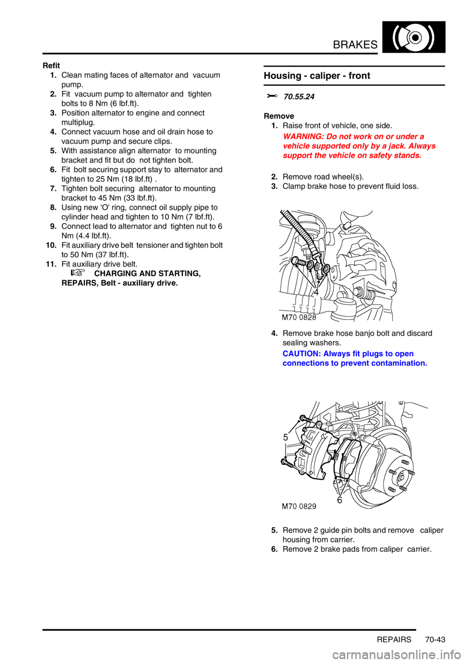
3.Clamp brake hose to prevent fluid loss.
4.Remove brake hose banjo bolt and discard
sealing washers.
CAUTION: Always fit plugs to open
connections to prevent contamination.
5.Remove 2 guide pin bolts and remove caliper
housing from carrier.
6.Remove 2 brake pads from caliper carrier.
Page 1218 of 1672
SUNROOF
DESCRIPTION AND OPERATION 76-6-3
1Glass panel
2Nut - glass panel
3Frame - glass panel
4Bolt - glass panel
5Drive cables and lifting assembly
6Screw - glass panel frame
7Sunroof frame
8Sunroof blind
9Screw - sunroof frame
10Drain tubes
11Screw - motor
12Motor and gearbox
13Spacer - manual sunroof regulator
14Regulator - manual sunroof
15Handle - manual sunroof
16Screw - manual sunroof regulator
17Screw - manual sunroof handle
Page 1362 of 1672
HEATING AND VENTILATION
REPAIRS 80-21
Refit
1.Fit plenum air intake.
2.Fit trim clips and centre bolt securing plenum
air intake to body.
3.Fit rubber spacers and washers to wiper
linkage.
4.Fit locknuts to wiper linkage and tighten to 7
Nm (5.2 lbf.ft).
5.Fit wiper arms to wiper linkage.
6.Fit nuts securing wiper arms to wiper linkage
and tighten to 15 Nm (11 lbf.ft).
7.Fit caps to wiper arms.
8.Fit both windscreen side finishers.
+ EXTERIOR FITTINGS, REPAIRS,
Side finisher - windscreen.
Heater assembly - models without air
conditioning
$% 80.20.01.99
Remove
1.Drain cooling system.
l
+ COOLING SYSTEM - Td5,
ADJUSTMENTS, Drain and refill.
l
+ COOLING SYSTEM - V8,
ADJUSTMENTS, Drain and refill.
2. Diesel models: Remove 3 bolts and remove
engine cover.
3.Release clips and disconnect coolant hoses
from heater pipes.
CAUTION: Always fit plugs to open
connections to prevent contamination.
4.Remove facia assembly.
+ INTERIOR TRIM COMPONENTS,
REPAIRS, Fascia.
Page 1363 of 1672
HEATING AND VENTILATION
80-22REPAIRS
5.Disconnect harness multiplug from heater
blower motor.
6.Remove bolt and 2 nuts securing heater
blower housing assembly to body and remove
blower.
7.Disconnect 2 drain tubes from base of heater. 8.Remove 2 screws securing console bracket to
tunnel and remove bracket.
9.Release radio coaxial cable from behind heater
pipes.
10.Protect the carpet from coolant spillage.
11.Remove 4 nuts and 1 bolt securing heater to
body.
12.Remove heater from vehicle.
13.Remove 2 screws securing heater RH and LH
footwell outlet duct to heater casing and
remove ducts.
Page 1364 of 1672

HEATING AND VENTILATION
REPAIRS 80-23
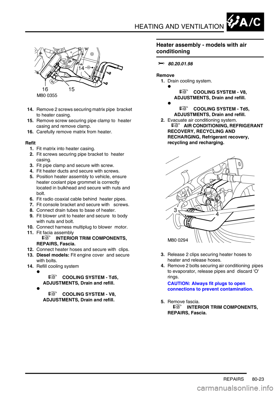
14.Remove 2 screws securing matrix pipe bracket
to heater casing.
15.Remove screw securing pipe clamp to heater
casing and remove clamp.
16.Carefully remove matrix from heater.
Refit
1.Fit matrix into heater casing.
2.Fit screws securing pipe bracket to heater
casing.
3.Fit pipe clamp and secure with screw.
4.Fit heater ducts and secure with screws.
5.Position heater assembly to vehicle, ensure
heater coolant pipe grommet is correctly
located in bulkhead and secure with nuts and
bolt.
6.Fit radio coaxial cable behind heater pipes.
7.Fit console bracket and secure with screws.
8.Connect drain tubes to base of heater.
9.Fit blower unit to heater and secure to body
with nuts and bolt.
10.Connect harness multiplug to blower motor.
11.Fit facia assembly
+ INTERIOR TRIM COMPONENTS,
REPAIRS, Fascia.
12.Connect heater hoses and secure with clips.
13. Diesel models: Fit engine cover and secure
with bolts.
14.Refill cooling system
l
+ COOLING SYSTEM - Td5,
ADJUSTMENTS, Drain and refill.
l
+ COOLING SYSTEM - V8,
ADJUSTMENTS, Drain and refill.
Heater assembly - models with air
conditioning
$% 80.20.01.98
Remove
1.Drain cooling system.
l
+ COOLING SYSTEM - V8,
ADJUSTMENTS, Drain and refill.
l
+ COOLING SYSTEM - Td5,
ADJUSTMENTS, Drain and refill.
2.Evacuate air conditioning system.
+ AIR CONDITIONING, REFRIGERANT
RECOVERY, RECYCLING AND
RECHARGING, Refrigerant recovery,
recycling and recharging.
3.Release 2 clips securing heater hoses to
heater and release hoses.
4.Remove 2 bolts securing air conditioning pipes
to evaporator, release pipes and discard 'O'
rings.
CAUTION: Always fit plugs to open
connections to prevent contamination.
5.Remove fascia.
+ INTERIOR TRIM COMPONENTS,
REPAIRS, Fascia.