Page 87 of 1672

TORQUE WRENCH SETTINGS
06-2
Engine Td5
TORQUE DESCRIPTION METRIC IMPERIAL
ACE pump bolts25 Nm (18 lbf.ft)
A/C compressor bolts 25 Nm (18 lbf.ft)
Alternator support bracket to cylinder head bolts 25 Nm (18 lbf.ft)
Alternator/vacuum pump oil feed pipe union 10 Nm (7 lbf.ft)
Camshaft cover to camshaft carrier bolts 10 Nm (7 lbf.ft)
Camshaft sprocket to camshaft bolts 37 Nm (27 lbf.ft)
Centrifuge cover bolts 10 Nm (7 lbf.ft)
Centrifuge oil drain pipe to sump bolts (or nuts) 10 Nm (7 lbf.ft)
Centrifuge to oil drain pipe bolts 10 Nm (7 lbf.ft)
Centrifuge to oil cooler housing bolts 25 Nm (18 lbf.ft)
CKP sensor bolt10 Nm (7 lbf.ft)
Coolant pipe bolt50 Nm (37 lbf.ft)
Connecting rod bolts, then a further 80°20 Nm (15 lbf.ft)
Crankshaft pulley bolt 460 Nm (340 lbf.ft)
Crankshaft pulley TV damper bolts 80 Nm (59 lbf.ft)
Crankshaft rear oil seal housing bolts 10 Nm (7 lbf.ft)
Cylinder head bolts initial tighten 30 Nm (22 lbf.ft)
Cylinder head bolts final tighten, then a further 90°, then a further 180° and finally a
further 45°65 Nm (48 lbf.ft)
Dipstick tube to camshaft carrier bolt 10 Nm (7 lbf.ft)
Drive plate (automatic transmission) to crankshaft bolts 115 Nm (85 lbf.ft)
EGR pipe clamp to cylinder head bolt - if fitted 25 Nm (18 lbf.ft)
EGR pipe Allen screws 10 Nm (7 lbf.ft)
Engine mounting (front) to cylinder block bolts 48 Nm (35 lbf.ft)
Engine mounting (front) to chassis nuts 85 Nm (63 lbf.ft)
Engine mounting bracket (rear, LH & RH) to gearbox bolts 85 Nm (63 lbf.ft)
Engine mounting bracket (rear, LH & RH) nuts 45 Nm (33 lbf.ft)
Flywheel to crankshaft (manual transmission) bolts, then a further 90°40 Nm (30 lbf.ft)
Front crossmember bolts 26 Nm (20 lbf.ft)
Fuel connector block bolts 25 Nm (18 lbf.ft)
Fuel cooler to inlet manifold bolts 25 Nm (18 lbf.ft)
Gearbox housing to engine bolts 50 Nm (37 lbf.ft)
Heater pipe to cylinder head bolts 25 Nm (18 lbf.ft)
Main bearing cap bolts then a further 90°33 Nm (24 lbf.ft)
Oil cooler housing to cylinder block bolts 25 Nm (18 lbf.ft)
Oil cooler pipe clip bolts 10 Nm (7 lbf.ft)
Oil filter adaptor housing to oil cooler housing bolts 25 Nm (18 lbf.ft)
Oil pick-up strainer screws 10 Nm (7 lbf.ft)
Oil pressure switch 15 Nm (11 lbf.ft)
Oil pump drive sprocket bolt 25 Nm (18 lbf.ft)
Oil pump pressure relief valve plug 25 Nm (18 lbf.ft)
Oil pump and stiffener assembly to cylinder block bolts 13 Nm (10 lbf.ft)
Oil sump to cylinder block bolts 25 Nm (18 lbf.ft)
Oil sump to gearbox bell housing bolts 13 Nm (10 lbf.ft)
PAS pump bracket bolts 27 Nm (20 lbf.ft)
PAS pump pulley bolts 27 Nm (20 lbf.ft)
Rocker arm adjusting screw locknuts 16 Nm (12 lbf.ft)
Page 110 of 1672
MAINTENANCE
PROCEDURES 10-1
MAINTENANCE PROCEDURES
V8 engine underbonnet view
1Brake/clutch fluid reservoir filler caps
2Engine oil filler cap
3Spark plug
4Engine oil dipstick
5Coolant header tank
6Battery
7Auxiliary drive belt
8ACE/PAS fluid reservoirs
9Windscreen washer reservoir
Page 111 of 1672
MAINTENANCE
10-2 PROCEDURES
Diesel underbonnet view
1Coolant header tank
2Brake/clutch fluid reservoir filler caps
3Engine oil dipstick
4Engine oil filler cap
5ACE/PAS fluid reservoirs
6Battery
7Auxiliary drive belt
8Air cleaner
9Windscreen washer reservoir
Page 123 of 1672

MAINTENANCE
10-14 PROCEDURES
Intercooler - diesel engine
Remove
1.Remove intercooler.
+ ENGINE MANAGEMENT SYSTEM -
Td5, REPAIRS, Intercooler.
Flush
1.Flush intercooler element using Flushing
Solvent Part No. STC 9713, following the
manufacturer's instructions.
2.Thoroughly dry intercooler ensuring that no
trace of solvent remains in the element.
3.Refit intercooler on completion.
+ ENGINE MANAGEMENT SYSTEM -
Td5, REPAIRS, Intercooler.
Engine oil - V8 engine
WARNING: Avoid excessive skin contact with
used engine oil. Used engine oil contains
potentially harmful contaminants which may
cause skin cancer or other serious skin
disorders.
Replace
1.Position suitable container beneath sump.
2.Clean area around oil drain plug.
3.Remove oil drain plug, discard sealing washer.
4.Allow oil to drain.
5.Fit new sealing washer to oil drain plug.
6.Fit engine drain plug and tighten to 33 Nm (24
lbf.ft).
7.Fill engine with recommended grade of oil to
correct mark on dipstick.
+ CAPACITIES, FLUIDS AND
LUBRICANTS, Lubrication.
Engine oil - diesel engine
WARNING: Avoid excessive skin contact with
used engine oil. Used engine oil contains
potentially harmful contaminants which may
cause skin cancer or other serious skin
disorders.
Replace
1.Release fixings, remove underbelly panel.
2.Position suitable container beneath sump.
3.Clean area around drain plug.
4.Remove oil drain plug, discard sealing washer.
5.Allow oil to drain.
6.Fit new sealing washer to oil drain plug.
7.Fit engine drain plug and tighten to 23 Nm (17
lbf.ft).
8.Fill engine with recommended grade of oil to
correct mark on dipstick.
+ CAPACITIES, FLUIDS AND
LUBRICANTS, Lubrication.
9.Fit front underbelly panel, secure fixings.
Page 124 of 1672

MAINTENANCE
PROCEDURES 10-15
Centrifuge rotor – diesel engine
Replace
1.Replace centrifuge rotor.
+ ENGINE - Td5, REPAIRS, Rotor -
centrifuge.
Engine oil filter - diesel engine
Replace
1.Replace oil filter.
+ ENGINE - Td5, REPAIRS, Filter - oil.
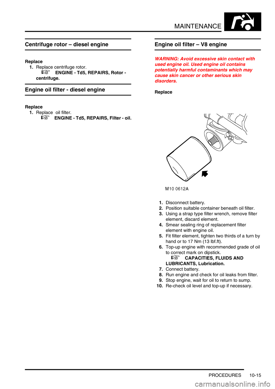
Engine oil filter – V8 engine
WARNING: Avoid excessive skin contact with
used engine oil. Used engine oil contains
potentially harmful contaminants which may
cause skin cancer or other serious skin
disorders.
Replace
1.Disconnect battery.
2.Position suitable container beneath oil filter.
3.Using a strap type filter wrench, remove filter
element, discard element.
4.Smear sealing ring of replacement filter
element with engine oil.
5.Fit filter element, tighten two thirds of a turn by
hand or to 17 Nm (13 lbf.ft).
6.Top-up engine with recommended grade of oil
to correct mark on dipstick.
+ CAPACITIES, FLUIDS AND
LUBRICANTS, Lubrication.
7.Connect battery.
8.Run engine and check for oil leaks from filter.
9.Stop engine, wait for oil to return to sump.
10.Re-check oil level and top-up if necessary.
Page 142 of 1672

ENGINE - TD5
DESCRIPTION AND OPERATION 12-1-3
1Oil dipstick tube
2Screw – oil dipstick tube to camshaft carrier
3Oil dipstick
42nd piston ring
5Piston
6Small-end bush
7Connecting rod
8Big-end bearing cap
9Connecting rod bolt (2 off per connecting rod)
10Top piston ring
11Oil control ring
12Circlips (2 off per gudgeon pin)
13Gudgeon pin
14Big-end bearing shells
15Dowels – cylinder head (2 off)
16Clutch housing shim plate
17 Crankshaft rear oil seal and housing
18Screws – crankshaft seal housing to engine
block (5 off)
19Bolts – clutch housing shim plate to engine
block (2 off)
20Main oil gallery plug (rear)
21Oil filter adaptor gasket
22Oil filter adaptor thermostat
23Oil filter adaptor assembly
24Oil filter adaptor insert25Oil filter adaptor to cylinder block bolts (3 off)
26Oil filter
27Oil pressure switch
28Oil cooler banjo bolts (2 off)
29O-rings – oil cooler banjo bolts (2 off)
30Oil cooler to cylinder block bolts (7 off)
31Centrifuge assembly
32Centrifuge to cylinder block bolts (3 off)
33Centrifuge oil drain pipe
34Oil drain pipe to sump gasket
35Centrifuge to oil drain pipe gasket
36Oil cooler plugs (3 off)
37Oil cooler assembly
38Oil cooler matrix 'O-rings' (2 off)
39Oil cooler matrix
40Oil cooler gasket
41Coolant and PAS pump assembly bracket
42Bracket bolts (5 off + 1 stud/nut)
43Cylinder block
44Dowels to timing block cover (2 off)
45Oil gallery delivery plug
46Cross drilling plug
47Coolant jacket plug
48Core plugs (3 off)
Page 248 of 1672

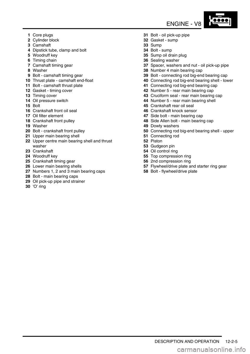
ENGINE - V8
DESCRIPTION AND OPERATION 12-2-5
1Core plugs
2Cylinder block
3Camshaft
4Dipstick tube, clamp and bolt
5Woodruff key
6Timing chain
7Camshaft timing gear
8Washer
9Bolt - camshaft timing gear
10Thrust plate - camshaft end-float
11Bolt - camshaft thrust plate
12Gasket - timing cover
13Timing cover
14Oil pressure switch
15Bolt
16Crankshaft front oil seal
17Oil filter element
18Crankshaft front pulley
19Washer
20Bolt - crankshaft front pulley
21Upper main bearing shell
22Upper centre main bearing shell and thrust
washer
23Crankshaft
24Woodruff key
25Crankshaft timing gear
26Lower main bearing shells
27Numbers 1, 2 and 3 main bearing caps
28Bolt - main bearing caps
29Oil pick-up pipe and strainer
30'O' ring31Bolt - oil pick-up pipe
32Gasket - sump
33Sump
34Bolt - sump
35Sump oil drain plug
36Sealing washer
37Spacer, washers and nut - oil pick-up pipe
38Number 4 main bearing cap
39Bolt - connecting rod big-end bearing cap
40Connecting rod big-end bearing shell - lower
41Connecting rod big-end bearing cap
42Number 5 - rear main bearing cap
43Cruciform seal - rear main bearing cap
44Number 5 - rear main bearing shell
45Crankshaft rear oil seal
46Crankshaft knock sensor
47Side bolt - main bearing cap
48Side Allen bolt - main bearing cap
49Dowty washers
50Connecting rod big-end bearing shell - upper
51Connecting rod
52Piston
53Gudgeon pin
54Oil control ring
55Top compression ring
562nd compression ring
57Flywheel/drive plate and starter ring gear
58Bolt - flywheel/drive plate
Page 279 of 1672
ENGINE - V8
12-2-36 REPAIRS
8.Clean coolant pump and mating face.
9.Use a new gasket and fit coolant pump.
Tighten bolts securing coolant pump to 25 Nm
(19 lbf.ft).
10.Ensure CMP sensor is clean and fit sensor to
cover.
11.Fit clamp to CMP sensor and tighten bolt to 8
Nm (6 lbf.ft).
12.Fit timing gear cover gasket.
+ ENGINE - V8, REPAIRS, Gasket -
timing gear cover.
Gasket - sump
$% 12.60.38
Remove
1.Release fixings and remove battery cover.
2.Disconnect battery earth lead.
3.Remove dipstick.
4.Raise the vehicle on a ramp.
5.Drain engine oil.
+ MAINTENANCE, PROCEDURES,
Engine oil - V8 engine.
6.Remove 8 bolts securing cross member and
remove cross member.
7.Raise front of vehicle under body to increase
clearance between engine and front axle.
8.Disconnect and release gearbox oil cooler pipe
and discard 'O' ring.