2002 LAND ROVER DISCOVERY fold seats
[x] Cancel search: fold seatsPage 5 of 1672

CONTENTS
2CONTENTS
IDENTIFICATION NUMBERS .................................................................. 05-1
Vehicle Identification Number ......................................................................................................... 05-1
Identification Number Locations ..................................................................................................... 05-3
TORQUE WRENCH SETTINGS .............................................................. 06-1
Maintenance ................................................................................................................................... 06-1
Engine Td5 ..................................................................................................................................... 06-2
Engine V8 ....................................................................................................................................... 06-4
Emission control - Td5 .................................................................................................................... 06-5
Emission control - V8 ...................................................................................................................... 06-5
Engine management system - Td5 ................................................................................................. 06-5
Engine management system - V8................................................................................................... 06-6
Cooling system ............................................................................................................................... 06-6
Manifolds and exhaust systems - Td5 ............................................................................................ 06-6
Manifolds and exhaust systems - V8 .............................................................................................. 06-7
Clutch.............................................................................................................................................. 06-7
Manual gearbox - R380 .................................................................................................................. 06-8
Transfer box - LT230SE ................................................................................................................. 06-8
Automatic gearbox - ZF4HP22/24 .................................................................................................. 06-9
Propeller shafts ............................................................................................................................... 06-9
Axles ............................................................................................................................................... 06-9
Steering .......................................................................................................................................... 06-10
Front suspension ............................................................................................................................ 06-11
Rear suspension ............................................................................................................................. 06-12
Brakes............................................................................................................................................. 06-12
Restraint systems ........................................................................................................................... 06-13
Body................................................................................................................................................ 06-14
Heating and air conditioning ........................................................................................................... 06-15
Wipers and washers ....................................................................................................................... 06-15
Electrical ......................................................................................................................................... 06-15
LIFTING AND TOWING ........................................................................... 08-1
LIFTING .......................................................................................................................................... 08-1
TOWING ......................................................................................................................................... 08-2
TRANSPORTING ........................................................................................................................... 08-3
CAPACITIES, FLUIDS AND LUBRICANTS ............................................ 09-1
Capacities ....................................................................................................................................... 09-1
Fluids .............................................................................................................................................. 09-2
Anti-Freeze Concentration .............................................................................................................. 09-3
Lubrication ...................................................................................................................................... 09-3
MAINTENANCE ........................................................................................ 10-1
PROCEDURES
V8 engine underbonnet view .......................................................................................................... 10-1
Diesel underbonnet view ................................................................................................................ 10-2
Seats and seat belts ...................................................................................................................... 10-3
Lamps, horns and warning indicators ........................................................................................... 10-5
Wipers and washers ...................................................................................................................... 10-5
Handbrake .................................................................................................................................. 10-6
Page 196 of 1672

ENGINE - TD5
REPAIRS 12-1-57
Filter - oil
$% 12.60.04
Remove
1.Remove 3 bolts and remove engine acoustic
cover.
2.Remove 3 bolts and remove exhaust manifold
heat shield.
3.Clean area around filter head and place a
container beneath engine.
4.Using a strap wrench, unscrew and discard
filter. Refit
1.Clean mating face of filter head.
2.Lubricate sealing ring of new filter with clean
engine oil.
3.Fit filter and tighten by hand until it seats then
tighten a further three-quarters of a turn.
4.Start and run engine to check for leaks.
5.Stop engine, wait a few minutes, then check oil
level.
6.Top up engine oil.
+ MAINTENANCE, PROCEDURES,
Engine oil - diesel engine.
7.Position exhaust manifold heatshield and
tighten M6 bolts to 9 Nm (7 lbf.ft) and M8 bolts
to 25 Nm (18 lbf.ft).
8.Fit engine acoustic cover and secure with
fixings.
Page 574 of 1672

FUEL DELIVERY SYSTEM - V8
DESCRIPTION AND OPERATION 19-2-9
Injectors
1'O' ring 2 off
2Electrical connector
3Steel housing
4Filter strainer
5Spring6Valve needle and armature
7Valve seat/spray orifice
8Plastic housing
9Solenoid winding
An injector for each cylinder is mounted externally in the lower inlet manifold on the engine. The injector protrudes
into the inlet manifold tract, where it releases a controlled delivery of fuel into the manifold air inlet.
Each injector is sealed to the fuel rail and the inlet manifold with 'O' rings. Spring clips retain each injector to the fuel
rail and the attachment of the fuel rail clamps the injectors in the lower manifold.
The injector housing is manufactured from plastic which encapsulates a high-alloy steel housing. The steel housing
contains all components which come into contact with fuel. The plastic housing also provides the attachment for the
engine harness connector for the injector. A solenoid is located between the two housings and moves a valve needle
via an armature. The valve needle seats on a valve seat which incorporates a spray orifice plate. A filter strainer is
fitted at the connection with the fuel rail to remove any particulate matter from the fuel before it enters the injector.
When the ECM energises the solenoid, the armature moves lifting the valve needle off its seat. This allows
pressurised fuel from the fuel rail to pass through the injector housing and needle to the spray orifice. The spray orifice
controls the spray shape and fuel metering. When the solenoid is de-energised, the valve needle returns to the valve
seat, aided by a spring, closing off the injection of fuel into the inlet.
Each injector receives a battery supply voltage via a fuse in the engine compartment fusebox. The fuel delivery timing
is controlled by the ECM, which, at a precisely timed interval, provides a ground path for the injector. The completion
of the ground path operates the injector to allow fuel at pump pressure to be delivered from the fuel rail to the injector
nozzle. Each injector sprays a finely atomized spray of fuel into the inlet, where it is mixed with the intake air prior to
combustion.
+ ENGINE MANAGEMENT SYSTEM - V8, DESCRIPTION AND OPERATION, Description - engine
management.
Faults for each injector are stored in the ECM and can be retrieved using TestBook. Each injector can be checked
across the two connector pins. For a correctly functioning injector a resistance of between 13.8 and 15.2 ohms at a
temperature of 20
°C (65°F) should be read across the pins.
Page 1108 of 1672
RESTRAINT SYSTEMS
REPAIRS 75-13
REPAIRS
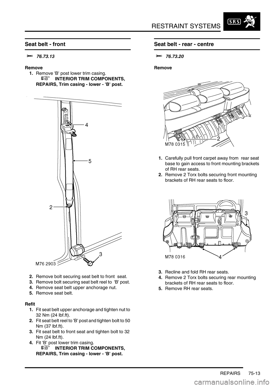
Seat belt - front
$% 76.73.13
Remove
1.Remove 'B' post lower trim casing.
+ INTERIOR TRIM COMPONENTS,
REPAIRS, Trim casing - lower - 'B' post.
2.Remove bolt securing seat belt to front seat.
3.Remove bolt securing seat belt reel to 'B' post.
4.Remove seat belt upper anchorage nut.
5.Remove seat belt.
Refit
1.Fit seat belt upper anchorage and tighten nut to
32 Nm (24 lbf.ft).
2.Fit seat belt reel to 'B' post and tighten bolt to 50
Nm (37 lbf.ft).
3.Fit seat belt to front seat and tighten bolt to 32
Nm (24 lbf.ft).
4.Fit 'B' post lower trim casing.
+ INTERIOR TRIM COMPONENTS,
REPAIRS, Trim casing - lower - 'B' post.
Seat belt - rear - centre
$% 76.73.20
Remove
1.Carefully pull front carpet away from rear seat
base to gain access to front mounting brackets
of RH rear seats.
2.Remove 2 Torx bolts securing front mounting
brackets of RH rear seats to floor.
3.Recline and fold RH rear seats.
4.Remove 2 Torx bolts securing rear mounting
brackets of RH rear seats to floor.
5.Remove RH rear seats.
Page 1156 of 1672
INTERIOR TRIM COMPONENTS
REPAIRS 76-3-3
Trim casing - lower - 'B' post
$% 76.13.29
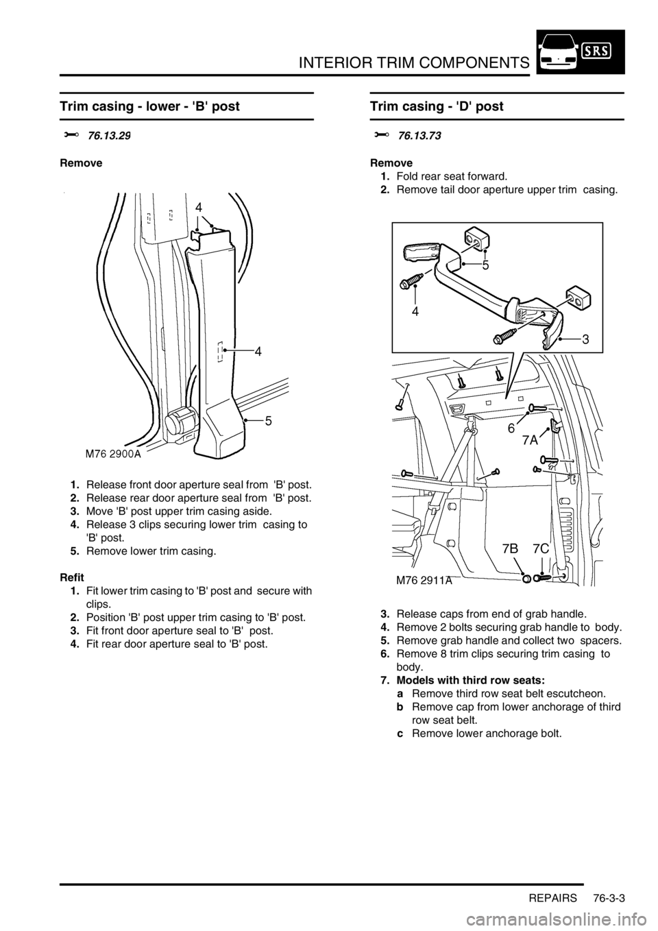
Remove
1.Release front door aperture seal from 'B' post.
2.Release rear door aperture seal from 'B' post.
3.Move 'B' post upper trim casing aside.
4.Release 3 clips securing lower trim casing to
'B' post.
5.Remove lower trim casing.
Refit
1.Fit lower trim casing to 'B' post and secure with
clips.
2.Position 'B' post upper trim casing to 'B' post.
3.Fit front door aperture seal to 'B' post.
4.Fit rear door aperture seal to 'B' post.
Trim casing - 'D' post
$% 76.13.73
Remove
1.Fold rear seat forward.
2.Remove tail door aperture upper trim casing.
3.Release caps from end of grab handle.
4.Remove 2 bolts securing grab handle to body.
5.Remove grab handle and collect two spacers.
6.Remove 8 trim clips securing trim casing to
body.
7. Models with third row seats:
aRemove third row seat belt escutcheon.
bRemove cap from lower anchorage of third
row seat belt.
cRemove lower anchorage bolt.
Page 1202 of 1672
SEATS
REPAIRS 76-5-17
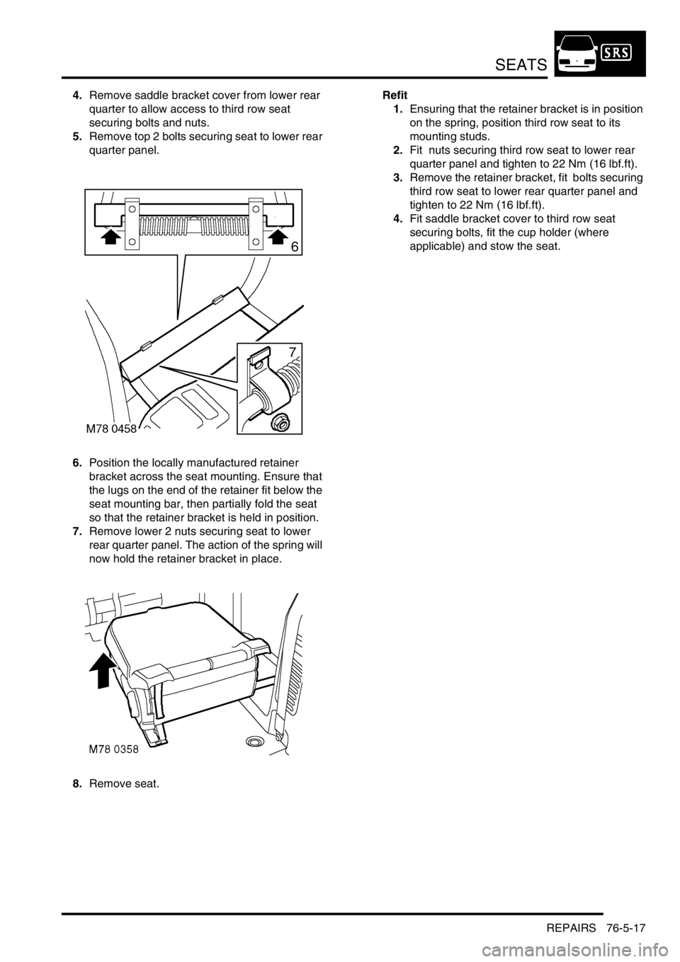
4.Remove saddle bracket cover from lower rear
quarter to allow access to third row seat
securing bolts and nuts.
5.Remove top 2 bolts securing seat to lower rear
quarter panel.
6.Position the locally manufactured retainer
bracket across the seat mounting. Ensure that
the lugs on the end of the retainer fit below the
seat mounting bar, then partially fold the seat
so that the retainer bracket is held in position.
7.Remove lower 2 nuts securing seat to lower
rear quarter panel. The action of the spring will
now hold the retainer bracket in place.
8.Remove seat.Refit
1.Ensuring that the retainer bracket is in position
on the spring, position third row seat to its
mounting studs.
2.Fit nuts securing third row seat to lower rear
quarter panel and tighten to 22 Nm (16 lbf.ft).
3.Remove the retainer bracket, fit bolts securing
third row seat to lower rear quarter panel and
tighten to 22 Nm (16 lbf.ft).
4.Fit saddle bracket cover to third row seat
securing bolts, fit the cup holder (where
applicable) and stow the seat.
Page 1203 of 1672
SEATS
76-5-18 REPAIRS
Seat - rear
$% 78.10.48.99
This procedure is applicable to both rear seats.
Remove
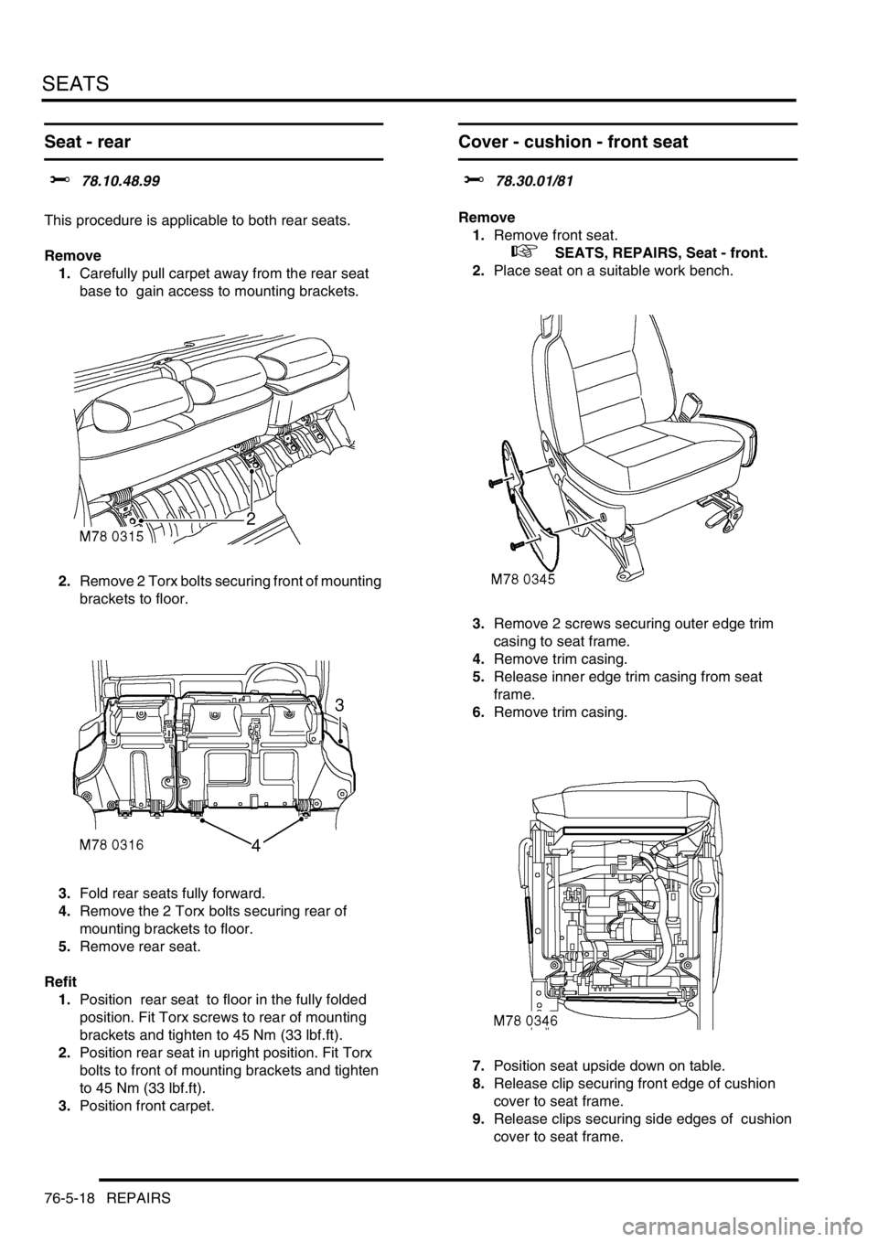
1.Carefully pull carpet away from the rear seat
base to gain access to mounting brackets.
2.Remove 2 Torx bolts securing front of mounting
brackets to floor.
3.Fold rear seats fully forward.
4.Remove the 2 Torx bolts securing rear of
mounting brackets to floor.
5.Remove rear seat.
Refit
1.Position rear seat to floor in the fully folded
position. Fit Torx screws to rear of mounting
brackets and tighten to 45 Nm (33 lbf.ft).
2.Position rear seat in upright position. Fit Torx
bolts to front of mounting brackets and tighten
to 45 Nm (33 lbf.ft).
3.Position front carpet.
Cover - cushion - front seat
$% 78.30.01/81
Remove
1.Remove front seat.
+ SEATS, REPAIRS, Seat - front.
2.Place seat on a suitable work bench.
3.Remove 2 screws securing outer edge trim
casing to seat frame.
4.Remove trim casing.
5.Release inner edge trim casing from seat
frame.
6.Remove trim casing.
7.Position seat upside down on table.
8.Release clip securing front edge of cushion
cover to seat frame.
9.Release clips securing side edges of cushion
cover to seat frame.
Page 1211 of 1672
SEATS
76-5-26 REPAIRS
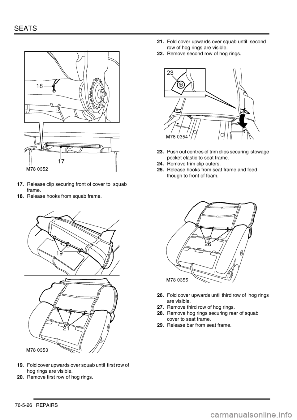
17.Release clip securing front of cover to squab
frame.
18.Release hooks from squab frame.
19.Fold cover upwards over squab until first row of
hog rings are visible.
20.Remove first row of hog rings. 21.Fold cover upwards over squab until second
row of hog rings are visible.
22.Remove second row of hog rings.
23.Push out centres of trim clips securing stowage
pocket elastic to seat frame.
24.Remove trim clip outers.
25.Release hooks from seat frame and feed
though to front of foam.
26.Fold cover upwards until third row of hog rings
are visible.
27.Remove third row of hog rings.
28.Remove hog rings securing rear of squab
cover to seat frame.
29.Release bar from seat frame.