2002 JEEP LIBERTY Serpentine belt
[x] Cancel search: Serpentine beltPage 230 of 1803
ACCESSORY DRIVE
TABLE OF CONTENTS
page page
ACCESSORY DRIVE
DIAGNOSIS AND TESTING - SERPENTINE
DRIVE BELT.........................15
BELT TENSIONERS
REMOVAL - 3.7L ENGINE.................17INSTALLATION - 3.7L ENGINE.............17
DRIVE BELTS - 3.7L
REMOVAL - 3.7L ENGINE.................17
INSTALLATION - 3.7L ENGINE.............18
ACCESSORY DRIVE
DIAGNOSIS AND TESTING - SERPENTINE
DRIVE BELT
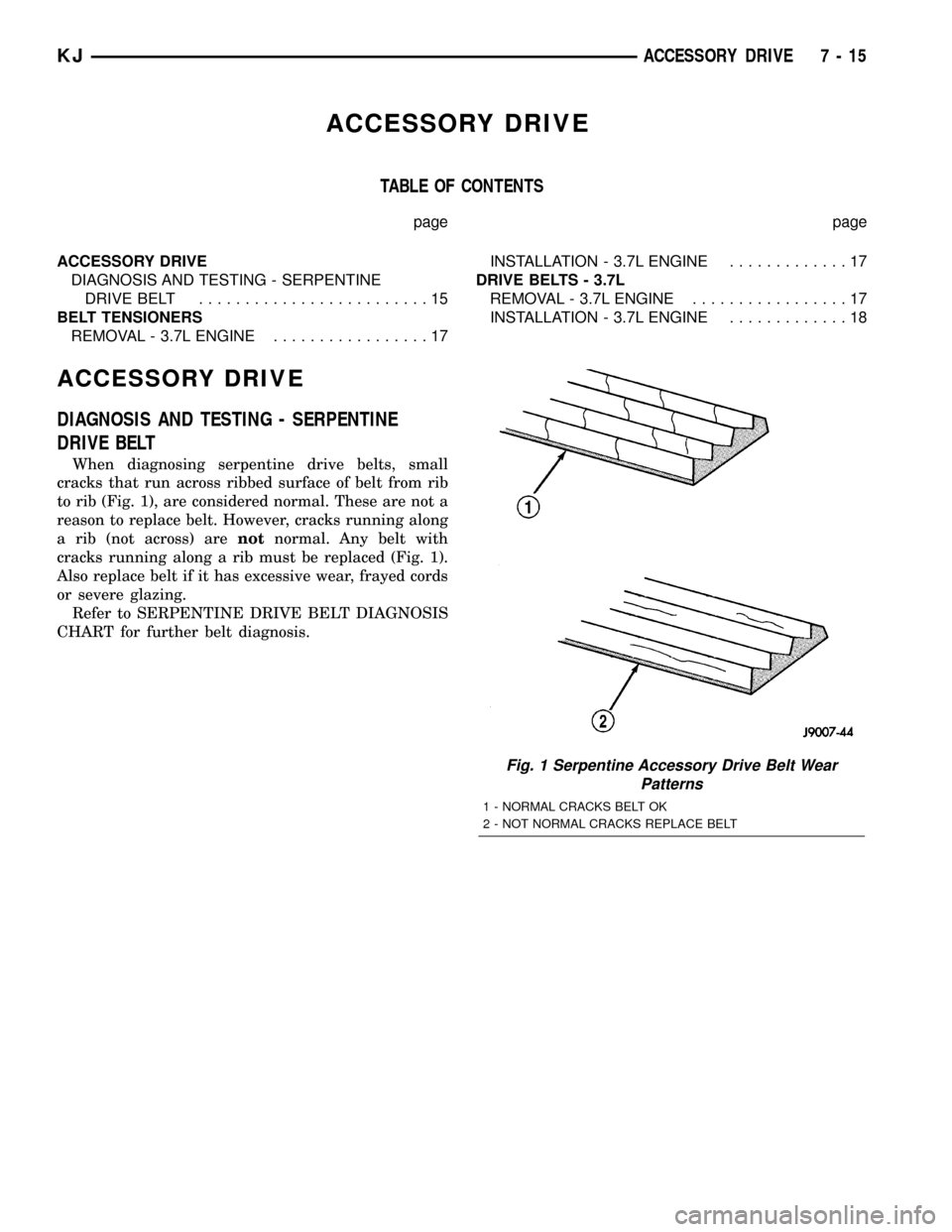
When diagnosing serpentine drive belts, small
cracks that run across ribbed surface of belt from rib
to rib (Fig. 1), are considered normal. These are not a
reason to replace belt. However, cracks running along
a rib (not across) arenotnormal. Any belt with
cracks running along a rib must be replaced (Fig. 1).
Also replace belt if it has excessive wear, frayed cords
or severe glazing.
Refer to SERPENTINE DRIVE BELT DIAGNOSIS
CHART for further belt diagnosis.
Fig. 1 Serpentine Accessory Drive Belt Wear
Patterns
1 - NORMAL CRACKS BELT OK
2 - NOT NORMAL CRACKS REPLACE BELT
KJACCESSORY DRIVE 7 - 15
Page 231 of 1803
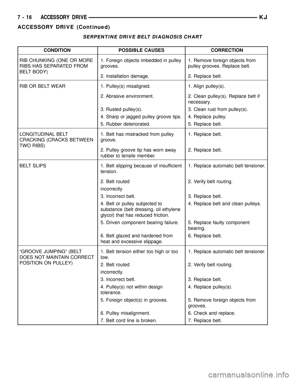
SERPENTINE DRIVE BELT DIAGNOSIS CHART
CONDITION POSSIBLE CAUSES CORRECTION
RIB CHUNKING (ONE OR MORE
RIBS HAS SEPARATED FROM
BELT BODY)1. Foreign objects imbedded in pulley
grooves.1. Remove foreign objects from
pulley grooves. Replace belt.
2. Installation damage. 2. Replace belt.
RIB OR BELT WEAR 1. Pulley(s) misaligned. 1. Align pulley(s).
2. Abrasive environment. 2. Clean pulley(s). Replace belt if
necessary.
3. Rusted pulley(s). 3. Clean rust from pulley(s).
4. Sharp or jagged pulley groove tips. 4. Replace pulley.
5. Rubber deteriorated. 5. Replace belt.
LONGITUDINAL BELT
CRACKING (CRACKS BETWEEN
TWO RIBS)1. Belt has mistracked from pulley
groove.1. Replace belt.
2. Pulley groove tip has worn away
rubber to tensile member.2. Replace belt.
BELT SLIPS 1. Belt slipping because of insufficient
tension.1. Replace automatic belt tensioner.
2. Belt routed 2. Verify belt routing.
incorrectly
3. Incorrect belt. 3. Replace belt.
4. Belt or pulley subjected to
substance (belt dressing, oil ethylene
glycol) that has reduced friction.4. Replace belt and clean pulleys.
5. Driven component bearing failure. 5. Replace faulty component
bearing.
6. Belt glazed and hardened from
heat and excessive slippage.6. Replace belt.
ªGROOVE JUMPING9(BELT
DOES NOT MAINTAIN CORRECT
POSITION ON PULLEY)1. Belt tension either too high or too
low.1. Replace automatic belt tensioner.
2. Belt routed 2. Verify belt routing.
incorrectly.
3. Incorrect belt. 3. Replace belt.
4. Pulley(s) not within design
tolerance.4. Replace pulley(s).
5. Foreign object(s) in grooves. 5. Remove foreign objects from
grooves.
6. Pulley misalignment. 6. Check and replace.
7. Belt cord line is broken. 7. Replace belt.
7 - 16 ACCESSORY DRIVEKJ
ACCESSORY DRIVE (Continued)
Page 233 of 1803

CAUTION: DO NOT LET TENSIONER ARM SNAP
BACK TO THE FREEARM POSITION, SEVERE DAM-
AGE MAY OCCUR TO THE TENSIONER.
Belt tension is not adjustable. Belt adjustment is
maintained by an automatic ( spring load ) belt ten-
sioner.
(1) Disconnect negative battery cable from battery.
(2) Rotate belt tensioner until it contacts its stop.
Remove belt, then slowly rotate the tensioner into
the freearm position. (Fig. 3).INSTALLATION - 3.7L ENGINE
NOTE: The belt routing schematics are published
from the latest information available at the time of
publication. If anything differs between these sche-
matics and the Belt Routing Label, use the sche-
matics on Belt Routing Label. This label is located
in the engine compartment.
Belt tension is not adjustable. Belt adjustment is
maintained by an automatic ( spring load ) belt ten-
sioner.
(1) Check condition of all pulleys.
CAUTION: When installing the serpentine accessory
drive belt, the belt MUST be routed correctly. If not,
the engine may overheat due to the water pump
rotating in the wrong direction (Fig. 3).
(2) Install new belt (Fig. 3). Route the belt around
all pulleys except the idler pulley. Rotate the ten-
sioner arm until it contacts its stop position. Route
the belt around the idler and slowly let the tensioner
rotate into the belt. Make sure the belt is seated onto
all pulleys.
(3) With the drive belt installed, inspect the belt
wear indicator (Fig. 4). On 3.7L Engines the gap
between the tang and the housing stop ( measure-
ment A ) must not exceed 24 mm (.94 inches).
Fig. 3 Belt Routing - 3.7L
1 - GENERATOR PULLEY
2 - ACCESSORY DRIVE BELT
3 - POWER STEERING PUMP PULLEY
4 - CRANKSHAFT PULLEY
5 - IDLER PULLEY
6 - TENSIONER
7 - A/C COMPRESSOR PULLEY
8 - WATER PUMP PULLEY
Fig. 4 Accessory Drive Belt Wear Indicator
1 - AUTOMATIC TENSIONER ASSEMBLY
7 - 18 ACCESSORY DRIVEKJ
DRIVE BELTS - 3.7L (Continued)
Page 244 of 1803

CAUTION: Do not remove water pump pulley-to-wa-
ter pump bolts. This pulley is under belt tension.
(8) Remove four bolts securing fan blade assembly
to viscous fan drive.
CLEANING
Clean the fan blades using a mild soap and water.
Do not use an abrasive to clean the blades.
INSPECTION
WARNING: DO NOT ATTEMPT TO BEND OR
STRAIGHTEN FAN BLADES IF FAN IS NOT WITHIN
SPECIFICATIONS.
CAUTION: If fan blade assembly is replaced
because of mechanical damage, water pump and
viscous fan drive should also be inspected. These
components could have been damaged due to
excessive vibration.
(1) Remove fan blade assembly from viscous fan
drive unit (four bolts).
(2) Lay fan on a flat surface with leading edge fac-
ing down. With tip of blade touching flat surface,
replace fan if clearance between opposite blade and
surface is greater than 2.0 mm (.090 inch). Rocking
motion of opposite blades should not exceed 2.0 mm
(.090 inch). Test all blades in this manner.
(3) Inspect fan assembly for cracks, bends, loose
rivets or broken welds. Replace fan if any damage is
found.
INSTALLATION
(1) Assemble fan blade to viscous fan drive.
Tighten mounting bolts to 27 N´m (20 ft. lbs.) torque.
NOTE: The vicous fan and fan shroud must be
installed as an assembly.
(2) Gently lay vicous fan into fan shroud.
(3) Install the fan shroud to radiator mounting
bolts, torque bolts to (5.5N´M or 50 in´lbs).
(4) Thread the fan and fan drive onto the water
pump pulley, and tighten nut using special tool 6958
spanner wrench and 8346 adapters.
(5) Connect the electrical connector for the electric
fan.
CAUTION: When installing a serpentine accessory
drive belt, the belt MUST be routed correctly. If not,
the engine may overheat due to the water pump
rotating in the wrong direction. (Refer to 7 - COOL-
ING/ACCESSORY DRIVE/DRIVE BELTS - REMOVAL)
for correct belt routing.
WATER PUMP
DESCRIPTION
DESCRIPTION - WATER PUMP
A centrifugal water pump circulates coolant
through the water jackets, passages, intake manifold,
radiator core, cooling system hoses and heater core.
The pump is driven from the engine crankshaft by a
single serpentine drive belt.
The water pump impeller is pressed onto the rear
of a shaft that rotates in bearings pressed into the
housing. The housing has two small holes to allow
seepage to escape. The water pump seals are lubri-
cated by the antifreeze in the coolant mixture. No
additional lubrication is necessary.
Both heater hoses are connected to fittings on the
timing chain front cover. The water pump is also
mounted directly to the timing chain cover and is
equipped with a non serviceable integral pulley (Fig.
17).
DESCRIPTION
The 3.7L engine uses an internal water/coolant
bypass system. The design uses galleries in the tim-
ing chain cover to circulate coolant during engine
warm-up preventing the coolant from flowing
Fig. 17 Water Pump and Timing Chain Cover
1 - INTEGRAL WATER PUMP PULLEY
2 - TIMING CHAIN COVER
3 - THERMOSTAT HOUSING
4 - HEATER HOSE FITTINGS
5 - WATER PUMP
KJENGINE 7 - 29
RADIATOR - FAN - VISCOUS (Continued)
Page 246 of 1803

CAUTION: Do not pry water pump at timing chain
case/cover. The machined surfaces may be dam-
aged resulting in leaks.
(11) Remove water pump and gasket. Discard gas-
ket.
CLEANING
Clean the gasket mating surface. Use caution not
to damage the gasket sealing surface.
INSPECTION
Inspect the water pump assembly for cracks in the
housing, Water leaks from shaft seal, Loose or rough
turning bearing or Impeller rubbing either the pump
body or timing chain case/cover.
INSTALLATION
The water pump on 3.7L engines is bolted directly
to the engine timing chain case cover.
(1) Clean gasket mating surfaces.
(2) Using a new gasket, position water pump and
install mounting bolts as shown. (Fig. 20). Tighten
water pump mounting bolts to 54 N´m (40 ft. lbs.)
torque.
(3) Spin water pump to be sure that pump impel-
ler does not rub against timing chain case/cover.
(4) Connect radiator lower hose to water pump.
(5) Relax tension from belt tensioner. Install drive
belt (Refer to 7 - COOLING/ACCESSORY DRIVE/
DRIVE BELTS - INSTALLATION).CAUTION: When installing the serpentine accessory
drive belt, belt must be routed correctly. If not,
engine may overheat due to water pump rotating in
wrong direction. Refer to (Fig. 21) for correct belt
routing. Or, refer to the Belt Routing Label located
in the engine compartment. The correct belt with
correct length must be used.
(6) Position upper fan shroud and fan blade/vis-
cous fan drive assembly.
(7) Be sure the upper and lower portions of the fan
shroud are firmly connected. All air must flow
through the radiator.
(8) Install two fan shroud-to-radiator screws.
(9) Be sure of at least 25 mm (1.0 inches) between
tips of fan blades and fan shroud.
(10) Install fan blade/viscous fan drive assembly to
water pump shaft (Refer to 7 - COOLING/ENGINE/
FAN DRIVE VISCOUS CLUTCH - INSTALLATION).
(11) Fill cooling system (Refer to 7 - COOLING -
STANDARD PROCEDURE).
(12) Connect negative battery cable.
(13) Start and warm the engine. Check for leaks.
Fig. 20 Water Pump InstallationÐ3.7L
1 - WATER PUMP
2 - TIMING CHAIN COVER
Fig. 21 Belt Routing 3.7L
1 - GENERATOR PULLEY
2 - ACCESSORY DRIVE BELT
3 - POWER STEERING PUMP PULLEY
4 - CRANKSHAFT PULLEY
5 - IDLER PULLEY
6 - TENSIONER
7 - A/C COMPRESSOR PULLEY
8 - WATER PUMP PULLEY
KJENGINE 7 - 31
WATER PUMP (Continued)
Page 261 of 1803

ACCESSORY DRIVE
TABLE OF CONTENTS
page page
BELT TENSIONERS - 2.4L
REMOVAL - 2.4L ENGINE.................14
INSTALLATION - 2.4L ENGINE.............14
DRIVE BELTS -2.4L
DIAGNOSIS AND TESTING - SERPENTINE
DRIVE BELT DIAGNOSIS................15REMOVAL - 2.4L ENGINE.................16
INSTALLATION - 2.4L ENGINE.............17
BELT TENSIONERS - 2.4L
REMOVAL - 2.4L ENGINE
(1) Remove accessory drive belt (Refer to 7 -
COOLING/ACCESSORY DRIVE/DRIVE BELTS -
REMOVAL).
(2) Remove tensioner assembly from engine acces-
sory drive bracket (Fig. 1).WARNING: BECAUSE OF HIGH SPRING TENSION,
DO NOT ATTEMPT TO DISASSEMBLE AUTOMATIC
TENSIONER. UNIT IS SERVICED AS AN ASSEMBLY
(EXCEPT FOR PULLEY ON TENSIONER).
(3) Remove pulley bolt. Remove pulley from ten-
sioner.
INSTALLATION - 2.4L ENGINE
(1) Install pulley and pulley bolt to tensioner.
Tighten bolt to 61 N´m (45 ft. lbs.) torque.
(2) An indexing slot is located on back of tensioner.
Align this slot to the head of the nut on the front
cover. Install the mounting nut on the stud. Tighten
stud to 41 N´m (30 ft. lbs.).
(3) Install drive belt (Refer to 7 - COOLING/AC-
CESSORY DRIVE/DRIVE BELTS - INSTALLA-
TION).
(4) Check belt indexing marks (Refer to 7 - COOL-
ING/ACCESSORY DRIVE/DRIVE BELTS - INSTAL-
LATION).
Fig. 1 ACCESSORY DRIVE BRACKET
1- UPPER TIMING BELT COVER
2- LOWER TIMING BELT COVER
3- BELT TENSIONER
4- ACCESSORY DRIVE BRACKET
7s - 14 ACCESSORY DRIVEKJ
Page 262 of 1803
DRIVE BELTS -2.4L
DIAGNOSIS AND TESTING - SERPENTINE
DRIVE BELT DIAGNOSIS
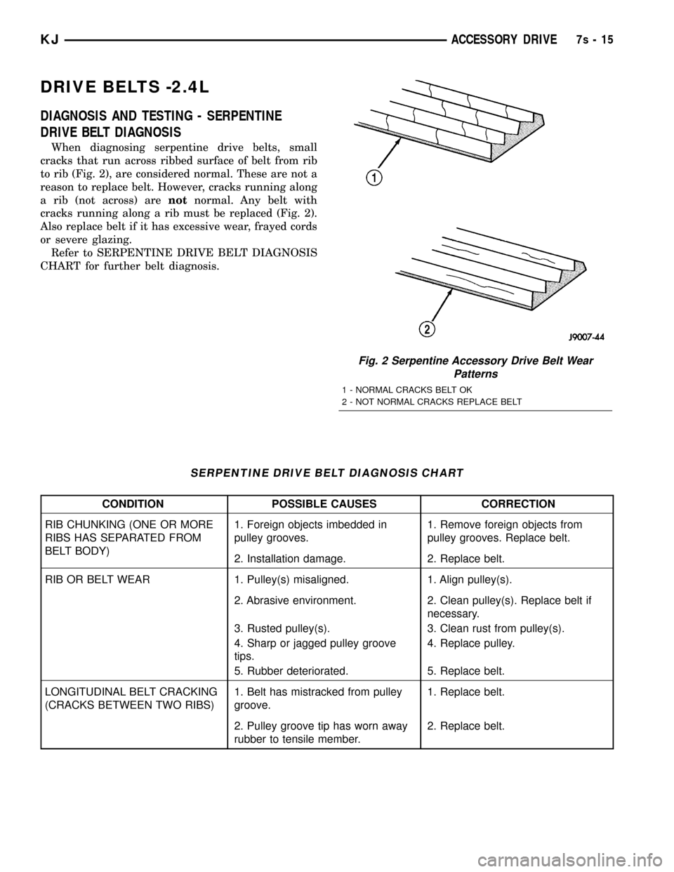
When diagnosing serpentine drive belts, small
cracks that run across ribbed surface of belt from rib
to rib (Fig. 2), are considered normal. These are not a
reason to replace belt. However, cracks running along
a rib (not across) arenotnormal. Any belt with
cracks running along a rib must be replaced (Fig. 2).
Also replace belt if it has excessive wear, frayed cords
or severe glazing.
Refer to SERPENTINE DRIVE BELT DIAGNOSIS
CHART for further belt diagnosis.
SERPENTINE DRIVE BELT DIAGNOSIS CHART
CONDITION POSSIBLE CAUSES CORRECTION
RIB CHUNKING (ONE OR MORE
RIBS HAS SEPARATED FROM
BELT BODY)1. Foreign objects imbedded in
pulley grooves.1. Remove foreign objects from
pulley grooves. Replace belt.
2. Installation damage. 2. Replace belt.
RIB OR BELT WEAR 1. Pulley(s) misaligned. 1. Align pulley(s).
2. Abrasive environment. 2. Clean pulley(s). Replace belt if
necessary.
3. Rusted pulley(s). 3. Clean rust from pulley(s).
4. Sharp or jagged pulley groove
tips.4. Replace pulley.
5. Rubber deteriorated. 5. Replace belt.
LONGITUDINAL BELT CRACKING
(CRACKS BETWEEN TWO RIBS)1. Belt has mistracked from pulley
groove.1. Replace belt.
2. Pulley groove tip has worn away
rubber to tensile member.2. Replace belt.
Fig. 2 Serpentine Accessory Drive Belt Wear
Patterns
1 - NORMAL CRACKS BELT OK
2 - NOT NORMAL CRACKS REPLACE BELT
KJACCESSORY DRIVE7s-15
Page 264 of 1803

INSTALLATION - 2.4L ENGINE
NOTE: The belt routing schematics are published
from the latest information available at the time of
publication. If anything differs between these sche-
matics and the Belt Routing Label, use the sche-
matics on Belt Routing Label. This label is located
in the engine compartment.
Belt tension is not adjustable. Belt adjustment is
maintained by an automatic ( spring load ) belt ten-
sioner.
(1) Check condition of all pulleys.
CAUTION: When installing the serpentine accessory
drive belt, the belt MUST be routed correctly. If not,
the engine may overheat due to the water pump
rotating in the wrong direction.
(2) Install new belt (Fig. 3) or (Fig. 4). Route the
belt around all pulleys except the idler pulley. Rotate
the tensioner arm until it contacts its stop position.
Route the belt around the idler and slowly let the
tensioner rotate into the belt. Make sure the belt is
seated onto all pulleys.
(3) With the drive belt installed, inspect the belt
wear indicator. On 2.4L Engines the gap between the
tang and the housing stop ( measurement A ) must
not exceed 24 mm (.94 inches).
Fig. 3 BELT ROUTING 2.4L WITH A/C
1 - IDLER PULLEY
2 - GENERATOR PULLEY
3 - IDLER PULLEY
4 - POWER STEERING PUMP PULLEY
5 -CRANKSHAFT PULLEY
6 - TENSIONER
7 - A/C COMPRESSOR PULLEY
8 - ACCESSORY DRIVE BELT
Fig. 4 BELT ROUTING 2.4L WITHOUT A/C
1 - IDLER PULLEY
2 - GENERATOR PULLEY
3 - IDLER PULLEY
4 - POWER STEERING PUMP PULLEY
5 -CRANKSHAFT PULLEY
6 - TENSIONER
7 - NON A/C IDLER PULLEY
8 - ACCESSORY DRIVE BELT
KJACCESSORY DRIVE7s-17
DRIVE BELTS -2.4L (Continued)