2002 JEEP LIBERTY power steering
[x] Cancel search: power steeringPage 1380 of 1803

(3) Align the engine cradle to the marks made dur-
ing removal and install the mounting and inner rail
bolts.
(4) Tighten the mounting bolts to 122 N´m (90 ft.
lbs.).
(5) Tighten the inner rail bolts to 47 N´m (35 ft.
lbs.).
(6) Tighten the engine mount through bolts to 88
N´m (65 ft. lbs.).
(7) Install the power steering rack. (Refer to 19 -
STEERING/GEAR - INSTALLATION)
(8) Install the front axle, if equipped. (Refer to 3 -
DIFFERENTIAL & DRIVELINE/FRONT AXLE -
INSTALLATION)
(9) Install the stabilizer bar. (Refer to 2 - SUS-
PENSION/FRONT/STABILIZER BAR - INSTALLA-
TION)
(10) Install the lower control arms. (Refer to 2 -
SUSPENSION/FRONT/LOWER CONTROL ARM -
INSTALLATION)
(11) Lower the vehicle and remove the engine sup-
port tool.
TRANSFER CASE SKID PLATE
REMOVAL
(1) Remove the bolts and remove the skid plate.
(Fig. 8)
INSTALLATION
(1) Install the skid plate.
(2) Install the bolts and tighten to 34 N´m (25 ft.
lbs.).
REAR CROSSMEMBER
REMOVAL
(1) Raise and support the vehicle.
(2) Support the transmission with a suitable lifting
device.
(3) Remove the transmission mount through bolt.
(4) Remove the crossmember bolts and remove the
crossmember. (Fig. 9)
INSTALLATION
(1) Install the crossmember and install the bolts.
(2) Tighten the bolts to 47 N´m (35 ft. lbs.)
(3) Install transmission mount through bolt and
tighten to 88 N´m (65 ft. lbs.).
Fig. 8 SKID PLATE
1 - SKID PLATE
2 - BOLTS
Fig. 9 CROSS MEMBER
1 - CROSSMEMBER
2 - BOLTS
KJFRAMES & BUMPERS 13 - 7
ENGINE CRADLE CROSSMEMBER (Continued)
Page 1387 of 1803

SPECIFICATIONS
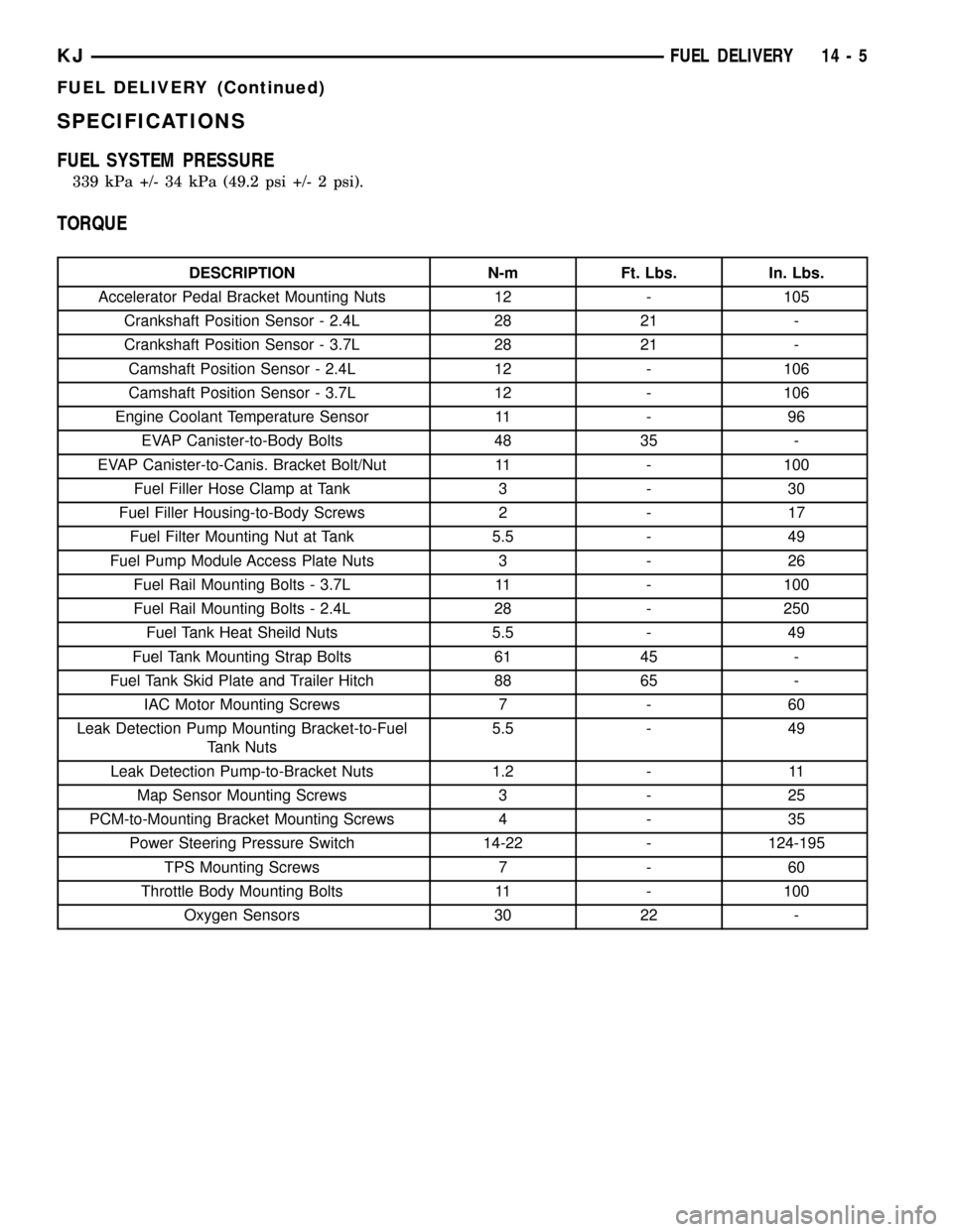
FUEL SYSTEM PRESSURE
339 kPa +/- 34 kPa (49.2 psi +/- 2 psi).
TORQUE
DESCRIPTION N-m Ft. Lbs. In. Lbs.
Accelerator Pedal Bracket Mounting Nuts 12 - 105
Crankshaft Position Sensor - 2.4L 28 21 -
Crankshaft Position Sensor - 3.7L 28 21 -
Camshaft Position Sensor - 2.4L 12 - 106
Camshaft Position Sensor - 3.7L 12 - 106
Engine Coolant Temperature Sensor 11 - 96
EVAP Canister-to-Body Bolts 48 35 -
EVAP Canister-to-Canis. Bracket Bolt/Nut 11 - 100
Fuel Filler Hose Clamp at Tank 3 - 30
Fuel Filler Housing-to-Body Screws 2 - 17
Fuel Filter Mounting Nut at Tank 5.5 - 49
Fuel Pump Module Access Plate Nuts 3 - 26
Fuel Rail Mounting Bolts - 3.7L 11 - 100
Fuel Rail Mounting Bolts - 2.4L 28 - 250
Fuel Tank Heat Sheild Nuts 5.5 - 49
Fuel Tank Mounting Strap Bolts 61 45 -
Fuel Tank Skid Plate and Trailer Hitch 88 65 -
IAC Motor Mounting Screws 7 - 60
Leak Detection Pump Mounting Bracket-to-Fuel
Tank Nuts5.5 - 49
Leak Detection Pump-to-Bracket Nuts 1.2 - 11
Map Sensor Mounting Screws 3 - 25
PCM-to-Mounting Bracket Mounting Screws 4 - 35
Power Steering Pressure Switch 14-22 - 124-195
TPS Mounting Screws 7 - 60
Throttle Body Mounting Bolts 11 - 100
Oxygen Sensors 30 22 -
KJFUEL DELIVERY 14 - 5
FUEL DELIVERY (Continued)
Page 1417 of 1803

IDLE AIR CONTROL MOTOR
DESCRIPTION
The IAC stepper motor is mounted to the throttle
body, and regulates the amount of air bypassing the
control of the throttle plate. As engine loads and
ambient temperatures change, engine rpm changes.
A pintle on the IAC stepper motor protrudes into a
passage in the throttle body, controlling air flow
through the passage. The IAC is controlled by the
Powertrain Control Module (PCM) to maintain the
target engine idle speed.
OPERATION
At idle, engine speed can be increased by retract-
ing the IAC motor pintle and allowing more air to
pass through the port, or it can be decreased by
restricting the passage with the pintle and diminish-
ing the amount of air bypassing the throttle plate.
The IAC is called a stepper motor because it is
moved (rotated) in steps, or increments. Opening the
IAC opens an air passage around the throttle blade
which increases RPM.
The PCM uses the IAC motor to control idle speed
(along with timing) and to reach a desired MAP dur-
ing decel (keep engine from stalling).
The IAC motor has 4 wires with 4 circuits. Two of
the wires are for 12 volts and ground to supply elec-
trical current to the motor windings to operate the
stepper motor in one direction. The other 2 wires are
also for 12 volts and ground to supply electrical cur-
rent to operate the stepper motor in the opposite
direction.
To make the IAC go in the opposite direction, the
PCM just reverses polarity on both windings. If only
1 wire is open, the IAC can only be moved 1 step
(increment) in either direction. To keep the IAC
motor in position when no movement is needed, the
PCM will energize both windings at the same time.
This locks the IAC motor in place.
In the IAC motor system, the PCM will count
every step that the motor is moved. This allows the
PCM to determine the motor pintle position. If the
memory is cleared, the PCM no longer knows the
position of the pintle. So at the first key ON, the
PCM drives the IAC motor closed, regardless of
where it was before. This zeros the counter. Fromthis point the PCM will back out the IAC motor and
keep track of its position again.
When engine rpm is above idle speed, the IAC is
used for the following:
²Off-idle dashpot (throttle blade will close quickly
but idle speed will not stop quickly)
²Deceleration air flow control
²A/C compressor load control (also opens the pas-
sage slightly before the compressor is engaged so
that the engine rpm does not dip down when the
compressor engages)
²Power steering load control
The PCM can control polarity of the circuit to con-
trol direction of the stepper motor.
IAC Stepper Motor Program:The PCM is also
equipped with a memory program that records the
number of steps the IAC stepper motor most recently
advanced to during a certain set of parameters. For
example: The PCM was attempting to maintain a
1000 rpm target during a cold start-up cycle. The last
recorded number of steps for that may have been
125. That value would be recorded in the memory
cell so that the next time the PCM recognizes the
identical conditions, the PCM recalls that 125 steps
were required to maintain the target. This program
allows for greater customer satisfaction due to
greater control of engine idle.
Another function of the memory program, which
occurs when the power steering switch (if equipped),
or the A/C request circuit, requires that the IAC step-
per motor control engine rpm, is the recording of the
last targeted steps into the memory cell. The PCM
can anticipate A/C compressor loads. This is accom-
plished by delaying compressor operation for approx-
imately 0.5 seconds until the PCM moves the IAC
stepper motor to the recorded steps that were loaded
into the memory cell. Using this program helps elim-
inate idle-quality changes as loads change. Finally,
the PCM incorporates a9No-Load9engine speed lim-
iter of approximately 1800 - 2000 rpm, when it rec-
ognizes that the TPS is indicating an idle signal and
IAC motor cannot maintain engine idle.
A (factory adjusted) set screw is used to mechani-
cally limit the position of the throttle body throttle
plate.Never attempt to adjust the engine idle
speed using this screw.All idle speed functions are
controlled by the IAC motor through the PCM.
KJFUEL INJECTION 14 - 35
Page 1431 of 1803

STEERING
TABLE OF CONTENTS
page page
STEERING
DESCRIPTION..........................1
OPERATION............................1
DIAGNOSIS AND TESTING
DIAGNOSIS AND TESTING - POWER
STEERING SYSTEM....................1DIAGNOSIS AND TESTING - POWER
STEERING FLOW AND PRESSURE........3
COLUMN...............................5
GEAR.................................13
LINKAGE..............................16
PUMP.................................17
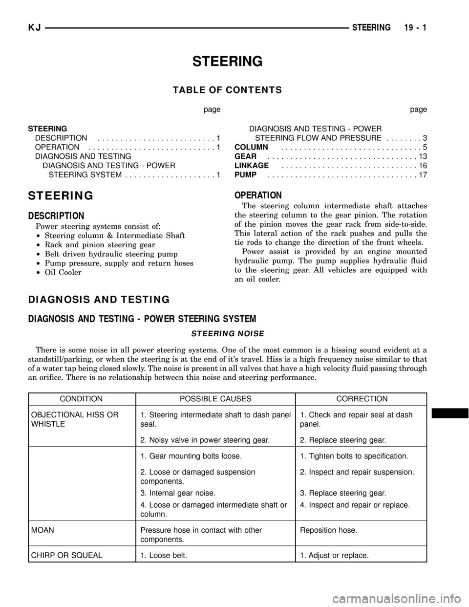
STEERING
DESCRIPTION
Power steering systems consist of:
²Steering column & Intermediate Shaft
²Rack and pinion steering gear
²Belt driven hydraulic steering pump
²Pump pressure, supply and return hoses
²Oil Cooler
OPERATION
The steering column intermediate shaft attaches
the steering column to the gear pinion. The rotation
of the pinion moves the gear rack from side-to-side.
This lateral action of the rack pushes and pulls the
tie rods to change the direction of the front wheels.
Power assist is provided by an engine mounted
hydraulic pump. The pump supplies hydraulic fluid
to the steering gear. All vehicles are equipped with
an oil cooler.
DIAGNOSIS AND TESTING
DIAGNOSIS AND TESTING - POWER STEERING SYSTEM
STEERING NOISE
There is some noise in all power steering systems. One of the most common is a hissing sound evident at a
standstill/parking, or when the steering is at the end of it's travel. Hiss is a high frequency noise similar to that
of a water tap being closed slowly. The noise is present in all valves that have a high velocity fluid passing through
an orifice. There is no relationship between this noise and steering performance.
CONDITION POSSIBLE CAUSES CORRECTION
OBJECTIONAL HISS OR
WHISTLE1. Steering intermediate shaft to dash panel
seal.1. Check and repair seal at dash
panel.
2. Noisy valve in power steering gear. 2. Replace steering gear.
1. Gear mounting bolts loose. 1. Tighten bolts to specification.
2. Loose or damaged suspension
components.2. Inspect and repair suspension.
3. Internal gear noise. 3. Replace steering gear.
4. Loose or damaged intermediate shaft or
column.4. Inspect and repair or replace.
MOAN Pressure hose in contact with other
components.Reposition hose.
CHIRP OR SQUEAL 1. Loose belt. 1. Adjust or replace.
KJSTEERING 19 - 1
Page 1433 of 1803

LOOSE STEERING AND VEHICLE LEAD
CONDITION POSSIBLE CAUSE CORRECTION
EXCESSIVE PLAY IN STEERING
WHEEL1. Worn or loose suspension or
steering components.1. Inspect and repair as necessary.
2. Worn or loose wheel bearings. 2. Inspect and replace bearings.
3. Steering gear mounting. 3. Tighten / replace gear mounting
bolts/ isolators to specification.
4. Gear out of adjustment. 4. Replace gear.
5. Worn or loose steering
intermediate shaft.5. Inspect and replace as
necessary.
VEHICLE PULLS, DRIFTS OR
LEADS TO ONE SIDE.1. Tire Pressure. 1. Adjust tire pressure.
2. Radial tire lead. 2. Rotate tires.
3. Brakes dragging. 3. Repair as necessary.
4. Wheel alignment. 4. Align front end.
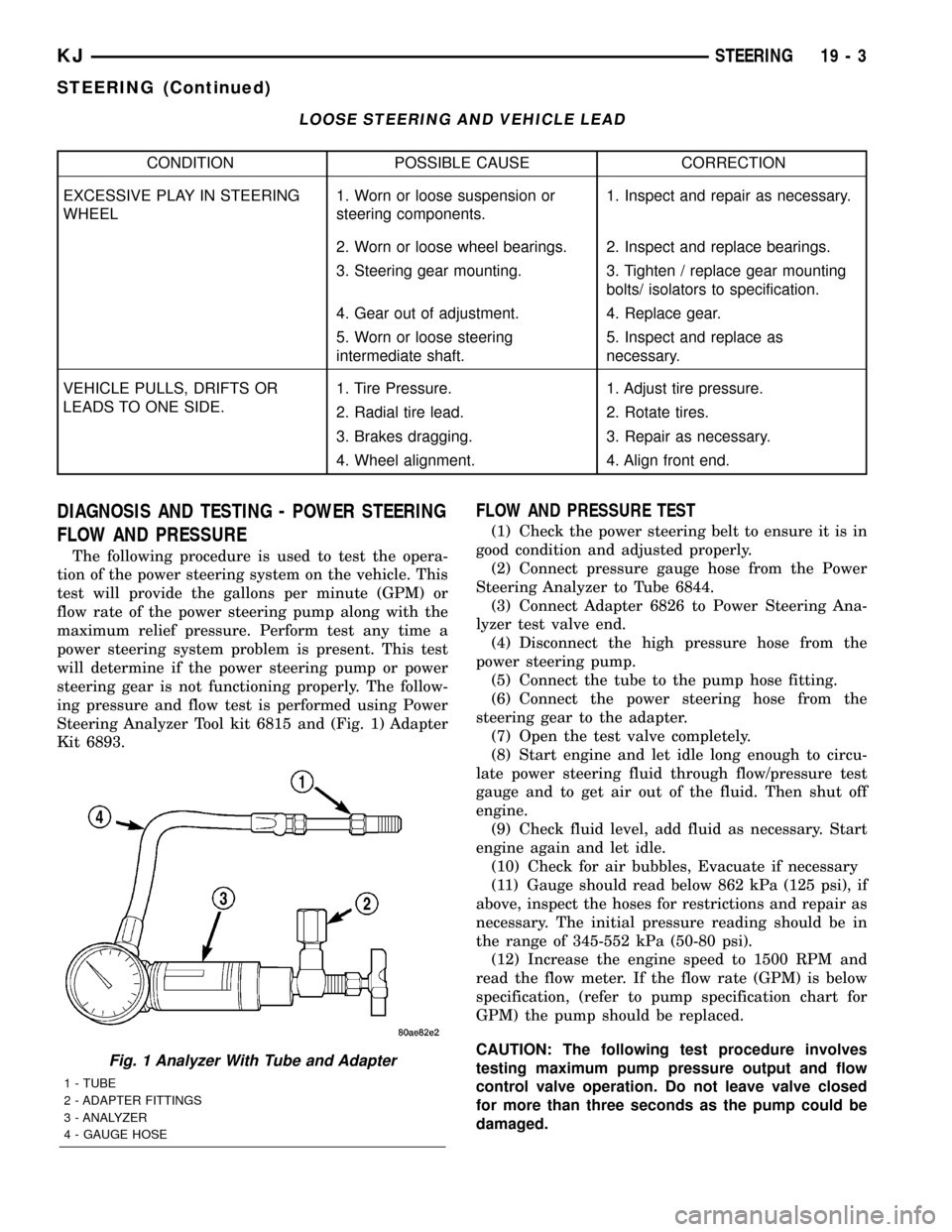
DIAGNOSIS AND TESTING - POWER STEERING
FLOW AND PRESSURE
The following procedure is used to test the opera-
tion of the power steering system on the vehicle. This
test will provide the gallons per minute (GPM) or
flow rate of the power steering pump along with the
maximum relief pressure. Perform test any time a
power steering system problem is present. This test
will determine if the power steering pump or power
steering gear is not functioning properly. The follow-
ing pressure and flow test is performed using Power
Steering Analyzer Tool kit 6815 and (Fig. 1) Adapter
Kit 6893.
FLOW AND PRESSURE TEST
(1) Check the power steering belt to ensure it is in
good condition and adjusted properly.
(2) Connect pressure gauge hose from the Power
Steering Analyzer to Tube 6844.
(3) Connect Adapter 6826 to Power Steering Ana-
lyzer test valve end.
(4) Disconnect the high pressure hose from the
power steering pump.
(5) Connect the tube to the pump hose fitting.
(6) Connect the power steering hose from the
steering gear to the adapter.
(7) Open the test valve completely.
(8) Start engine and let idle long enough to circu-
late power steering fluid through flow/pressure test
gauge and to get air out of the fluid. Then shut off
engine.
(9) Check fluid level, add fluid as necessary. Start
engine again and let idle.
(10) Check for air bubbles, Evacuate if necessary
(11) Gauge should read below 862 kPa (125 psi), if
above, inspect the hoses for restrictions and repair as
necessary. The initial pressure reading should be in
the range of 345-552 kPa (50-80 psi).
(12) Increase the engine speed to 1500 RPM and
read the flow meter. If the flow rate (GPM) is below
specification, (refer to pump specification chart for
GPM) the pump should be replaced.
CAUTION: The following test procedure involves
testing maximum pump pressure output and flow
control valve operation. Do not leave valve closed
for more than three seconds as the pump could be
damaged.
Fig. 1 Analyzer With Tube and Adapter
1 - TUBE
2 - ADAPTER FITTINGS
3 - ANALYZER
4 - GAUGE HOSE
KJSTEERING 19 - 3
STEERING (Continued)
Page 1443 of 1803

GEAR
TABLE OF CONTENTS
page page
GEAR
DESCRIPTION.........................13
OPERATION...........................13
REMOVAL
REMOVAL - 4WD......................13
REMOVAL - 2WD......................14
INSTALLATION
INSTALLATION - 4WD..................14INSTALLATION - 2WD..................14
SPECIFICATIONS
TORQUE CHART......................15
SPECIAL TOOLS
OUTER TIE ROD END REMOVAL TOOL....15
GEAR
DESCRIPTION
A rack and pinion steering gear (Fig. 1) is made up
of two main components, the pinon shaft and the
rack. The gear cannot be adjusted or internally ser-
viced. If a malfunction or a fluid leak occurs, the gear
must be replaced as an assembly.
OPERATION
The steering column intermediate shaft is attached
to the gear pinion. The rotation of the pinion moves
the gear rack from side-to-side. This lateral action of
the rack pushes and pulls the tie rods, which are
connected to the steering knuckles to change the
direction of the front wheels.
REMOVAL
REMOVAL - 4WD
(1) Siphon the power steering fluid from the power
steering reservoir.
(2) Lock the steering wheel to prevent spinning of
the clockspring.
(3) Raise and support the vehicle.
(4) Remove the skid plate from under the front
end to gain access to the gear (Refer to 13 - FRAME
& BUMPERS/FRAME/FRONT SKID PLATE -
REMOVAL).
(5) Remove the front tire and wheel assemblies.
NOTE: Mark the alignment adjusting cams for eas-
ier installation.
(6) Remove the lower control arms. (Refer to 2 -
SUSPENSION/FRONT/LOWER CONTROL ARM -
REMOVAL).
(7) Remove the front axle. (Refer to 3 - DIFFER-
ENTIAL & DRIVELINE/FRONT AXLE - REMOV-
AL).
(8) Remove the tie rod end nuts.
(9) Separate tie rod ends from the knuckles with
Puller C-3894-A.
(10) Remove the intermediate shaft lower coupler
bolt and slide the coupler off the gear (Fig. 2).
(11) Remove power steering pressure hose bracket
(Fig. 3).
(12) Remove the power steering lines from the
gear (Fig. 2).
(13) Remove the mounting bolts from the gear to
the front cradle (Fig. 3).
(14) Remove the steering gear from the vehicle.
Fig. 1 Rack & Pinion Steering Gear
1 - TIE ROD - INNER
2 - TIE ROD - INNER
3 - TIE ROD END - OUTER LH
4 - BOOTS
5 - TIE ROD END - OUTER RH
KJGEAR 19 - 13
Page 1444 of 1803

REMOVAL - 2WD
(1) Siphon the power steering fluid from the power
steering reservoir.
(2) Lock the steering wheel to prevent spinning of
the clockspring.
(3) Raise and support the vehicle.
(4) Remove the skid plate from under the front
end to gain access to the gear(Refer to 13 - FRAME
& BUMPERS/FRAME/FRONT SKID PLATE -
REMOVAL).
(5) Remove the tire and wheel assembly.
NOTE: Mark the alignment adjusting cams and tie
rod end jam nuts on the steering gear for easier
installation.
(6) Remove the tie rod end nuts.
(7) Separate tie rod ends from the knuckles with
Puller C-3894-A.
(8) Remove the lower intermediate shaft coupler
bolt and slide the coupler off the gear (Fig. 2).(9) Remove power steering pressure hose bracket
(Fig. 3).
(10) Remove the power steering lines from the
gear (Fig. 2).
(11) Remove the mounting bolts from the gear to
the front cradle (Fig. 3).
(12) Remove the steering gear from the vehicle.
INSTALLATION
INSTALLATION - 4WD
(1) Transfer the tie rod ends to the new steering
gear (if needed).
(2) Install the steering gear to the vehicle.
(3) Install the gear mounting bolts to the front cra-
dle. (Fig. 3). Tighten the gear mounting bolts to 162
N´m (120 ft.lbs.)
(4) Install the power steering lines to the gear
(Fig. 2).
(5) Install the power steering pressure hose
bracket (Fig. 3).
(6) Install the lower coupler bolt and slide the cou-
pler on to the gear (Fig. 2).
(7) Install the tie rod end to the knuckle and
tighten the nuts.
(8) Install the front axle. (Refer to 3 - DIFFEREN-
TIAL & DRIVELINE/FRONT AXLE - INSTALLA-
TION).
(9) Install the lower control arms. (Refer to 2 -
SUSPENSION/FRONT/LOWER CONTROL ARM -
INSTALLATION).
(10) Install the tire and wheel assembly. (Refer to
22 - TIRES/WHEELS/WHEELS - STANDARD PRO-
CEDURE).
(11) Install the skid plate (Refer to 13 - FRAME &
BUMPERS/FRAME/FRONT SKID PLATE - INSTAL-
LATION).
(12) Lower the vehicle.
(13) Unlock the steering wheel.
(14) Fill the power steering fluid (Refer to 19 -
STEERING/PUMP - STANDARD PROCEDURE).
(15) Reset the toe and center the steering wheel
(Refer to 2 - SUSPENSION/WHEEL ALIGNMENT -
STANDARD PROCEDURE).
INSTALLATION - 2WD
(1) Transfer the outer tie rod ends to the new
steering gear (if needed).
(2) Install the steering gear to the vehicle.
(3) Install the gear mounting bolts to the front cra-
dle. (Fig. 3). Tighten the gear mounting bolts to 162
N´m (120 ft.lbs.)
(4) Install the power steering lines to the gear
(Fig. 2).
Fig. 2 COUPLER BOLT
Fig. 3 RACK & PINION
19 - 14 GEARKJ
GEAR (Continued)
Page 1445 of 1803

(5) Install the power steering pressure hose
bracket (Fig. 3).
(6) Install the lower coupler bolt and slide the cou-
pler on to the gear (Fig. 2).
(7) Install the tie rod end to the knuckle and
tighten the nuts.
(8) Install the tire and wheel assembly. (Refer to
22 - TIRES/WHEELS/WHEELS - STANDARD PRO-
CEDURE).
(9) Install the skid plate(Refer to 13 - FRAME &
BUMPERS/FRAME/FRONT SKID PLATE - INSTAL-
LATION).(10) Lower the vehicle.
(11) Unlock the steering wheel.
(12) Fill the power steering fluid (Refer to 19 -
STEERING/PUMP - STANDARD PROCEDURE).
(13) Reset the toe and center the steering wheel
(Refer to 2 - SUSPENSION/WHEEL ALIGNMENT -
STANDARD PROCEDURE).
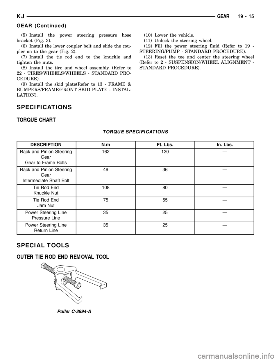
SPECIFICATIONS
TORQUE CHART
TORQUE SPECIFICATIONS
DESCRIPTION N´m Ft. Lbs. In. Lbs.
Rack and Pinion Steering
Gear
Gear to Frame Bolts162 120 Ð
Rack and Pinion Steering
Gear
Intermediate Shaft Bolt49 36 Ð
Tie Rod End
Knuckle Nut108 80 Ð
Tie Rod End
Jam Nut75 55 Ð
Power Steering Line
Pressure Line35 25 Ð
Power Steering Line
Return Line35 25 Ð
SPECIAL TOOLS
OUTER TIE ROD END REMOVAL TOOL
Puller C-3894-A
KJGEAR 19 - 15
GEAR (Continued)