2002 JEEP LIBERTY fuel pump
[x] Cancel search: fuel pumpPage 1408 of 1803
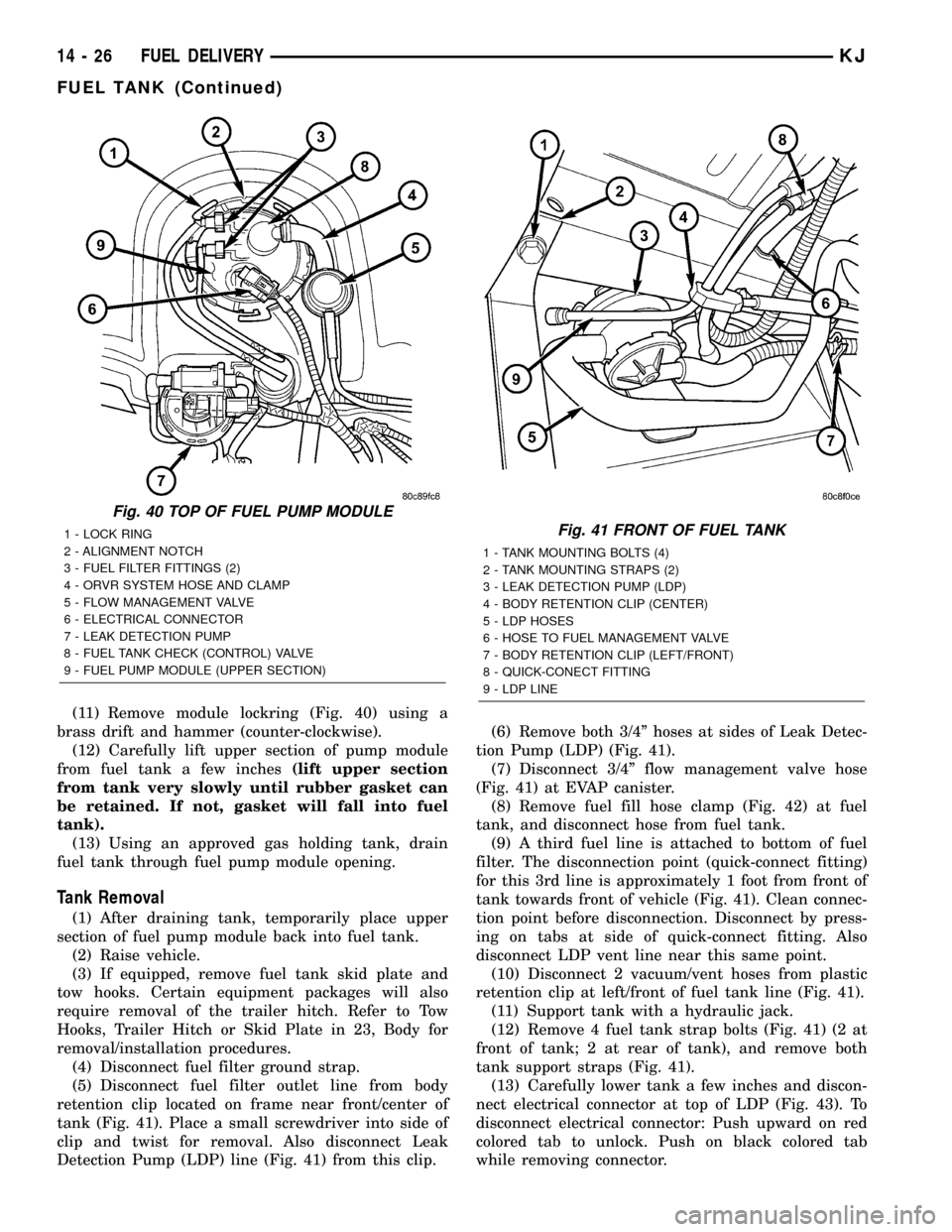
(11) Remove module lockring (Fig. 40) using a
brass drift and hammer (counter-clockwise).
(12) Carefully lift upper section of pump module
from fuel tank a few inches(lift upper section
from tank very slowly until rubber gasket can
be retained. If not, gasket will fall into fuel
tank).
(13) Using an approved gas holding tank, drain
fuel tank through fuel pump module opening.
Tank Removal
(1) After draining tank, temporarily place upper
section of fuel pump module back into fuel tank.
(2) Raise vehicle.
(3) If equipped, remove fuel tank skid plate and
tow hooks. Certain equipment packages will also
require removal of the trailer hitch. Refer to Tow
Hooks, Trailer Hitch or Skid Plate in 23, Body for
removal/installation procedures.
(4) Disconnect fuel filter ground strap.
(5) Disconnect fuel filter outlet line from body
retention clip located on frame near front/center of
tank (Fig. 41). Place a small screwdriver into side of
clip and twist for removal. Also disconnect Leak
Detection Pump (LDP) line (Fig. 41) from this clip.(6) Remove both 3/4º hoses at sides of Leak Detec-
tion Pump (LDP) (Fig. 41).
(7) Disconnect 3/4º flow management valve hose
(Fig. 41) at EVAP canister.
(8) Remove fuel fill hose clamp (Fig. 42) at fuel
tank, and disconnect hose from fuel tank.
(9) A third fuel line is attached to bottom of fuel
filter. The disconnection point (quick-connect fitting)
for this 3rd line is approximately 1 foot from front of
tank towards front of vehicle (Fig. 41). Clean connec-
tion point before disconnection. Disconnect by press-
ing on tabs at side of quick-connect fitting. Also
disconnect LDP vent line near this same point.
(10) Disconnect 2 vacuum/vent hoses from plastic
retention clip at left/front of fuel tank line (Fig. 41).
(11) Support tank with a hydraulic jack.
(12) Remove 4 fuel tank strap bolts (Fig. 41) (2 at
front of tank; 2 at rear of tank), and remove both
tank support straps (Fig. 41).
(13) Carefully lower tank a few inches and discon-
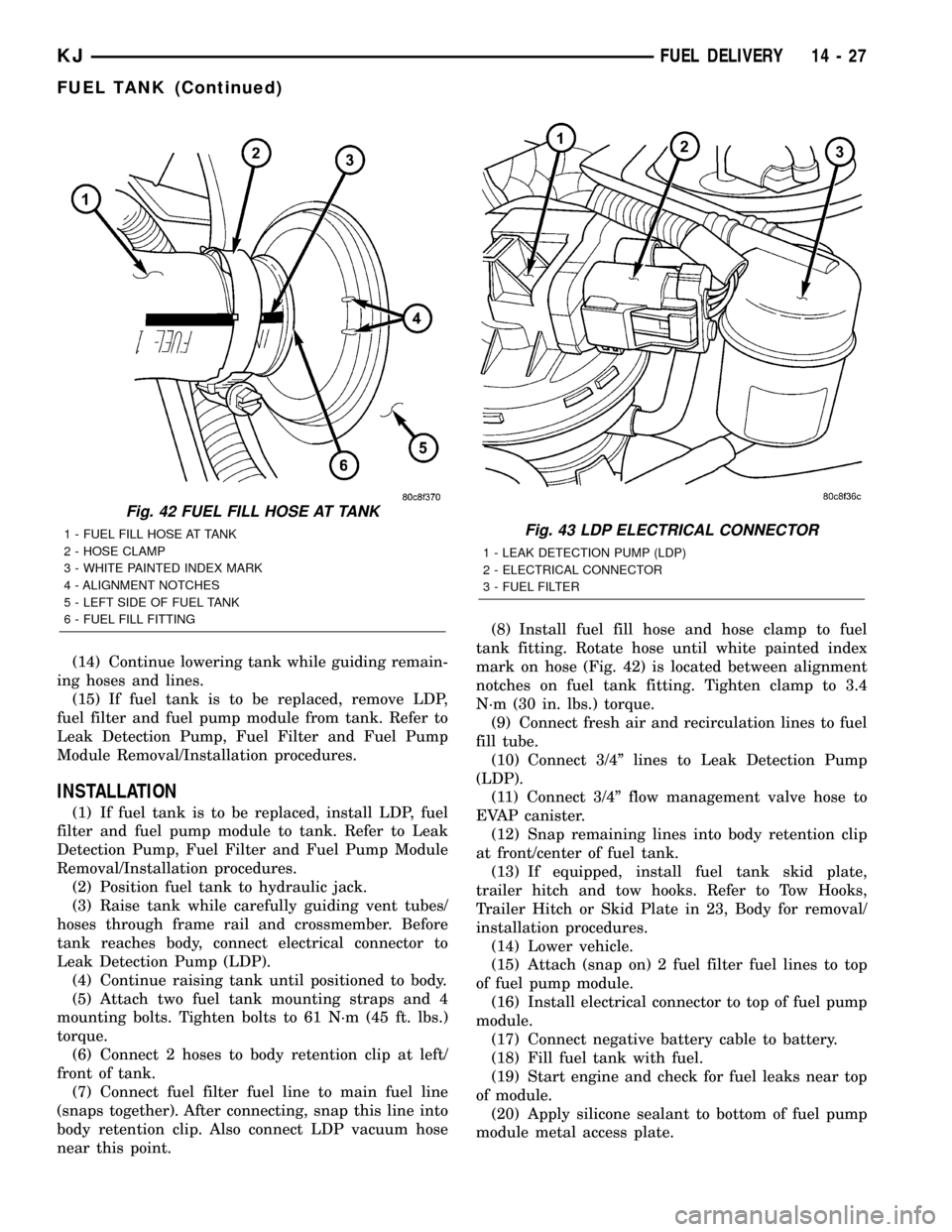
nect electrical connector at top of LDP (Fig. 43). To
disconnect electrical connector: Push upward on red
colored tab to unlock. Push on black colored tab
while removing connector.
Fig. 40 TOP OF FUEL PUMP MODULE
1 - LOCK RING
2 - ALIGNMENT NOTCH
3 - FUEL FILTER FITTINGS (2)
4 - ORVR SYSTEM HOSE AND CLAMP
5 - FLOW MANAGEMENT VALVE
6 - ELECTRICAL CONNECTOR
7 - LEAK DETECTION PUMP
8 - FUEL TANK CHECK (CONTROL) VALVE
9 - FUEL PUMP MODULE (UPPER SECTION)Fig. 41 FRONT OF FUEL TANK
1 - TANK MOUNTING BOLTS (4)
2 - TANK MOUNTING STRAPS (2)
3 - LEAK DETECTION PUMP (LDP)
4 - BODY RETENTION CLIP (CENTER)
5 - LDP HOSES
6 - HOSE TO FUEL MANAGEMENT VALVE
7 - BODY RETENTION CLIP (LEFT/FRONT)
8 - QUICK-CONECT FITTING
9 - LDP LINE
14 - 26 FUEL DELIVERYKJ
FUEL TANK (Continued)
Page 1409 of 1803
(14) Continue lowering tank while guiding remain-
ing hoses and lines.
(15) If fuel tank is to be replaced, remove LDP,
fuel filter and fuel pump module from tank. Refer to
Leak Detection Pump, Fuel Filter and Fuel Pump
Module Removal/Installation procedures.
INSTALLATION
(1) If fuel tank is to be replaced, install LDP, fuel
filter and fuel pump module to tank. Refer to Leak
Detection Pump, Fuel Filter and Fuel Pump Module
Removal/Installation procedures.
(2) Position fuel tank to hydraulic jack.
(3) Raise tank while carefully guiding vent tubes/
hoses through frame rail and crossmember. Before
tank reaches body, connect electrical connector to
Leak Detection Pump (LDP).
(4) Continue raising tank until positioned to body.
(5) Attach two fuel tank mounting straps and 4
mounting bolts. Tighten bolts to 61 N´m (45 ft. lbs.)
torque.
(6) Connect 2 hoses to body retention clip at left/
front of tank.
(7) Connect fuel filter fuel line to main fuel line
(snaps together). After connecting, snap this line into
body retention clip. Also connect LDP vacuum hose
near this point.(8) Install fuel fill hose and hose clamp to fuel
tank fitting. Rotate hose until white painted index
mark on hose (Fig. 42) is located between alignment
notches on fuel tank fitting. Tighten clamp to 3.4
N´m (30 in. lbs.) torque.
(9) Connect fresh air and recirculation lines to fuel
fill tube.
(10) Connect 3/4º lines to Leak Detection Pump
(LDP).
(11) Connect 3/4º flow management valve hose to
EVAP canister.
(12) Snap remaining lines into body retention clip
at front/center of fuel tank.
(13) If equipped, install fuel tank skid plate,
trailer hitch and tow hooks. Refer to Tow Hooks,
Trailer Hitch or Skid Plate in 23, Body for removal/
installation procedures.
(14) Lower vehicle.
(15) Attach (snap on) 2 fuel filter fuel lines to top
of fuel pump module.
(16) Install electrical connector to top of fuel pump
module.
(17) Connect negative battery cable to battery.
(18) Fill fuel tank with fuel.
(19) Start engine and check for fuel leaks near top
of module.
(20) Apply silicone sealant to bottom of fuel pump
module metal access plate.
Fig. 42 FUEL FILL HOSE AT TANK
1 - FUEL FILL HOSE AT TANK
2 - HOSE CLAMP
3 - WHITE PAINTED INDEX MARK
4 - ALIGNMENT NOTCHES
5 - LEFT SIDE OF FUEL TANK
6 - FUEL FILL FITTINGFig. 43 LDP ELECTRICAL CONNECTOR
1 - LEAK DETECTION PUMP (LDP)
2 - ELECTRICAL CONNECTOR
3 - FUEL FILTER
KJFUEL DELIVERY 14 - 27
FUEL TANK (Continued)
Page 1410 of 1803
(21) Install fuel pump module metal access plate
and 4 nuts. Tighten nuts to 3 N´m (26 in. lbs.)
torque.
(22) Position carpet and install 2 new cargo clamp
rivets into each cargo holdown clamp.
FUEL TANK CHECK VALVE
DESCRIPTION
The fuel tank is equipped with a check valve. The
valve (also referred to as a control valve) is located in
the top section of the fuel pump module assembly
(Fig. 1).
OPERATION
The fuel tank check valve (also referred to as
either a control valve, one-way check valve or float
valve) will prevent fuel flow through the fuel tank
vent in the event of an accidental vehicle rollover. It
is also used as a part of the ORVR system. The
EVAP canister and ORVR system draw fuel vapors
from the fuel tank through this valve. Refer to ORVR
in Emissions for additional information.
The valve may be serviced by replacing the upper
section of the fuel pump module assembly.
REMOVAL
The fuel tank check (control) valve is attached into
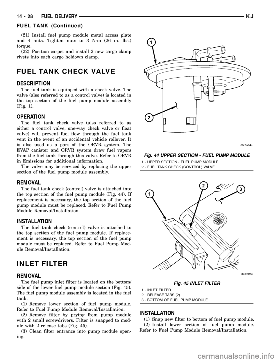
the top section of the fuel pump module (Fig. 44). If
replacement is necessary, the top section of the fuel
pump module must be replaced. Refer to Fuel Pump
Module Removal/Installation.
INSTALLATION
The fuel tank check (control) valve is attached to
the top section of the fuel pump module. If replace-
ment is necessary, the top section of the fuel pump
module must be replaced. Refer to Fuel Pump Mod-
ule Removal/Installation.
INLET FILTER
REMOVAL
The fuel pump inlet filter is located on the bottom/
side of the lower fuel pump module section (Fig. 45).
The fuel pump module assembly is located in the fuel
tank.
(1) Remove lower section of fuel pump module.
Refer to Fuel Pump Module Removal/Installation.
(2) Remove filter by prying from pump module
with 2 small screwdrivers. Filter is snapped to mod-
ule with 2 release tabs (Fig. 45).
(3) Clean filter entrance into pump module open-
ing.
INSTALLATION
(1) Snap new filter to bottom of fuel pump module.
(2) Install lower section of fuel pump module.
Refer to Fuel Pump Module Removal/Installation.
Fig. 44 UPPER SECTION - FUEL PUMP MODULE
1 - UPPER SECTION - FUEL PUMP MODULE
2 - FUEL TANK CHECK (CONTROL) VALVE
Fig. 45 INLET FILTER
1 - INLET FILTER
2 - RELEASE TABS (2)
3 - BOTTOM OF FUEL PUMP MODULE
14 - 28 FUEL DELIVERYKJ
FUEL TANK (Continued)
Page 1411 of 1803

FUEL INJECTION
TABLE OF CONTENTS
page page
FUEL INJECTION
DESCRIPTION.........................29
ACCELERATOR PEDAL
REMOVAL.............................29
INSTALLATION.........................30
CRANKSHAFT POSITION SENSOR
DESCRIPTION.........................30
OPERATION...........................31
REMOVAL.............................31
INSTALLATION.........................32
FUEL INJECTOR
DESCRIPTION.........................33
OPERATION
OPERATION - FUEL INJECTOR..........33
OPERATION - PCM OUTPUT............33
DIAGNOSIS AND TESTING - FUEL INJECTOR . 33
REMOVAL.............................34
INSTALLATION.........................34
FUEL PUMP RELAY
DESCRIPTION.........................34
OPERATION...........................34
DIAGNOSIS AND TESTING - FUEL PUMP
RELAY..............................34
REMOVAL.............................34
INSTALLATION.........................34
IDLE AIR CONTROL MOTOR
DESCRIPTION.........................35
OPERATION...........................35
REMOVAL.............................36INSTALLATION.........................36
INTAKE AIR TEMPERATURE SENSOR
DESCRIPTION.........................36
OPERATION...........................36
REMOVAL.............................37
INSTALLATION.........................38
MAP SENSOR
DESCRIPTION.........................38
OPERATION...........................38
REMOVAL.............................39
INSTALLATION.........................40
OXYGEN SENSOR
DESCRIPTION.........................40
OPERATION...........................40
REMOVAL.............................41
INSTALLATION.........................43
THROTTLE BODY
DESCRIPTION.........................43
OPERATION...........................43
REMOVAL.............................43
INSTALLATION.........................44
THROTTLE CONTROL CABLE
REMOVAL.............................45
INSTALLATION.........................46
THROTTLE POSITION SENSOR
DESCRIPTION.........................47
OPERATION...........................47
REMOVAL.............................47
INSTALLATION.........................48
FUEL INJECTION
DESCRIPTION
The Powertrain Control Module (PCM) operates
the fuel injection system. Refer to Powertrain Control
Module in Electronic Control Modules for informa-
tion.
ACCELERATOR PEDAL
REMOVAL
The accelerator pedal is serviced as a complete
assembly including the bracket.The accelerator pedal is connected to the upper
part of the accelerator pedal arm by a plastic
retainer (clip) (Fig. 1). This plastic retainer snaps
into the top of the accelerator pedal arm.
(1) From inside the vehicle, hold up accelerator
pedal. Remove plastic cable retainer (clip) and throt-
tle cable core wire from upper end of accelerator
pedal arm (Fig. 1). Plastic cable retainer (clip) snaps
into pedal arm.
(2) Remove 2 accelerator pedal mounting bracket
nuts. Remove accelerator pedal assembly.
KJFUEL INJECTION 14 - 29
Page 1416 of 1803
REMOVAL
(1) Remove fuel rail. Refer to Fuel Injector Rail
Removal.
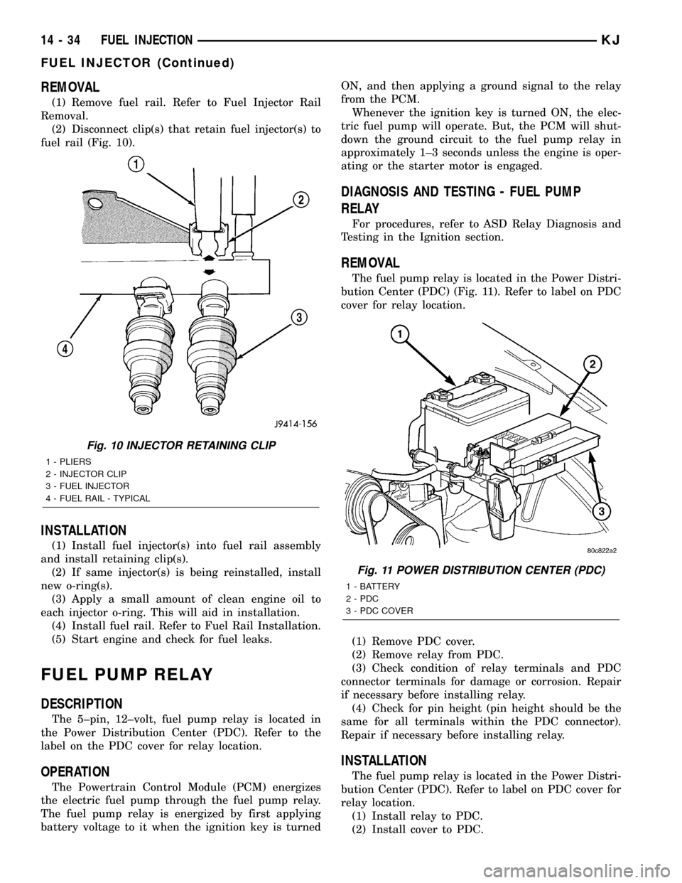
(2) Disconnect clip(s) that retain fuel injector(s) to
fuel rail (Fig. 10).
INSTALLATION
(1) Install fuel injector(s) into fuel rail assembly
and install retaining clip(s).
(2) If same injector(s) is being reinstalled, install
new o-ring(s).
(3) Apply a small amount of clean engine oil to
each injector o-ring. This will aid in installation.
(4) Install fuel rail. Refer to Fuel Rail Installation.
(5) Start engine and check for fuel leaks.
FUEL PUMP RELAY
DESCRIPTION
The 5±pin, 12±volt, fuel pump relay is located in
the Power Distribution Center (PDC). Refer to the
label on the PDC cover for relay location.
OPERATION
The Powertrain Control Module (PCM) energizes
the electric fuel pump through the fuel pump relay.
The fuel pump relay is energized by first applying
battery voltage to it when the ignition key is turnedON, and then applying a ground signal to the relay
from the PCM.
Whenever the ignition key is turned ON, the elec-
tric fuel pump will operate. But, the PCM will shut-
down the ground circuit to the fuel pump relay in
approximately 1±3 seconds unless the engine is oper-
ating or the starter motor is engaged.
DIAGNOSIS AND TESTING - FUEL PUMP
RELAY
For procedures, refer to ASD Relay Diagnosis and
Testing in the Ignition section.
REMOVAL
The fuel pump relay is located in the Power Distri-
bution Center (PDC) (Fig. 11). Refer to label on PDC
cover for relay location.
(1) Remove PDC cover.
(2) Remove relay from PDC.
(3) Check condition of relay terminals and PDC
connector terminals for damage or corrosion. Repair
if necessary before installing relay.
(4) Check for pin height (pin height should be the
same for all terminals within the PDC connector).
Repair if necessary before installing relay.
INSTALLATION
The fuel pump relay is located in the Power Distri-
bution Center (PDC). Refer to label on PDC cover for
relay location.
(1) Install relay to PDC.
(2) Install cover to PDC.
Fig. 10 INJECTOR RETAINING CLIP
1 - PLIERS
2 - INJECTOR CLIP
3 - FUEL INJECTOR
4 - FUEL RAIL - TYPICAL
Fig. 11 POWER DISTRIBUTION CENTER (PDC)
1 - BATTERY
2 - PDC
3 - PDC COVER
14 - 34 FUEL INJECTIONKJ
FUEL INJECTOR (Continued)
Page 1710 of 1803
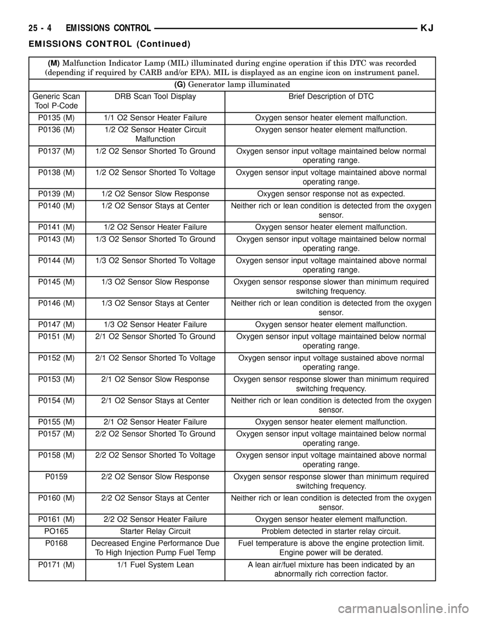
(M)Malfunction Indicator Lamp (MIL) illuminated during engine operation if this DTC was recorded
(depending if required by CARB and/or EPA). MIL is displayed as an engine icon on instrument panel.
(G)Generator lamp illuminated
Generic Scan
Tool P-CodeDRB Scan Tool Display Brief Description of DTC
P0135 (M) 1/1 O2 Sensor Heater Failure Oxygen sensor heater element malfunction.
P0136 (M) 1/2 O2 Sensor Heater Circuit
MalfunctionOxygen sensor heater element malfunction.
P0137 (M) 1/2 O2 Sensor Shorted To Ground Oxygen sensor input voltage maintained below normal
operating range.
P0138 (M) 1/2 O2 Sensor Shorted To Voltage Oxygen sensor input voltage maintained above normal
operating range.
P0139 (M) 1/2 O2 Sensor Slow Response Oxygen sensor response not as expected.
P0140 (M) 1/2 O2 Sensor Stays at Center Neither rich or lean condition is detected from the oxygen
sensor.
P0141 (M) 1/2 O2 Sensor Heater Failure Oxygen sensor heater element malfunction.
P0143 (M) 1/3 O2 Sensor Shorted To Ground Oxygen sensor input voltage maintained below normal
operating range.
P0144 (M) 1/3 O2 Sensor Shorted To Voltage Oxygen sensor input voltage maintained above normal
operating range.
P0145 (M) 1/3 O2 Sensor Slow Response Oxygen sensor response slower than minimum required
switching frequency.
P0146 (M) 1/3 O2 Sensor Stays at Center Neither rich or lean condition is detected from the oxygen
sensor.
P0147 (M) 1/3 O2 Sensor Heater Failure Oxygen sensor heater element malfunction.
P0151 (M) 2/1 O2 Sensor Shorted To Ground Oxygen sensor input voltage maintained below normal
operating range.
P0152 (M) 2/1 O2 Sensor Shorted To Voltage Oxygen sensor input voltage sustained above normal
operating range.
P0153 (M) 2/1 O2 Sensor Slow Response Oxygen sensor response slower than minimum required
switching frequency.
P0154 (M) 2/1 O2 Sensor Stays at Center Neither rich or lean condition is detected from the oxygen
sensor.
P0155 (M) 2/1 O2 Sensor Heater Failure Oxygen sensor heater element malfunction.
P0157 (M) 2/2 O2 Sensor Shorted To Ground Oxygen sensor input voltage maintained below normal
operating range.
P0158 (M) 2/2 O2 Sensor Shorted To Voltage Oxygen sensor input voltage maintained above normal
operating range.
P0159 2/2 O2 Sensor Slow Response Oxygen sensor response slower than minimum required
switching frequency.
P0160 (M) 2/2 O2 Sensor Stays at Center Neither rich or lean condition is detected from the oxygen
sensor.
P0161 (M) 2/2 O2 Sensor Heater Failure Oxygen sensor heater element malfunction.
PO165 Starter Relay Circuit Problem detected in starter relay circuit.
P0168 Decreased Engine Performance Due
To High Injection Pump Fuel TempFuel temperature is above the engine protection limit.
Engine power will be derated.
P0171 (M) 1/1 Fuel System Lean A lean air/fuel mixture has been indicated by an
abnormally rich correction factor.
25 - 4 EMISSIONS CONTROLKJ
EMISSIONS CONTROL (Continued)
Page 1711 of 1803
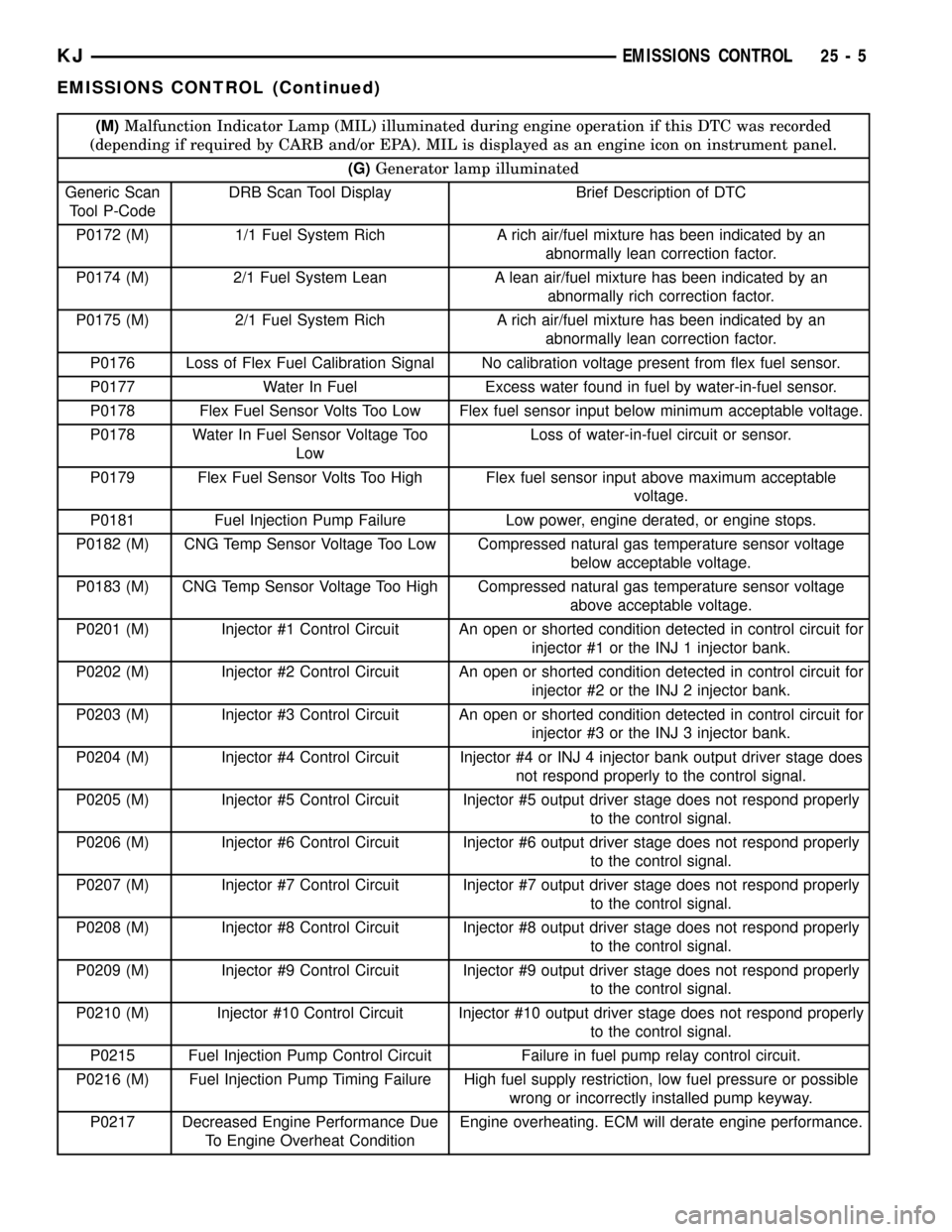
(M)Malfunction Indicator Lamp (MIL) illuminated during engine operation if this DTC was recorded
(depending if required by CARB and/or EPA). MIL is displayed as an engine icon on instrument panel.
(G)Generator lamp illuminated
Generic Scan
Tool P-CodeDRB Scan Tool Display Brief Description of DTC
P0172 (M) 1/1 Fuel System Rich A rich air/fuel mixture has been indicated by an
abnormally lean correction factor.
P0174 (M) 2/1 Fuel System Lean A lean air/fuel mixture has been indicated by an
abnormally rich correction factor.
P0175 (M) 2/1 Fuel System Rich A rich air/fuel mixture has been indicated by an
abnormally lean correction factor.
P0176 Loss of Flex Fuel Calibration Signal No calibration voltage present from flex fuel sensor.
P0177 Water In Fuel Excess water found in fuel by water-in-fuel sensor.
P0178 Flex Fuel Sensor Volts Too Low Flex fuel sensor input below minimum acceptable voltage.
P0178 Water In Fuel Sensor Voltage Too
LowLoss of water-in-fuel circuit or sensor.
P0179 Flex Fuel Sensor Volts Too High Flex fuel sensor input above maximum acceptable
voltage.
P0181 Fuel Injection Pump Failure Low power, engine derated, or engine stops.
P0182 (M) CNG Temp Sensor Voltage Too Low Compressed natural gas temperature sensor voltage
below acceptable voltage.
P0183 (M) CNG Temp Sensor Voltage Too High Compressed natural gas temperature sensor voltage
above acceptable voltage.
P0201 (M) Injector #1 Control Circuit An open or shorted condition detected in control circuit for
injector #1 or the INJ 1 injector bank.
P0202 (M) Injector #2 Control Circuit An open or shorted condition detected in control circuit for
injector #2 or the INJ 2 injector bank.
P0203 (M) Injector #3 Control Circuit An open or shorted condition detected in control circuit for
injector #3 or the INJ 3 injector bank.
P0204 (M) Injector #4 Control Circuit Injector #4 or INJ 4 injector bank output driver stage does
not respond properly to the control signal.
P0205 (M) Injector #5 Control Circuit Injector #5 output driver stage does not respond properly
to the control signal.
P0206 (M) Injector #6 Control Circuit Injector #6 output driver stage does not respond properly
to the control signal.
P0207 (M) Injector #7 Control Circuit Injector #7 output driver stage does not respond properly
to the control signal.
P0208 (M) Injector #8 Control Circuit Injector #8 output driver stage does not respond properly
to the control signal.
P0209 (M) Injector #9 Control Circuit Injector #9 output driver stage does not respond properly
to the control signal.
P0210 (M) Injector #10 Control Circuit Injector #10 output driver stage does not respond properly
to the control signal.
P0215 Fuel Injection Pump Control Circuit Failure in fuel pump relay control circuit.
P0216 (M) Fuel Injection Pump Timing Failure High fuel supply restriction, low fuel pressure or possible
wrong or incorrectly installed pump keyway.
P0217 Decreased Engine Performance Due
To Engine Overheat ConditionEngine overheating. ECM will derate engine performance.
KJEMISSIONS CONTROL 25 - 5
EMISSIONS CONTROL (Continued)
Page 1712 of 1803
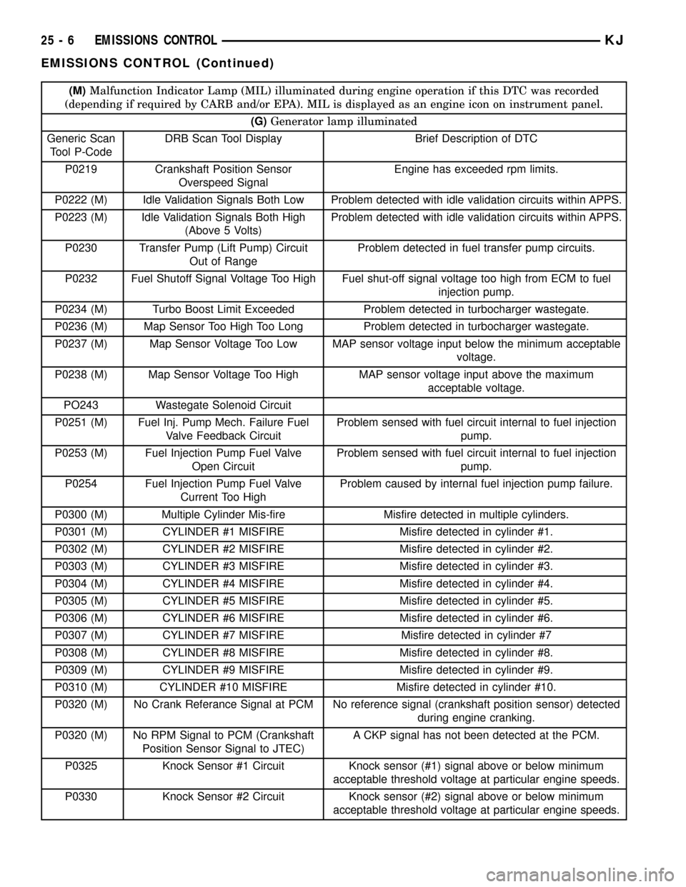
(M)Malfunction Indicator Lamp (MIL) illuminated during engine operation if this DTC was recorded
(depending if required by CARB and/or EPA). MIL is displayed as an engine icon on instrument panel.
(G)Generator lamp illuminated
Generic Scan
Tool P-CodeDRB Scan Tool Display Brief Description of DTC
P0219 Crankshaft Position Sensor
Overspeed SignalEngine has exceeded rpm limits.
P0222 (M) Idle Validation Signals Both Low Problem detected with idle validation circuits within APPS.
P0223 (M) Idle Validation Signals Both High
(Above 5 Volts)Problem detected with idle validation circuits within APPS.
P0230 Transfer Pump (Lift Pump) Circuit
Out of RangeProblem detected in fuel transfer pump circuits.
P0232 Fuel Shutoff Signal Voltage Too High Fuel shut-off signal voltage too high from ECM to fuel
injection pump.
P0234 (M) Turbo Boost Limit Exceeded Problem detected in turbocharger wastegate.
P0236 (M) Map Sensor Too High Too Long Problem detected in turbocharger wastegate.
P0237 (M) Map Sensor Voltage Too Low MAP sensor voltage input below the minimum acceptable
voltage.
P0238 (M) Map Sensor Voltage Too High MAP sensor voltage input above the maximum
acceptable voltage.
PO243 Wastegate Solenoid Circuit
P0251 (M) Fuel Inj. Pump Mech. Failure Fuel
Valve Feedback CircuitProblem sensed with fuel circuit internal to fuel injection
pump.
P0253 (M) Fuel Injection Pump Fuel Valve
Open CircuitProblem sensed with fuel circuit internal to fuel injection
pump.
P0254 Fuel Injection Pump Fuel Valve
Current Too HighProblem caused by internal fuel injection pump failure.
P0300 (M) Multiple Cylinder Mis-fire Misfire detected in multiple cylinders.
P0301 (M) CYLINDER #1 MISFIRE Misfire detected in cylinder #1.
P0302 (M) CYLINDER #2 MISFIRE Misfire detected in cylinder #2.
P0303 (M) CYLINDER #3 MISFIRE Misfire detected in cylinder #3.
P0304 (M) CYLINDER #4 MISFIRE Misfire detected in cylinder #4.
P0305 (M) CYLINDER #5 MISFIRE Misfire detected in cylinder #5.
P0306 (M) CYLINDER #6 MISFIRE Misfire detected in cylinder #6.
P0307 (M) CYLINDER #7 MISFIRE Misfire detected in cylinder #7
P0308 (M) CYLINDER #8 MISFIRE Misfire detected in cylinder #8.
P0309 (M) CYLINDER #9 MISFIRE Misfire detected in cylinder #9.
P0310 (M) CYLINDER #10 MISFIRE Misfire detected in cylinder #10.
P0320 (M) No Crank Referance Signal at PCM No reference signal (crankshaft position sensor) detected
during engine cranking.
P0320 (M) No RPM Signal to PCM (Crankshaft
Position Sensor Signal to JTEC)A CKP signal has not been detected at the PCM.
P0325 Knock Sensor #1 Circuit Knock sensor (#1) signal above or below minimum
acceptable threshold voltage at particular engine speeds.
P0330 Knock Sensor #2 Circuit Knock sensor (#2) signal above or below minimum
acceptable threshold voltage at particular engine speeds.
25 - 6 EMISSIONS CONTROLKJ
EMISSIONS CONTROL (Continued)