Page 1179 of 1803
Fig. 11 ENGINE/TRANSMISSION, 2.4L
8Wa - 91 - 24 8W-91 CONNECTOR/GROUND/SPLICE LOCATIONKJ
CONNECTOR/GROUND/SPLICE LOCATION (Continued)
Page 1180 of 1803
Fig. 12 ENGINE/TRANSMISSION, 2.4L
KJ8W-91 CONNECTOR/GROUND/SPLICE LOCATION8Wa-91-25
CONNECTOR/GROUND/SPLICE LOCATION (Continued)
Page 1181 of 1803
Fig. 13 ENGINE COMPARTMENT, 2.4L
8Wa - 91 - 26 8W-91 CONNECTOR/GROUND/SPLICE LOCATIONKJ
CONNECTOR/GROUND/SPLICE LOCATION (Continued)
Page 1182 of 1803
Fig. 14 RIGHT REAR ENGINE COMPARTMENT, 2.4L
KJ8W-91 CONNECTOR/GROUND/SPLICE LOCATION8Wa-91-27
CONNECTOR/GROUND/SPLICE LOCATION (Continued)
Page 1183 of 1803
Fig. 15 ENGINE, 2.4L
8Wa - 91 - 28 8W-91 CONNECTOR/GROUND/SPLICE LOCATIONKJ
CONNECTOR/GROUND/SPLICE LOCATION (Continued)
Page 1184 of 1803
Fig. 16 RIGHT REAR ENGINE COMPARTMENT, 2.4L
KJ8W-91 CONNECTOR/GROUND/SPLICE LOCATION8Wa-91-29
CONNECTOR/GROUND/SPLICE LOCATION (Continued)
Page 1298 of 1803

ENGINE
TABLE OF CONTENTS
page page
ENGINE - 2.4L
DESCRIPTION..........................3
DIAGNOSIS AND TESTING
DIAGNOSIS AND TESTING - CYLINDER
COMBUSTION PRESSURE LEAKAGE
TEST................................3
DIAGNOSIS AND TESTING - CYLINDER
COMPRESSION PRESSURE TEST.........3
DIAGNOSIS AND TESTING - ENGINE OIL
LEAK INSPECTION.....................4
DIAGNOSIS AND TESTING - ENGINE.......5
DIAGNOSIS AND TESTING - ENGINE
DIAGNOSIS - PERFORMANCE............5
DIAGNOSIS AND TESTING - ENGINE
MECHANICAL.........................7
STANDARD PROCEDURE
STANDARD PROCEDURE - ENGINE CORE
AND OIL GALLERY PLUGS...............9
STANDARD PROCEDURE - REPAIR OF
DAMAGED OR WORN THREADS..........9
STANDARD PROCEDURE - HYDROSTATIC
LOCKED ENGINE......................9
STANDARD PROCEDURE - FORM-IN-
PLACE GASKETS AND SEALERS.........10
STANDARD PROCEDURE - ENGINE
GASKET SURFACE PREPARATION........11
STANDARD PROCEDURE - MEASURING
BEARING CLEARANCE USING
PLASTIGAGE.........................11
REMOVAL - ENGINE ASSEMBLY...........12
INSTALLATION - ENGINE ASSEMBLY........12
SPECIFICATIONS
SPECIFICATIONS - 2.4L ENGINE.........13
SPECIFICATIONS - TORQUE............16
SPECIAL TOOLS
2.4L ENGINE.........................17
AIR CLEANER ELEMENT
REMOVAL - 2.4L........................19
INSTALLATION - 2.4L....................19
CYLINDER HEAD
DESCRIPTION.........................19
OPERATION...........................19
DIAGNOSIS AND TESTING - CYLINDER HEAD
GASKET............................19
REMOVAL - CYLINDER HEAD.............20
CLEANING............................20
INSPECTION..........................21
INSTALLATION - CYLINDER HEAD..........21CAMSHAFT OIL SEAL(S)
REMOVAL.............................22
INSTALLATION.........................22
CAMSHAFT(S)
DESCRIPTION.........................23
OPERATION...........................23
STANDARD PROCEDURE - CAMSHAFT
END-PLAY...........................23
REMOVAL.............................24
CLEANING............................24
INSPECTION..........................25
INSTALLATION.........................25
CYLINDER HEAD COVER
REMOVAL.............................26
CLEANING............................26
INSPECTION..........................26
INSTALLATION.........................26
INTAKE/EXHAUST VALVES & SEATS
DESCRIPTION.........................27
CLEANING............................27
VALVE SPRINGS
REMOVAL
REMOVAL - CYLINDER HEAD ON.........27
REMOVAL - CYLINDER HEAD OFF........27
INSPECTION..........................28
INSTALLATION
INSTALLATION - CYLINDER HEAD ON.....28
INSTALLATION - CYLINDER HEAD OFF....28
HYDRAULIC LIFTERS
DIAGNOSIS AND TESTING - LASH ADJUSTER
(TAPPET) NOISE DIAGNOSIS............28
REMOVAL.............................29
INSTALLATION.........................29
ROCKER ARMS
REMOVAL.............................29
INSPECTION..........................30
INSTALLATION.........................30
ENGINE BLOCK
DESCRIPTION.........................30
STANDARD PROCEDURE
STANDARD PROCEDURE - PISTON TO
CYLINDER BORE FITTING..............30
STANDARD PROCEDURE - CYLINDER
BORE HONING.......................31
CLEANING............................31
INSPECTION..........................32
CONNECTING ROD BEARINGS
STANDARD PROCEDURE
CONNECTING ROD - FITTING...........32
KJENGINE 9s - 1
Page 1300 of 1803

ENGINE - 2.4L
DESCRIPTION
The 2.4 Liter (148 cu. in.) in-line four cylinder
engine is a double over head camshaft with hydraulic
lifters and four valve per cylinder design. The engine
is free-wheeling; meaning it has provisions for piston-
to-valve clearance. However valve-to-valve interference
can occur, if camshafts are rotated independently.
The cylinders are numbered from front of the
engine to the rear. The firing order is 1±3±4±2.
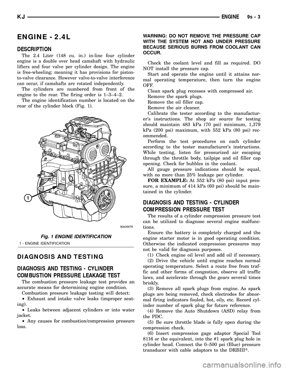
The engine identification number is located on the
rear of the cylinder block (Fig. 1).
DIAGNOSIS AND TESTING
DIAGNOSIS AND TESTING - CYLINDER
COMBUSTION PRESSURE LEAKAGE TEST
The combustion pressure leakage test provides an
accurate means for determining engine condition.
Combustion pressure leakage testing will detect:
²Exhaust and intake valve leaks (improper seat-
ing).
²Leaks between adjacent cylinders or into water
jacket.
²Any causes for combustion/compression pressure
loss.WARNING: DO NOT REMOVE THE PRESSURE CAP
WITH THE SYSTEM HOT AND UNDER PRESSURE
BECAUSE SERIOUS BURNS FROM COOLANT CAN
OCCUR.
Check the coolant level and fill as required. DO
NOT install the pressure cap.
Start and operate the engine until it attains nor-
mal operating temperature, then turn the engine
OFF.
Clean spark plug recesses with compressed air.
Remove the spark plugs.
Remove the oil filler cap.
Remove the air cleaner.
Calibrate the tester according to the manufactur-
er's instructions. The shop air source for testing
should maintain 483 kPa (70 psi) minimum, 1,379
kPa (200 psi) maximum, with 552 kPa (80 psi) rec-
ommended.
Perform the test procedures on each cylinder
according to the tester manufacturer's instructions.
While testing, listen for pressurized air escaping
through the throttle body, tailpipe and oil filler cap
opening. Check for bubbles in the coolant.
All gauge pressure indications should be equal,
with no more than 25% leakage per cylinder.
FOR EXAMPLE:At 552 kPa (80 psi) input pres-
sure, a minimum of 414 kPa (60 psi) should be main-
tained in the cylinder.
DIAGNOSIS AND TESTING - CYLINDER
COMPRESSION PRESSURE TEST
The results of a cylinder compression pressure test
can be utilized to diagnose several engine malfunc-
tions.
Ensure the battery is completely charged and the
engine starter motor is in good operating condition.
Otherwise the indicated compression pressures may
not be valid for diagnosis purposes.
(1) Check engine oil level and add oil if necessary.
(2) Drive the vehicle until engine reaches normal
operating temperature. Select a route free from traf-
fic and other forms of congestion, observe all traffic
laws, and accelerate through the gears several times
briskly.
(3) Remove all spark plugs from engine. As spark
plugs are being removed, check electrodes for abnor-
mal firing indicators fouled, hot, oily, etc. Record cyl-
inder number of spark plug for future reference.
(4) Remove the Auto Shutdown (ASD) relay from
the PDC.
(5) Be sure throttle blade is fully open during the
compression check.
(6) Insert compression gage adaptor Special Tool
8116 or the equivalent, into the #1 spark plug hole in
cylinder head. Connect the 0±500 psi (Blue) pressure
transducer with cable adaptors to the DRBIIIt.
Fig. 1 ENGINE IDENTIFICATION
1 - ENGINE IDENTIFICATION
KJENGINE9s-3