Page 1552 of 1803

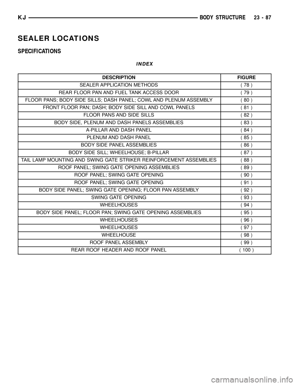
SEALER LOCATIONS
SPECIFICATIONS
INDEX
DESCRIPTION FIGURE
SEALER APPLICATION METHODS ( 78 )
REAR FLOOR PAN AND FUEL TANK ACCESS DOOR ( 79 )
FLOOR PANS; BODY SIDE SILLS; DASH PANEL; COWL AND PLENUM ASSEMBLY ( 80 )
FRONT FLOOR PAN; DASH; BODY SIDE SILL AND COWL PANELS ( 81 )
FLOOR PANS AND SIDE SILLS ( 82 )
BODY SIDE, PLENUM AND DASH PANELS ASSEMBLIES ( 83 )
A-PILLAR AND DASH PANEL ( 84 )
PLENUM AND DASH PANEL ( 85 )
BODY SIDE PANEL ASSEMBLIES ( 86 )
BODY SIDE SILL; WHEELHOUSE; B-PILLAR ( 87 )
TAIL LAMP MOUNTING AND SWING GATE STRIKER REINFORCEMENT ASSEMBLIES ( 88 )
ROOF PANEL; SWING GATE OPENING ASSEMBLIES ( 89 )
ROOF PANEL; SWING GATE OPENING ( 90 )
ROOF PANEL; SWING GATE OPENING ( 91 )
BODY SIDE PANEL; SWING GATE OPENING; FLOOR PAN ASSEMBLY ( 92 )
SWING GATE OPENING ( 93 )
WHEELHOUSES ( 94 )
BODY SIDE PANEL; FLOOR PAN; SWING GATE OPENING ASSEMBLIES ( 95 )
WHEELHOUSES ( 96 )
WHEELHOUSES ( 97 )
WHEELHOUSE ( 98 )
ROOF PANEL ASSEMBLY ( 99 )
REAR ROOF HEADER AND ROOF PANEL ( 100 )
KJBODY STRUCTURE 23 - 87
Page 1564 of 1803
Fig. 89 ROOF PANEL & BODY SIDE SILL ASSEMBLY
KJBODY STRUCTURE 23 - 99
SEALER LOCATIONS (Continued)
Page 1566 of 1803
Fig. 91 ROOF PANEL; SWING GATE OPENING
KJBODY STRUCTURE 23 - 101
SEALER LOCATIONS (Continued)
Page 1574 of 1803
Fig. 99 ROOF PANEL ASSEMBLY
KJBODY STRUCTURE 23 - 109
SEALER LOCATIONS (Continued)
Page 1575 of 1803
Fig. 100 ROOF PANEL/REAR ROOF HEADER
23 - 110 BODY STRUCTUREKJ
SEALER LOCATIONS (Continued)
Page 1609 of 1803
LUGGAGE RACK
REMOVAL
(1) Using a trim stick C-4755 or equivalent,
remove the roof rack covers. (Fig. 8)
(2) Remove the bolts and remove the roof rack.
(Fig. 7)
INSTALLATION
(1) Install the roof rack and install the bolts.
(2) Tighten the bolts to 8 N´m (75 in. lbs.).
(3) Snap on the roof rack covers.
REAR WHEELHOUSE SPLASH
SHIELD
REMOVAL
(1) Remove the wheel flare moldings. (Refer to 23 -
BODY/EXTERIOR/REAR WHEEL OPENING
FLARE MOLDING - REMOVAL)
(2) Remove the three push pin fasteners and
remove the splash shield. (Fig. 9)
INSTALLATION
(1) Install the splash shield and install the three
push pin fasteners.
(2) Install the wheel flare moldings. (Refer to 23 -
BODY/EXTERIOR/REAR WHEEL OPENING
FLARE MOLDING - INSTALLATION)
Fig. 7 LUGGAGE RACK
1 - BOLTS (4)
2 - RACK RAIL
Fig. 8 RACK COVERS
1 - COVER
2 - BOLTS
3 - ROOF PANEL
4 - KNURLED NUT
5 - ROOF RACK
Fig. 9 WHEELHOUSE SPLASH SHIELD
1 - SPLASH SHIELD
2 - PUSH PIN FASTENERS (3)
23 - 144 EXTERIORKJ
Page 1624 of 1803

HEADLINER
REMOVAL
(1) Remove the a-pillar trim. (Refer to 23 - BODY/
INTERIOR/A-PILLAR TRIM AND GRAB HANDLE -
REMOVAL)
(2) Remove the visors. (Refer to 23 - BODY/INTE-
RIOR/SUN VISOR - REMOVAL)
(3) Remove the sun visor support. (Refer to 23 -
BODY/INTERIOR/SUN VISOR SUPPORT -
REMOVAL)
(4) Remove the overhead console. (Refer to 8 -
ELECTRICAL/OVERHEAD CONSOLE - REMOVAL)
(5) Cut rear washer hose at the mark about half-
way up the a-pillar.
(6) Remove the upper b-pillar trim. (Refer to 23 -
BODY/INTERIOR/B-PILLAR UPPER TRIM -
REMOVAL)
(7) Remove the assist handles. (Refer to 23 -
BODY/INTERIOR/ASSIST HANDLE - REMOVAL)
(8) Remove the quarter trim. (Refer to 23 - BODY/
INTERIOR/QUARTER TRIM PANEL - REMOVAL)
(9) Disconnect the electrical connector along the
left d-pillar and remove the ground wire.
(10) Remove the dome light in the rear.
(11) Remove the sunroof opening trim lace, if
equipped. (Refer to 23 - BODY/SUNROOF/OPENING
TRIM LACE - REMOVAL)(12) Remove the rear washer nozzle.
(13) Remove the headliner.
INSTALLATION
(1) Install the headliner.
(2) Install the assist handles. (Refer to 23 - BODY/
INTERIOR/ASSIST HANDLE - INSTALLATION)
(3) Install the visors. (Refer to 23 - BODY/INTERI-
OR/SUN VISOR - INSTALLATION)
(4) Install the visor supports. (Refer to 23 - BODY/
INTERIOR/SUN VISOR SUPPORT - INSTALLA-
TION)
(5) Install the overhead console. (Refer to 8 -
ELECTRICAL/OVERHEAD CONSOLE - INSTALLA-
TION)
(6) Connect the rear washer hose, previously cut,
with a hose junction.
(7) Install the a-pillar trim and grab handles.
(Refer to 23 - BODY/INTERIOR/A-PILLAR TRIM -
INSTALLATION)
(8) Install the upper b-pillar trim. (Refer to 23 -
BODY/INTERIOR/B-PILLAR UPPER TRIM -
INSTALLATION)
(9) Install the rear washer nozzle.
(10) Connect the electrical connector and ground
wire at the left d-pillar.
(11) Install the quarter trim panels. (Refer to 23 -
BODY/INTERIOR/QUARTER TRIM PANEL -
INSTALLATION)
(12) Install the rear dome light.
(13) Install the sunroof opening trim lace, if
equipped. (Refer to 23 - BODY/SUNROOF/OPENING
TRIM LACE - INSTALLATION)
QUARTER TRIM PANEL
REMOVAL
(1) Using a trim stick C-4755 or equivalent,
remove the rear header trim.
(2) Using a trim stick C-4755 or equivalent,
remove the rear sill plate.
(3) Remove the hook pin type connector.
(4) Fold down the rear seat.
(5) Remove the seat belt anchor and pivot. (Refer
to 8 - ELECTRICAL/RESTRAINTS/SEAT BELT &
RETRACTOR - REMOVAL)
(6) Remove the belt access panel. (Fig. 4)
(7) Remove the storage cover.
(8) Disconnect the 12v power supply electrical con-
nector, if equipped.
INSTALLATION
(1) Position the 12v power supply electrical con-
nector, if equipped.
(2) Install the storage cover.
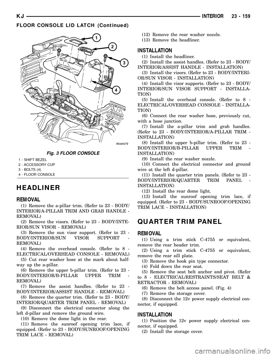
Fig. 3 FLOOR CONSOLE
1 - SHIFT BEZEL
2 - ACCESSORY CUP
3 - BOLTS (4)
4 - FLOOR CONSOLE
KJINTERIOR 23 - 159
FLOOR CONSOLE LID LATCH (Continued)
Page 1627 of 1803

PAINT
TABLE OF CONTENTS
page page
PAINT
SPECIFICATIONS - PAINT CODES.........162
PAINT CODE
DESCRIPTION........................162
BASE COAT/CLEAR COAT FINISH
DESCRIPTION........................162PAINT TOUCH-UP
DESCRIPTION........................163
FINESSE SANDING/BUFFING & POLISHING
DESCRIPTION........................163
PAINT
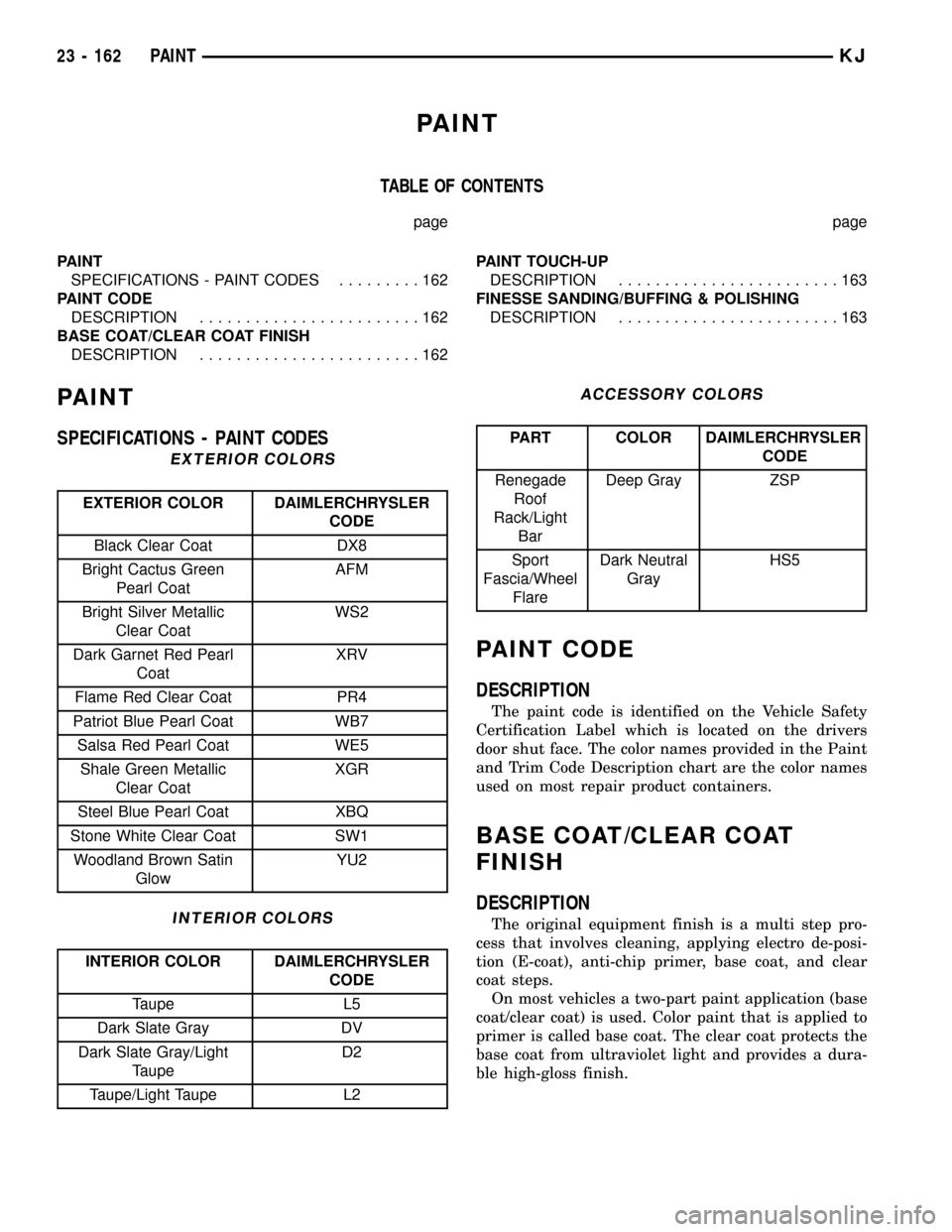
SPECIFICATIONS - PAINT CODES
EXTERIOR COLORS
EXTERIOR COLOR DAIMLERCHRYSLER
CODE
Black Clear Coat DX8
Bright Cactus Green
Pearl CoatAFM
Bright Silver Metallic
Clear CoatWS2
Dark Garnet Red Pearl
CoatXRV
Flame Red Clear Coat PR4
Patriot Blue Pearl Coat WB7
Salsa Red Pearl Coat WE5
Shale Green Metallic
Clear CoatXGR
Steel Blue Pearl Coat XBQ
Stone White Clear Coat SW1
Woodland Brown Satin
GlowYU2
INTERIOR COLORS
INTERIOR COLOR DAIMLERCHRYSLER
CODE
Taupe L5
Dark Slate Gray DV
Dark Slate Gray/Light
TaupeD2
Taupe/Light Taupe L2
ACCESSORY COLORS
PART COLOR DAIMLERCHRYSLER
CODE
Renegade
Roof
Rack/Light
BarDeep Gray ZSP
Sport
Fascia/Wheel
FlareDark Neutral
GrayHS5
PAINT CODE
DESCRIPTION
The paint code is identified on the Vehicle Safety
Certification Label which is located on the drivers
door shut face. The color names provided in the Paint
and Trim Code Description chart are the color names
used on most repair product containers.
BASE COAT/CLEAR COAT
FINISH
DESCRIPTION
The original equipment finish is a multi step pro-
cess that involves cleaning, applying electro de-posi-
tion (E-coat), anti-chip primer, base coat, and clear
coat steps.
On most vehicles a two-part paint application (base
coat/clear coat) is used. Color paint that is applied to
primer is called base coat. The clear coat protects the
base coat from ultraviolet light and provides a dura-
ble high-gloss finish.
23 - 162 PAINTKJ