2002 JEEP LIBERTY key battery
[x] Cancel search: key batteryPage 699 of 1803

(2) Install and tighten the two screws that secure
the alarm siren module to the front extension of the
right front wheel house panel. Tighten the screws to
6 N´m (50 in. lbs.).
(3) Reconnect the headlamp and dash wire harness
connector for the alarm siren module to the module
connector receptacle.
(4) Reconnect the battery negative cable.
NOTE: If the alarm siren module has been replaced
with a new unit, the new unit MUST be configured
in the Intrusion Transceiver Module (ITM) before the
Vehicle Theft Security System can operate as
designed. The use of a DRBIIITscan tool is required
to configure the alarm siren module settings in the
ITM. Refer to the appropriate diagnostic informa-
tion.
TRANSPONDER KEY
DESCRIPTION
Each ignition key used in the Sentry Key Immobi-
lizer System (SKIS) has an integral transponder chip
(Fig. 15). Ignition keys with this feature can be
readily identified by a gray rubber cap molded onto
the head of the key, while conventional ignition keys
have a black molded rubber cap. The transponderchip is concealed beneath the molded rubber cap,
where it is molded within a plastic mount into the
head of the metal key. In addition to being cut to
match the mechanical coding of the ignition lock cyl-
inder, each new Sentry Key has a unique transpon-
der identification code permanently programmed into
it by the manufacturer. The Sentry Key transponder
cannot be adjusted or repaired. If faulty or damaged,
the entire key must be replaced.
OPERATION
When the ignition switch is turned to the On posi-
tion, the Sentry Key Immobilizer Module (SKIM)
communicates through its antenna with the Sentry
Key transponder using a Radio Frequency (RF) sig-
nal. The SKIM then listens for a RF response from
the transponder through the same antenna. The Sen-
try Key transponder chip is within the range of the
SKIM transceiver antenna ring when it is inserted
into the ignition lock cylinder. The SKIM determines
whether a valid key is present in the ignition lock
cylinder based upon the response from the transpon-
der. If a valid key is detected, that fact is communi-
cated by the SKIM to the Powertrain Control Module
(PCM) over the Programmable Communications
Interface (PCI) data bus, and the PCM allows the
engine to continue running. If the PCM receives an
invalid key message, or receives no message from the
SKIM over the PCI data bus, the engine will be dis-
abled after about two seconds of operation. The Elec-
troMechanical Instrument Cluster (EMIC) will also
respond to the invalid key message on the PCI data
bus by flashing the SKIS indicator on and off.
Fig. 14 Siren Remove/Install
1 - SCREW (2)
2 - WIRE HARNESS CONNECTOR
3 - SIREN
Fig. 15 Sentry Key Immobilizer Transponder
1 - MOLDED CAP
2 - TRANSPONDER CHIP
3 - MOLDED CAP REMOVED
4 - TRANSPONDER KEY
8Q - 18 VEHICLE THEFT SECURITYKJ
SIREN (Continued)
Page 743 of 1803

REMOVAL
(1) Disconnect and isolate the battery negative
cable.
(2) Remove the rear wiper arm from the rear
wiper motor output shaft. (Refer to 8 - ELECTRI-
CAL/REAR WIPERS/WASHERS/REAR WIPER ARM
- REMOVAL).
(3) Using a small thin-bladed tool, gently pry at
the notch in the base of the rear wiper motor output
shaft bezel to unsnap the nut cover from the bezel
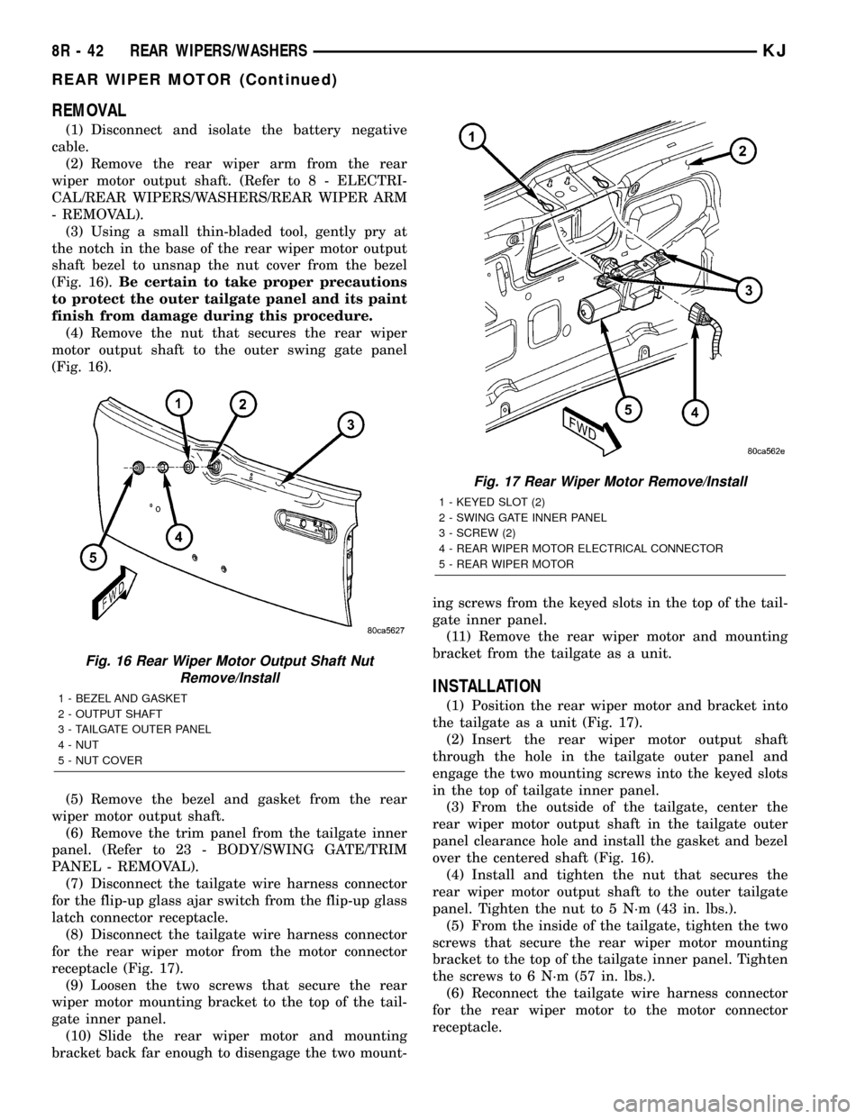
(Fig. 16).Be certain to take proper precautions
to protect the outer tailgate panel and its paint
finish from damage during this procedure.
(4) Remove the nut that secures the rear wiper
motor output shaft to the outer swing gate panel
(Fig. 16).
(5) Remove the bezel and gasket from the rear
wiper motor output shaft.
(6) Remove the trim panel from the tailgate inner
panel. (Refer to 23 - BODY/SWING GATE/TRIM
PANEL - REMOVAL).
(7) Disconnect the tailgate wire harness connector
for the flip-up glass ajar switch from the flip-up glass
latch connector receptacle.
(8) Disconnect the tailgate wire harness connector
for the rear wiper motor from the motor connector
receptacle (Fig. 17).
(9) Loosen the two screws that secure the rear
wiper motor mounting bracket to the top of the tail-
gate inner panel.
(10) Slide the rear wiper motor and mounting
bracket back far enough to disengage the two mount-ing screws from the keyed slots in the top of the tail-
gate inner panel.
(11) Remove the rear wiper motor and mounting
bracket from the tailgate as a unit.
INSTALLATION
(1) Position the rear wiper motor and bracket into
the tailgate as a unit (Fig. 17).
(2) Insert the rear wiper motor output shaft
through the hole in the tailgate outer panel and
engage the two mounting screws into the keyed slots
in the top of tailgate inner panel.
(3) From the outside of the tailgate, center the
rear wiper motor output shaft in the tailgate outer
panel clearance hole and install the gasket and bezel
over the centered shaft (Fig. 16).
(4) Install and tighten the nut that secures the
rear wiper motor output shaft to the outer tailgate
panel. Tighten the nut to 5 N´m (43 in. lbs.).
(5) From the inside of the tailgate, tighten the two
screws that secure the rear wiper motor mounting
bracket to the top of the tailgate inner panel. Tighten
the screws to 6 N´m (57 in. lbs.).
(6) Reconnect the tailgate wire harness connector
for the rear wiper motor to the motor connector
receptacle.
Fig. 16 Rear Wiper Motor Output Shaft Nut
Remove/Install
1 - BEZEL AND GASKET
2 - OUTPUT SHAFT
3 - TAILGATE OUTER PANEL
4 - NUT
5 - NUT COVER
Fig. 17 Rear Wiper Motor Remove/Install
1 - KEYED SLOT (2)
2 - SWING GATE INNER PANEL
3 - SCREW (2)
4 - REAR WIPER MOTOR ELECTRICAL CONNECTOR
5 - REAR WIPER MOTOR
8R - 42 REAR WIPERS/WASHERSKJ
REAR WIPER MOTOR (Continued)
Page 830 of 1803

8W-15 GROUND DISTRIBUTION
Component Page
A/C Compressor Clutch...................8Wa-15-6
A/C Low Pressure Switch.................8Wa-15-3
A/C- Heater Control...................8Wa-15-7, 8
Airbag Control Module...................8Wa-15-7
Ash Receiver Lamp.....................8Wa-15-8
Battery.............................8Wa-15-2
Blend Door Actuator.....................8Wa-15-8
Blower Motor Relay.....................8Wa-15-4
Body Control Module....................8Wa-15-8
Brake Lamp Switch.....................8Wa-15-8
Cabin Heater.........................8Wa-15-6
Capacitor............................8Wa-15-2
Center High Mounted Stop Lamp...........8Wa-15-14
Cigar Lighter.........................8Wa-15-8
Compass Mini-Trip Computer..............8Wa-15-14
Controller Antilock Brake.................8Wa-15-2
Data Link Connector....................8Wa-15-2
Engine Control Module...................8Wa-15-7
Engine Coolant Level Sensor...............8Wa-15-6
Flip-Up Glass Release Motor..............8Wa-15-14
Front Wiper Motor......................8Wa-15-3
Fuel Heater..........................8Wa-15-6
Fuel Heater Relay......................8Wa-15-4
Fuel Pump Module.....................8Wa-15-15
G100.............................8Wa-15-2, 7
G101...............................8Wa-15-6
G102...............................8Wa-15-2
G103...............................8Wa-15-6
G104...............................8Wa-15-7
G105...............................8Wa-15-2
G106...............................8Wa-15-2
G110...............................8Wa-15-2
G111 .............................8Wa-15-3, 4
G112...............................8Wa-15-3
G200...............................8Wa-15-7
G201...............................8Wa-15-7
G202...............................8Wa-15-8
G300............................8Wa-15-9, 11
G301............................8Wa-15-9, 10
G302............................8Wa-15-9, 12
G310.........................8Wa-15-13, 14, 15
G311 ..............................8Wa-15-14
G312..............................8Wa-15-14
G320..............................8Wa-15-15
Hazard Switch/Combination Flasher..........8Wa-15-8
Headlamp Leveling Switch................8Wa-15-8
Heated Seat Module....................8Wa-15-10
High Note Horn.......................8Wa-15-3
Hood Ajar Switch.......................8Wa-15-4
Ignition Switch........................8Wa-15-8
Instrument Cluster.....................8Wa-15-8
Intrusion Sensor......................8Wa-15-14
Junction Block........................8Wa-15-8
Left Door Lock Switch...................8Wa-15-11
Left Fog Lamp........................8Wa-15-5
Left Front Door Ajar Switch...............8Wa-15-11
Left Front Door Lock Motor/Ajar Switch.......8Wa-15-11
Left Front Door Speaker..................8Wa-15-7
Left Front Park/Turn Signal Lamp...........8Wa-15-5
Left Headlamp........................8Wa-15-3
Left Heated Seat Assembly...............8Wa-15-10
Left Heated Seat Switch.................8Wa-15-10Component Page
Left Leveling Motor.....................8Wa-15-3
Left Position Lamp.....................8Wa-15-3
Left Power Mirror.....................8Wa-15-11
Left Power Seat Switch..................8Wa-15-10
Left Rear Door Ajar Switch...............8Wa-15-11
Left Rear Door Lock Motor/Ajar Switch.......8Wa-15-11
Left Side Impact Airbag Control Module........8Wa-15-9
Left Side Repeater Lamp..................8Wa-15-5
Left Tail/Stop Lamp....................8Wa-15-15
License Lamp........................8Wa-15-15
Line Pressure Sensor....................8Wa-15-2
Low Note Horn........................8Wa-15-3
Multi- Function Switch...................8Wa-15-8
Oxygen Sensor 1/2 Downstream.............8Wa-15-6
Oxygen Sensor 2/2 Downstream.............8Wa-15-6
Power Mirror Switch.................8Wa-15-11, 12
Power Outlet.........................8Wa-15-8
Power Steering Pressure Switch.............8Wa-15-6
Power Window Master Switch.............8Wa-15-10
Powertrain Control Module................8Wa-15-2
Radiator Fan Motor.....................8Wa-15-3
Radiator Fan Relay.....................8Wa-15-3
Radio..............................8Wa-15-7
Radio Choke..........................8Wa-15-9
Rear Power Outlet.....................8Wa-15-15
Rear Window Defogger..................8Wa-15-14
Rear Wiper Motor.....................8Wa-15-14
Red Brake Warning Indicator Switch..........8Wa-15-4
Right Door Lock Switch..................8Wa-15-12
Right Fog Lamp.......................8Wa-15-5
Right Front Door Ajar Switch..............8Wa-15-12
Right Front Door Lock Motor/Ajar Switch......8Wa-15-12
Right Front Door Speaker.................8Wa-15-7
Right Front Park/Turn Signal Lamp..........8Wa-15-5
Right Headlamp.......................8Wa-15-4
Right Heated Seat Assembly..............8Wa-15-10
Right Heated Seat Switch................8Wa-15-10
Right Leveling Motor....................8Wa-15-4
Right Position Lamp....................8Wa-15-4
Right Power Mirror....................8Wa-15-12
Right Power Seat Switch.................8Wa-15-10
Right Rear Door Ajar Switch..............8Wa-15-12
Right Rear Door Lock Motor/Ajar Switch......8Wa-15-12
Right Side Impact Airbag Control Module.......8Wa-15-9
Right Side Repeater Lamp.................8Wa-15-5
Right Tail/Stop Lamp...................8Wa-15-15
Sentry Key Immobilizer Module.............8Wa-15-8
Shifter Assembly.......................8Wa-15-9
Siren...............................8Wa-15-4
Speed Control Servo.....................8Wa-15-3
Starter Motor Relay.....................8Wa-15-4
Sunroof Motor........................8Wa-15-14
Tailgate Flip-Up Ajar Switch..............8Wa-15-14
Trailer Tow Brake Lamp Relay.............8Wa-15-13
Trailer Tow Connector...................8Wa-15-13
Trailer Tow Left Turn Relay...............8Wa-15-13
Trailer Tow Relay......................8Wa-15-13
Trailer Tow Right Turn Relay..............8Wa-15-13
Transmission Control Module...............8Wa-15-2
Transmission Control Relay................8Wa-15-4
Washer Fluid Level Switch................8Wa-15-3
KJ8W-15 GROUND DISTRIBUTION8Wa-15-1
Page 1270 of 1803

INSTALLATION
CAUTION: To prevent severe damage to the Crank-
shaft, Damper or Special Tool 8512, thoroughly
clean the damper bore and the crankshaft nose
before installing Damper.
(1) Align crankshaft damper slot with key in
crankshaft. Slide damper onto crankshaft slightly.
CAUTION: Special Tool 8512A, is assembled in a
specific sequence. Failure to assemble this tool in
this sequence can result in tool failure and severe
damage to either the tool or the crankshaft.
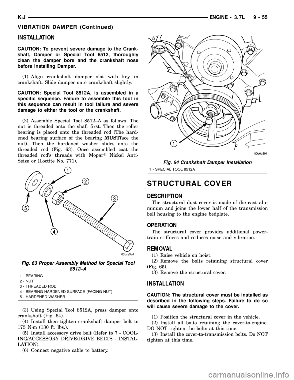
(2) Assemble Special Tool 8512±A as follows, The
nut is threaded onto the shaft first. Then the roller
bearing is placed onto the threaded rod (The hard-
ened bearing surface of the bearingMUSTface the
nut). Then the hardened washer slides onto the
threaded rod (Fig. 63). Once assembled coat the
threaded rod's threads with MopartNickel Anti-
Seize or (Loctite No. 771).
(3) Using Special Tool 8512A, press damper onto
crankshaft (Fig. 64).
(4) Install then tighten crankshaft damper bolt to
175 N´m (130 ft. lbs.).
(5) Install accessory drive belt (Refer to 7 - COOL-
ING/ACCESSORY DRIVE/DRIVE BELTS - INSTAL-
LATION).
(6) Connect negative cable to battery.
STRUCTURAL COVER
DESCRIPTION
The structural dust cover is made of die cast alu-
minum and joins the lower half of the transmission
bell housing to the engine bedplate.
OPERATION
The structural cover provides additional power-
train stiffness and reduces noise and vibration.
REMOVAL
(1) Raise vehicle on hoist.
(2) Remove the bolts retaining structural cover
(Fig. 65).
(3) Remove the structural cover.
INSTALLATION
CAUTION: The structural cover must be installed as
described in the following steps. Failure to do so
will cause severe damage to the cover.
(1) Position the structural cover in the vehicle.
(2) Install all bolts retaining the cover-to-engine.
DO NOT tighten the bolts at this time.
(3) Install the cover-to-transmission bolts. Do NOT
tighten at this time.
Fig. 63 Proper Assembly Method for Special Tool
8512±A
1 - BEARING
2 - NUT
3 - THREADED ROD
4 - BEARING HARDENED SURFACE (FACING NUT)
5 - HARDENED WASHER
Fig. 64 Crankshaft Damper Installation
1 - SPECIAL TOOL 8512A
KJENGINE - 3.7L 9 - 55
VIBRATION DAMPER (Continued)
Page 1346 of 1803

instrument panel on either a CCD or PCI bus circuit
(depending on vehicle line) to operate the oil pressure
gauge and the check gauges lamp. Ground for the
sensor is provided by the PCM through a low-noise
sensor return.
OIL PUMP
REMOVAL
(1) Disconnect negative cable from battery.
(2) Remove timing belt. (Refer to 9 - ENGINE/
VALVE TIMING/TIMING BELT/CHAIN AND
SPROCKETS - REMOVAL)
(3) Remove timing belt rear cover. (Refer to 9 -
ENGINE/VALVE TIMING/TIMING BELT / CHAIN
COVER(S) - REMOVAL)
(4) Remove oil pan. (Refer to 9 - ENGINE/LUBRI-
CATION/OIL PAN - REMOVAL)
(5) Remove crankshaft sprocket using Special
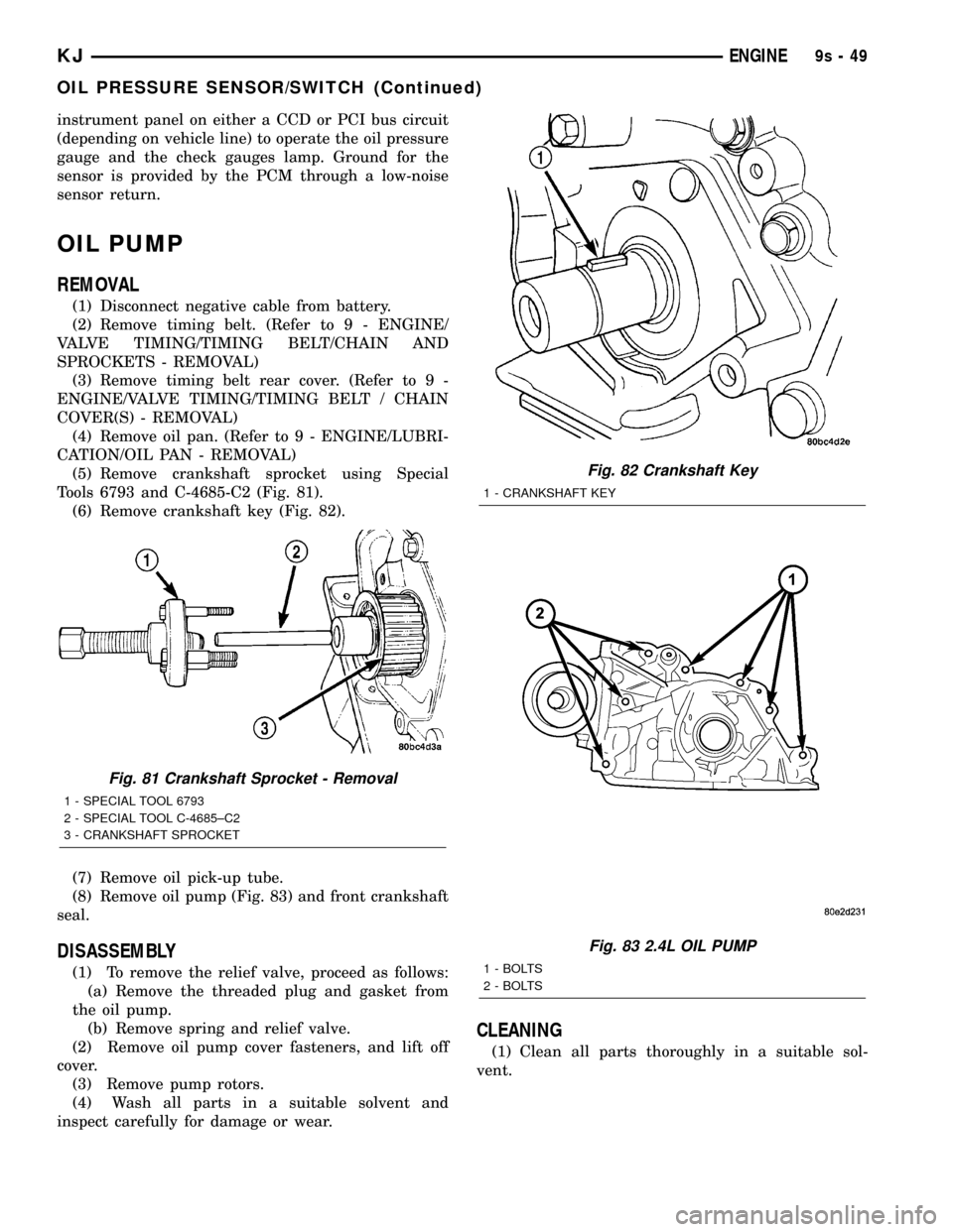
Tools 6793 and C-4685-C2 (Fig. 81).
(6) Remove crankshaft key (Fig. 82).
(7) Remove oil pick-up tube.
(8) Remove oil pump (Fig. 83) and front crankshaft
seal.
DISASSEMBLY
(1) To remove the relief valve, proceed as follows:
(a) Remove the threaded plug and gasket from
the oil pump.
(b) Remove spring and relief valve.
(2) Remove oil pump cover fasteners, and lift off
cover.
(3) Remove pump rotors.
(4) Wash all parts in a suitable solvent and
inspect carefully for damage or wear.
CLEANING
(1) Clean all parts thoroughly in a suitable sol-
vent.
Fig. 81 Crankshaft Sprocket - Removal
1 - SPECIAL TOOL 6793
2 - SPECIAL TOOL C-4685±C2
3 - CRANKSHAFT SPROCKET
Fig. 82 Crankshaft Key
1 - CRANKSHAFT KEY
Fig. 83 2.4L OIL PUMP
1 - BOLTS
2 - BOLTS
KJENGINE9s-49
OIL PRESSURE SENSOR/SWITCH (Continued)
Page 1386 of 1803

(8) Pressure should not fall below30 psi for five
minutes.
(9) If pressure falls below 30 psi, it must be deter-
mined if a fuel injector, the check valve within the
fuel pump module, or a fuel tube/line is leaking.
(10) Again, start engine and bring to normal oper-
ating temperature.
(11) Shut engine off.
(12)Testing for fuel injector or fuel rail leak-
age:Clamp off the rubber hose portion of Adaptor
Tool between the fuel rail and the test port ªTº on
Adapter Tool. If pressure now holds at or above 30
psi, a fuel injector or the fuel rail is leaking.
(13)Testing for fuel pump check valve, filter,
regulator check valve or fuel tube/line leakage:
Clamp off the rubber hose portion of Adaptor Tool
between the vehicle fuel line and test port ªTº on
Adapter Tool. If pressure now holds at or above 30
psi, a leak may be found at a fuel tube/line. If no
leaks are found at fuel tubes or lines, one of the
check valves in either the electric fuel pump, fuel fil-
ter or fuel pressure regulator may be leaking.
Note: A quick loss of pressure usually indicates a
defective check valve in the pressure regulator. A
slow loss of pressure usually indicates a defective
check valve in the bottom of the fuel pump module.
The check valves are not serviced separately. Also,
the electric fuel pump is not serviced separately.
STANDARD PROCEDURE - FUEL SYSTEM
PRESSURE RELEASE
Use following procedure if the fuel injector
rail is, or is not equipped with a fuel pressure
test port.
(1) Remove fuel fill cap.
(2) Remove fuel pump relay from Power Distribu-
tion Center (PDC). For location of relay, refer to label
on underside of PDC cover.(3) Start and run engine until it stalls.
(4) Attempt restarting engine until it will no
longer run.
(5) Turn ignition key to OFF position.
CAUTION: Steps 1, 2, 3 and 4 must be performed to
relieve high pressure fuel from within fuel rail. Do
not attempt to use following steps to relieve this
pressure as excessive fuel will be forced into a cyl-
inder chamber.
(6) Unplug connector from any fuel injector.
(7) Attach one end of a jumper wire with alligator
clips (18 gauge or smaller) to either injector terminal.
(8) Connect other end of jumper wire to positive
side of battery.
(9) Connect one end of a second jumper wire to
remaining injector terminal.
CAUTION: Powering an injector for more than a few
seconds will permanently damage the injector.
(10) Momentarily touch other end of jumper wire
to negative terminal of battery for no more than a
few seconds.
(11) Place a rag or towel below fuel line quick-con-
nect fitting at fuel rail.
(12) Disconnect quick-connect fitting at fuel rail.
Refer to Quick-Connect Fittings.
(13) Return fuel pump relay to PDC.
(14) One or more Diagnostic Trouble Codes (DTC's)
may have been stored in PCM memory due to fuel
pump relay removal. The DRBtscan tool must be
used to erase a DTC.
14 - 4 FUEL DELIVERYKJ
FUEL DELIVERY (Continued)
Page 1399 of 1803

WARNING: BEFORE PROCEEDING TO NEXT STEP,
NOTE THE FUEL PUMP WILL BE ACTIVATED AND
SYSTEM PRESSURE WILL BE PRESENT. THIS WILL
OCCUR AFTER CONNECTING TEST LEADS FROM
LCS ADAPTER INTO FUEL PUMP RELAY CAVITIES.
THE FUEL PUMP WILL OPERATE EVEN WITH IGNI-
TION KEY IN OFF POSITION. BEFORE ATTACHING
TEST LEADS, BE SURE ALL FUEL LINES AND
FUEL SYSTEM COMPONENTS ARE CONNECTED.
CAUTION: To prevent possible damage to the vehi-
cle electrical system and LCS adapter, the test
leads must be connected into relay cavities exactly
as shown in following steps.
Depending upon vehicle model, year or engine con-
figuration, three different types of relays may be
used: Type-1, type-2 and type±3.
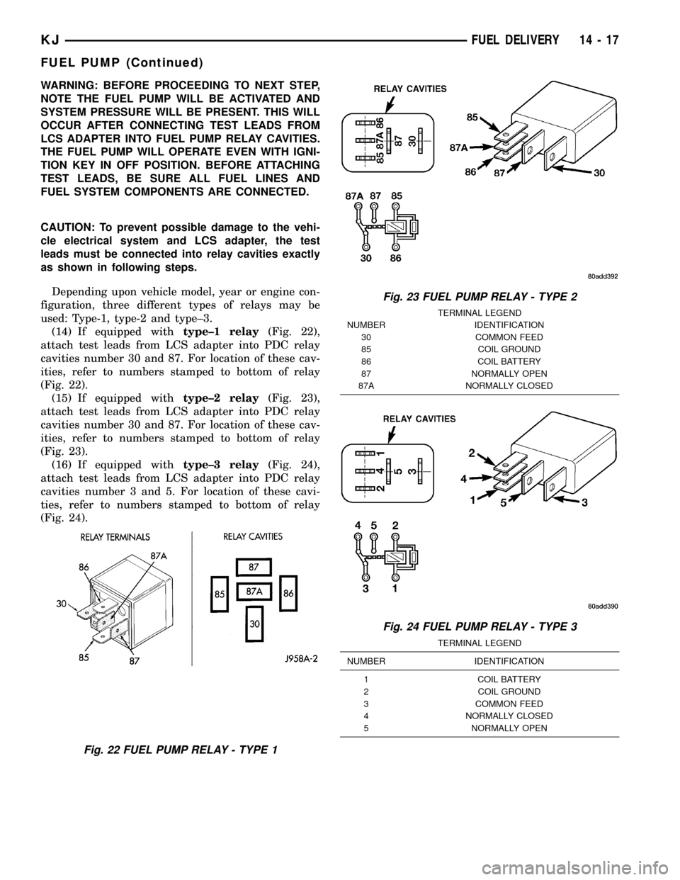
(14) If equipped withtype±1 relay(Fig. 22),
attach test leads from LCS adapter into PDC relay
cavities number 30 and 87. For location of these cav-
ities, refer to numbers stamped to bottom of relay
(Fig. 22).
(15) If equipped withtype±2 relay(Fig. 23),
attach test leads from LCS adapter into PDC relay
cavities number 30 and 87. For location of these cav-
ities, refer to numbers stamped to bottom of relay
(Fig. 23).
(16) If equipped withtype±3 relay(Fig. 24),
attach test leads from LCS adapter into PDC relay
cavities number 3 and 5. For location of these cavi-
ties, refer to numbers stamped to bottom of relay
(Fig. 24).
Fig. 22 FUEL PUMP RELAY - TYPE 1
Fig. 23 FUEL PUMP RELAY - TYPE 2
TERMINAL LEGEND
NUMBER IDENTIFICATION
30 COMMON FEED
85 COIL GROUND
86 COIL BATTERY
87 NORMALLY OPEN
87A NORMALLY CLOSED
Fig. 24 FUEL PUMP RELAY - TYPE 3
TERMINAL LEGEND
NUMBER IDENTIFICATION
1 COIL BATTERY
2 COIL GROUND
3 COMMON FEED
4 NORMALLY CLOSED
5 NORMALLY OPEN
KJFUEL DELIVERY 14 - 17
FUEL PUMP (Continued)
Page 1416 of 1803

REMOVAL
(1) Remove fuel rail. Refer to Fuel Injector Rail
Removal.
(2) Disconnect clip(s) that retain fuel injector(s) to
fuel rail (Fig. 10).
INSTALLATION
(1) Install fuel injector(s) into fuel rail assembly
and install retaining clip(s).
(2) If same injector(s) is being reinstalled, install
new o-ring(s).
(3) Apply a small amount of clean engine oil to
each injector o-ring. This will aid in installation.
(4) Install fuel rail. Refer to Fuel Rail Installation.
(5) Start engine and check for fuel leaks.
FUEL PUMP RELAY
DESCRIPTION
The 5±pin, 12±volt, fuel pump relay is located in
the Power Distribution Center (PDC). Refer to the
label on the PDC cover for relay location.
OPERATION
The Powertrain Control Module (PCM) energizes
the electric fuel pump through the fuel pump relay.
The fuel pump relay is energized by first applying
battery voltage to it when the ignition key is turnedON, and then applying a ground signal to the relay
from the PCM.
Whenever the ignition key is turned ON, the elec-
tric fuel pump will operate. But, the PCM will shut-
down the ground circuit to the fuel pump relay in
approximately 1±3 seconds unless the engine is oper-
ating or the starter motor is engaged.
DIAGNOSIS AND TESTING - FUEL PUMP
RELAY
For procedures, refer to ASD Relay Diagnosis and
Testing in the Ignition section.
REMOVAL
The fuel pump relay is located in the Power Distri-
bution Center (PDC) (Fig. 11). Refer to label on PDC
cover for relay location.
(1) Remove PDC cover.
(2) Remove relay from PDC.
(3) Check condition of relay terminals and PDC
connector terminals for damage or corrosion. Repair
if necessary before installing relay.
(4) Check for pin height (pin height should be the
same for all terminals within the PDC connector).
Repair if necessary before installing relay.
INSTALLATION
The fuel pump relay is located in the Power Distri-
bution Center (PDC). Refer to label on PDC cover for
relay location.
(1) Install relay to PDC.
(2) Install cover to PDC.
Fig. 10 INJECTOR RETAINING CLIP
1 - PLIERS
2 - INJECTOR CLIP
3 - FUEL INJECTOR
4 - FUEL RAIL - TYPICAL
Fig. 11 POWER DISTRIBUTION CENTER (PDC)
1 - BATTERY
2 - PDC
3 - PDC COVER
14 - 34 FUEL INJECTIONKJ
FUEL INJECTOR (Continued)