2002 JEEP LIBERTY Body
[x] Cancel search: BodyPage 1624 of 1803
HEADLINER
REMOVAL
(1) Remove the a-pillar trim. (Refer to 23 - BODY/
INTERIOR/A-PILLAR TRIM AND GRAB HANDLE -
REMOVAL)
(2) Remove the visors. (Refer to 23 - BODY/INTE-
RIOR/SUN VISOR - REMOVAL)
(3) Remove the sun visor support. (Refer to 23 -
BODY/INTERIOR/SUN VISOR SUPPORT -
REMOVAL)
(4) Remove the overhead console. (Refer to 8 -
ELECTRICAL/OVERHEAD CONSOLE - REMOVAL)
(5) Cut rear washer hose at the mark about half-
way up the a-pillar.
(6) Remove the upper b-pillar trim. (Refer to 23 -
BODY/INTERIOR/B-PILLAR UPPER TRIM -
REMOVAL)
(7) Remove the assist handles. (Refer to 23 -
BODY/INTERIOR/ASSIST HANDLE - REMOVAL)
(8) Remove the quarter trim. (Refer to 23 - BODY/
INTERIOR/QUARTER TRIM PANEL - REMOVAL)
(9) Disconnect the electrical connector along the
left d-pillar and remove the ground wire.
(10) Remove the dome light in the rear.
(11) Remove the sunroof opening trim lace, if
equipped. (Refer to 23 - BODY/SUNROOF/OPENING
TRIM LACE - REMOVAL)(12) Remove the rear washer nozzle.
(13) Remove the headliner.
INSTALLATION
(1) Install the headliner.
(2) Install the assist handles. (Refer to 23 - BODY/
INTERIOR/ASSIST HANDLE - INSTALLATION)
(3) Install the visors. (Refer to 23 - BODY/INTERI-
OR/SUN VISOR - INSTALLATION)
(4) Install the visor supports. (Refer to 23 - BODY/
INTERIOR/SUN VISOR SUPPORT - INSTALLA-
TION)
(5) Install the overhead console. (Refer to 8 -
ELECTRICAL/OVERHEAD CONSOLE - INSTALLA-
TION)
(6) Connect the rear washer hose, previously cut,
with a hose junction.
(7) Install the a-pillar trim and grab handles.
(Refer to 23 - BODY/INTERIOR/A-PILLAR TRIM -
INSTALLATION)
(8) Install the upper b-pillar trim. (Refer to 23 -
BODY/INTERIOR/B-PILLAR UPPER TRIM -
INSTALLATION)
(9) Install the rear washer nozzle.
(10) Connect the electrical connector and ground
wire at the left d-pillar.
(11) Install the quarter trim panels. (Refer to 23 -
BODY/INTERIOR/QUARTER TRIM PANEL -
INSTALLATION)
(12) Install the rear dome light.
(13) Install the sunroof opening trim lace, if
equipped. (Refer to 23 - BODY/SUNROOF/OPENING
TRIM LACE - INSTALLATION)
QUARTER TRIM PANEL
REMOVAL
(1) Using a trim stick C-4755 or equivalent,
remove the rear header trim.
(2) Using a trim stick C-4755 or equivalent,
remove the rear sill plate.
(3) Remove the hook pin type connector.
(4) Fold down the rear seat.
(5) Remove the seat belt anchor and pivot. (Refer
to 8 - ELECTRICAL/RESTRAINTS/SEAT BELT &
RETRACTOR - REMOVAL)
(6) Remove the belt access panel. (Fig. 4)
(7) Remove the storage cover.
(8) Disconnect the 12v power supply electrical con-
nector, if equipped.
INSTALLATION
(1) Position the 12v power supply electrical con-
nector, if equipped.
(2) Install the storage cover.
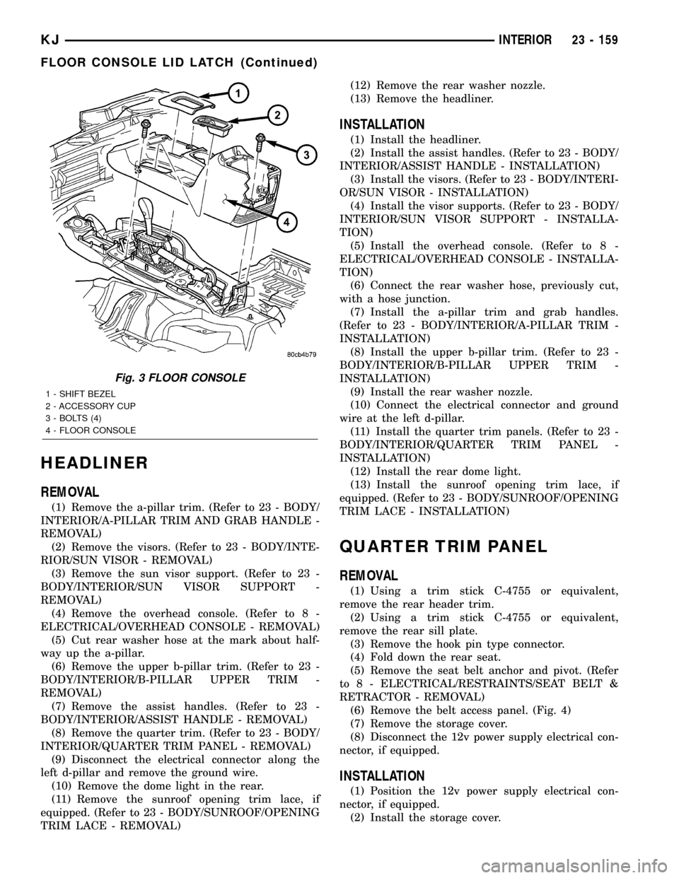
Fig. 3 FLOOR CONSOLE
1 - SHIFT BEZEL
2 - ACCESSORY CUP
3 - BOLTS (4)
4 - FLOOR CONSOLE
KJINTERIOR 23 - 159
FLOOR CONSOLE LID LATCH (Continued)
Page 1628 of 1803
CAUTION: Do not use abrasive chemicals or com-
pounds on painted surfaces. Damage to finish can
result.
Do not use harsh alkaline based cleaning solvents
on painted surfaces. Damage to finish or color can
result.
PAINT TOUCH-UP
DESCRIPTION
When a painted metal surface has been scratched
or chipped, it should be touched-up as soon as possi-
ble to avoid corrosion. For best results, use Mopart
Scratch Filler/Primer, Touch-Up Paints and Clear Top
Coat. Refer to Introduction group of this manual for
Body Code Plate information.
WARNING: USE AN OSHA APPROVED BREATHING
FILTER WHEN SPRAYING PAINT OR SOLVENTS IN
A CONFINED AREA. PERSONAL INJURY CAN
RESULT.
OPERATION
(1) Scrape loose paint and corrosion from inside
scratch or chip.
(2) Clean affected area with MopartTar/Road Oil
Remover, and allow to dry.
(3) Fill the inside of the scratch or chip with a coat
of filler/primer. Do not overlap primer onto good sur-
face finish. The applicator brush should be wet
enough to puddle-fill the defect without running. Do
not stroke brush applicator on body surface. Allow
the filler/primer to dry hard.
(4) Cover the filler/primer with color touch-up
paint. Do not overlap touch-up color onto the originalcolor coat around the scratch or chip. Butt the new
color to the original color, if possible. Do not stroke
applicator brush on body surface. Allow touch-up
paint to dry hard.
(5) On vehicles without clear coat, the touch-up
color can be lightly finesse sanded (1500 grit) and
polished with rubbing compound.
(6) On vehicles with clear coat, apply clear top coat
to touch-up paint with the same technique as
described in Step 4. Allow clear top coat to dry hard.
If desired, Step 5 can be performed on clear top coat.
WARNING: AVOID PROLONGED SKIN CONTACT
WITH PETROLEUM OR ALCOHOL ± BASED CLEAN-
ING SOLVENTS. PERSONAL INJURY CAN RESULT.
AVOID PROLONGED SKIN CONTACT WITH PETRO-
LEUM OR ALCOHOL ± BASED CLEANING SOL-
VENTS. PERSONAL INJURY CAN RESULT.
FINESSE SANDING/BUFFING &
POLISHING
DESCRIPTION
Minor acid etching, orange peel, or smudging in
clear coat or single-stage finishes can be reduced
with light finesse sanding, hand buffing, and polish-
ing.If the finish has been finesse sanded in the
past, it cannot be repeated. Finesse sanding
operation should be performed by a trained
automotive paint technician.
CAUTION: Do not remove clear coat finish, if
equipped. Base coat paint must retain clear coat for
durability.
KJPAINT 23 - 163
BASE COAT/CLEAR COAT FINISH (Continued)
Page 1629 of 1803
SEATS
TABLE OF CONTENTS
page page
HEADREST
REMOVAL............................164
INSTALLATION........................164
HEADREST SLEEVE
REMOVAL............................164
INSTALLATION........................164
SEAT - FRONT
REMOVAL............................165
INSTALLATION........................165
SEAT BACK - FRONT
REMOVAL............................166
INSTALLATION........................166
SEAT BACK RECLINER - FRONT
REMOVAL............................166
INSTALLATION........................166
SEAT BACK COVER - FRONT
REMOVAL............................166
INSTALLATION........................167
SEAT BACK CUSHION - FRONT
REMOVAL............................167
INSTALLATION........................167
SEAT CUSHION - FRONT
REMOVAL............................167
INSTALLATION........................167
SEAT CUSHION COVER - FRONT
REMOVAL............................167
INSTALLATION........................167
SEAT CUSHION SIDE SHIELDS
REMOVAL............................167
INSTALLATION........................167MANUAL SEAT RISER
REMOVAL............................167
INSTALLATION........................168
SEAT TRACK
REMOVAL............................168
INSTALLATION........................168
SEAT - REAR
REMOVAL............................168
INSTALLATION........................168
SEAT BACK - REAR
REMOVAL............................168
INSTALLATION........................168
SEAT BACK COVER - REAR
REMOVAL............................169
INSTALLATION........................169
SEAT BACK CUSHION - REAR
REMOVAL............................170
INSTALLATION........................170
FOLDING REAR SEAT BACK LATCH / LOCK
REMOVAL............................170
INSTALLATION........................170
REAR SEAT BACK LATCH STRIKER
REMOVAL............................170
INSTALLATION........................171
SEAT BACK FRAME - REAR
REMOVAL............................171
INSTALLATION........................171
SEAT CUSHION - REAR
REMOVAL............................171
INSTALLATION........................171
HEADREST
REMOVAL
(1) Depress head restraint release button and lift
head restraint to full up position.
(2) Using a small flat blade, depress tab on right
side head restraint release button and using your
hand, simultaneously press tab on left side head
restraint release button and pull head restraint up to
separate from seat back.
INSTALLATION
(1) Position head restraint in seat back, press tab
on left side head restraint release button and push
down head restraint to secure.
HEADREST SLEEVE
REMOVAL
(1) Remove the headrest. (Refer to 23 - BODY/
SEATS/HEADREST - REMOVAL)
(2) Remove the headrest sleeve cover.
(3) Rotate head restraint sleeve 1/4 turn counter-
clockwise to release retaining tab.
(4) Pull sleeve from seat back frame.
INSTALLATION
(1) Position sleeve in seat back frame.
(2) Rotate head restraint sleeve 1/4 turn clockwise
to engage retaining tab.
(3) Install the headrest sleeve cover.
(4) Install the headrest. (Refer to 23 - BODY/
SEATS/HEADREST - INSTALLATION)
23 - 164 SEATSKJ
Page 1631 of 1803
(4) Slide the seat to the forward position and
install the rear bolt and nut.
(5) Tighten the fasteners to 43 N´m (32 ft. lbs.).
(6) Install the seat belt anchor and bolt. (Refer to
8 - ELECTRICAL/RESTRAINTS/SEAT BELT &
RETRACTOR - INSTALLATION)
SEAT BACK - FRONT
REMOVAL
(1) Remove the seat. (Refer to 23 - BODY/SEATS/
SEAT - FRONT - REMOVAL)
(2) Remove the seat cushion side shields. (Refer to
23 - BODY/SEATS/SEAT CUSHION SIDE SHIELDS
- REMOVAL)
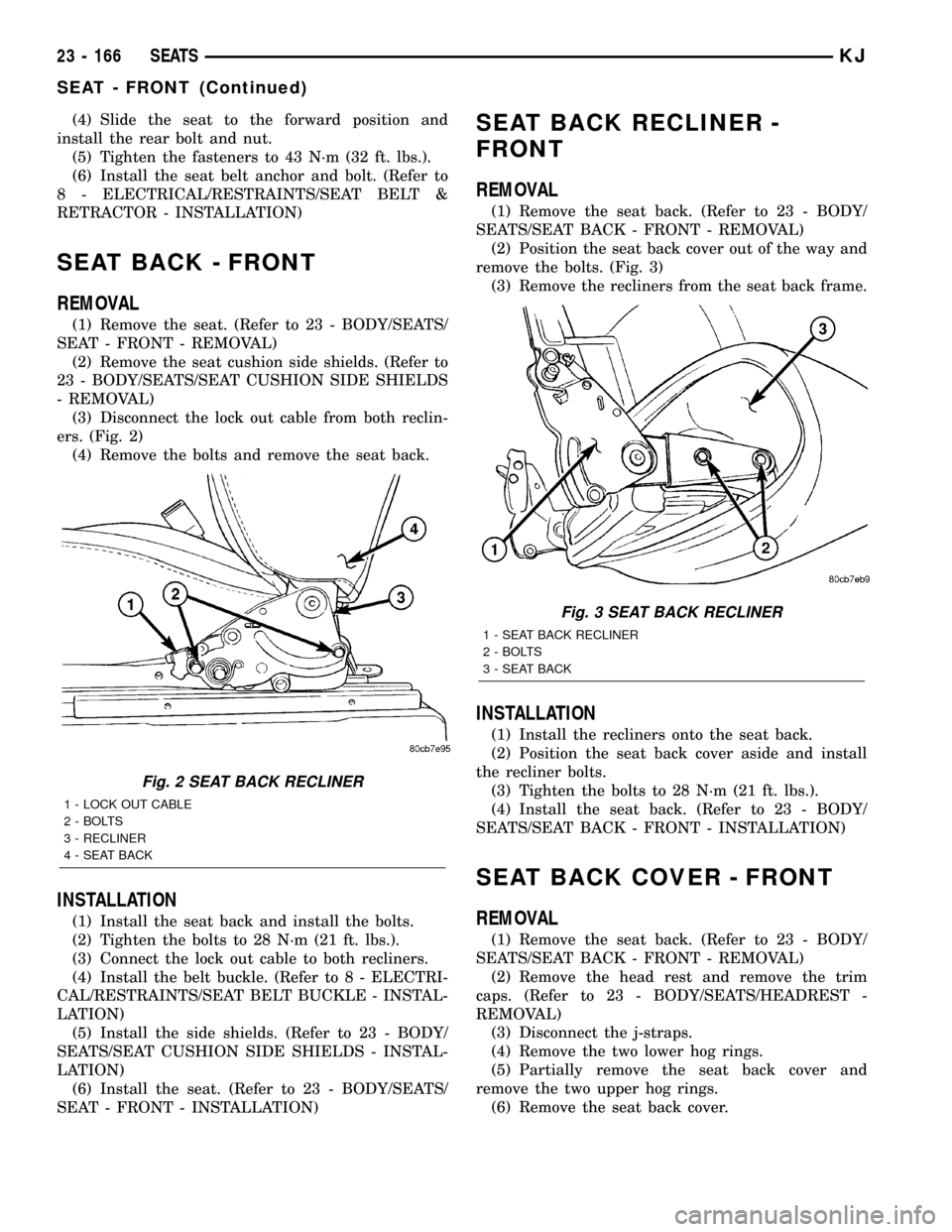
(3) Disconnect the lock out cable from both reclin-
ers. (Fig. 2)
(4) Remove the bolts and remove the seat back.
INSTALLATION
(1) Install the seat back and install the bolts.
(2) Tighten the bolts to 28 N´m (21 ft. lbs.).
(3) Connect the lock out cable to both recliners.
(4) Install the belt buckle. (Refer to 8 - ELECTRI-
CAL/RESTRAINTS/SEAT BELT BUCKLE - INSTAL-
LATION)
(5) Install the side shields. (Refer to 23 - BODY/
SEATS/SEAT CUSHION SIDE SHIELDS - INSTAL-
LATION)
(6) Install the seat. (Refer to 23 - BODY/SEATS/
SEAT - FRONT - INSTALLATION)
SEAT BACK RECLINER -
FRONT
REMOVAL
(1) Remove the seat back. (Refer to 23 - BODY/
SEATS/SEAT BACK - FRONT - REMOVAL)
(2) Position the seat back cover out of the way and
remove the bolts. (Fig. 3)
(3) Remove the recliners from the seat back frame.
INSTALLATION
(1) Install the recliners onto the seat back.
(2) Position the seat back cover aside and install
the recliner bolts.
(3) Tighten the bolts to 28 N´m (21 ft. lbs.).
(4) Install the seat back. (Refer to 23 - BODY/
SEATS/SEAT BACK - FRONT - INSTALLATION)
SEAT BACK COVER - FRONT
REMOVAL
(1) Remove the seat back. (Refer to 23 - BODY/
SEATS/SEAT BACK - FRONT - REMOVAL)
(2) Remove the head rest and remove the trim
caps. (Refer to 23 - BODY/SEATS/HEADREST -
REMOVAL)
(3) Disconnect the j-straps.
(4) Remove the two lower hog rings.
(5) Partially remove the seat back cover and
remove the two upper hog rings.
(6) Remove the seat back cover.
Fig. 2 SEAT BACK RECLINER
1 - LOCK OUT CABLE
2 - BOLTS
3 - RECLINER
4 - SEAT BACK
Fig. 3 SEAT BACK RECLINER
1 - SEAT BACK RECLINER
2 - BOLTS
3 - SEAT BACK
23 - 166 SEATSKJ
SEAT - FRONT (Continued)
Page 1632 of 1803
INSTALLATION
(1) Partially install the seat back cover and
replace the two top hog rings.
(2) Pull cover down and replace the two lower hog
rings.
(3) Connect the j-straps.
(4) Install trim caps and the head rest. (Refer to
23 - BODY/SEATS/HEADREST - INSTALLATION)
(5) Install the seat back. (Refer to 23 - BODY/
SEATS/SEAT BACK - FRONT - INSTALLATION)
SEAT BACK CUSHION - FRONT
REMOVAL
(1) Remove the seat back cover. (Refer to 23 -
BODY/SEATS/SEAT BACK COVER - FRONT -
REMOVAL)
(2) Separate the cushion from the seat back frame.
INSTALLATION
(1) Position the cushion onto the seat back frame.
(2) Install the seat back cover. (Refer to 23 -
BODY/SEATS/SEAT BACK COVER - FRONT -
INSTALLATION)
SEAT CUSHION - FRONT
REMOVAL
(1) Remove the seat back. (Refer to 23 - BODY/
SEATS/SEAT BACK - FRONT - REMOVAL)
(2) Remove the two outer front track bolts and
remove the track.
INSTALLATION
(1) Install the seat cushion onto the seat track
assembly and install the front two bolts.
(2) Tighten the bolts to 28 N´m (21 ft. lbs.).
(3) Install the seat back. (Refer to 23 - BODY/
SEATS/SEAT BACK - FRONT - INSTALLATION)
SEAT CUSHION COVER -
FRONT
REMOVAL
(1) Remove the seat cushion. (Refer to 23 - BODY/
SEATS/SEAT CUSHION - FRONT - REMOVAL)
(2) Disconnect the j-straps.
(3) Remove the hog rings and remove the cushion
cover.
INSTALLATION
(1) Position the seat cushion cover and install new
hog rings.
(2) Connect the j-straps.
(3) Install the seat cushion. (Refer to 23 - BODY/
SEATS/SEAT CUSHION - FRONT - INSTALLA-
TION)
SEAT CUSHION SIDE SHIELDS
REMOVAL
(1) Remove the screw and remove the recliner han-
dle.
(2) Remove the screws and remove the seat side
shields.
INSTALLATION
(1) Install the shields and install the screws.
(2) Install the recliner handle and install the
screw.
MANUAL SEAT RISER
REMOVAL
(1) Remove the seat. (Refer to 23 - BODY/SEATS/
SEAT - FRONT - REMOVAL)
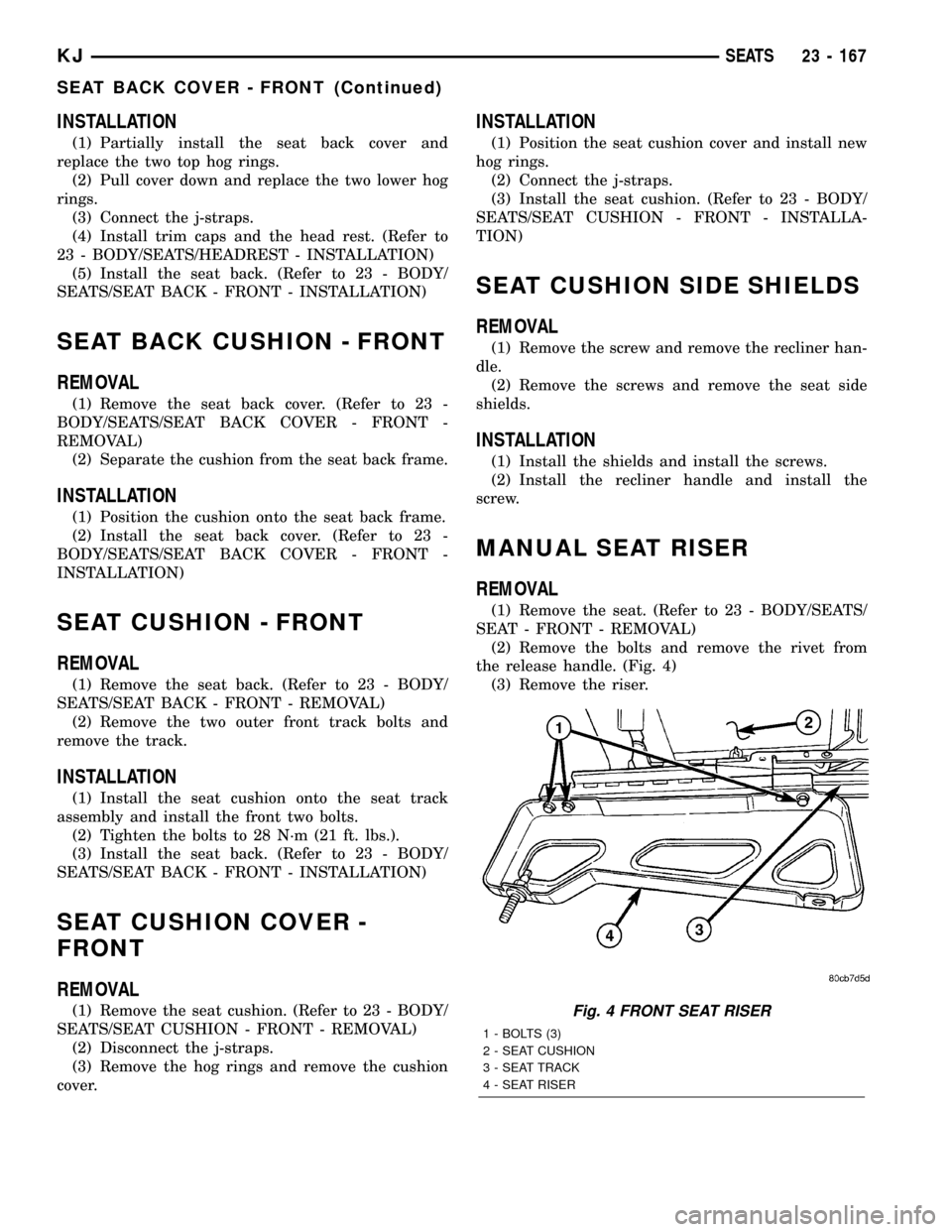
(2) Remove the bolts and remove the rivet from
the release handle. (Fig. 4)
(3) Remove the riser.
Fig. 4 FRONT SEAT RISER
1 - BOLTS (3)
2 - SEAT CUSHION
3 - SEAT TRACK
4 - SEAT RISER
KJSEATS 23 - 167
SEAT BACK COVER - FRONT (Continued)
Page 1633 of 1803
INSTALLATION
(1) Install the seat riser and install the bolts.
(2) Tighten the bolts to 28 N´m (21 ft. lbs.).
(3) Install a new release handle rivet.
(4) Install the seat. (Refer to 23 - BODY/SEATS/
SEAT - FRONT - INSTALLATION)
SEAT TRACK
REMOVAL
(1) Remove the seat back. (Refer to 23 - BODY/
SEATS/SEAT BACK - FRONT - REMOVAL)
(2) Remove the outer riser. (Refer to 23 - BODY/
SEATS/SEAT RISER - REMOVAL)
(3) Remove the front outer bolts and remove the
tracks.
INSTALLATION
(1) Install the seat track onto the seat cushion and
install the front outer bolts.
(2) Tighten the bolts to 28 N´m (21 ft. lbs.).
(3) Install the seat riser. (Refer to 23 - BODY/
SEATS/SEAT RISER - INSTALLATION)
(4) Install the seat back. (Refer to 23 - BODY/
SEATS/SEAT BACK - FRONT - INSTALLATION)
SEAT - REAR
REMOVAL
(1) Remove the outer seat belt anchors. (Refer to 8
- ELECTRICAL/RESTRAINTS/SEAT BELT &
RETRACTOR - REMOVAL)
(2) Remove the inner seat belt buckles. (Refer to 8
- ELECTRICAL/RESTRAINTS/SEAT BELT BUCKLE
- REMOVAL)
(3) Remove the center seat belt anchor. (Refer to 8
- ELECTRICAL/RESTRAINTS/SEAT BELT &
RETRACTOR - REMOVAL)
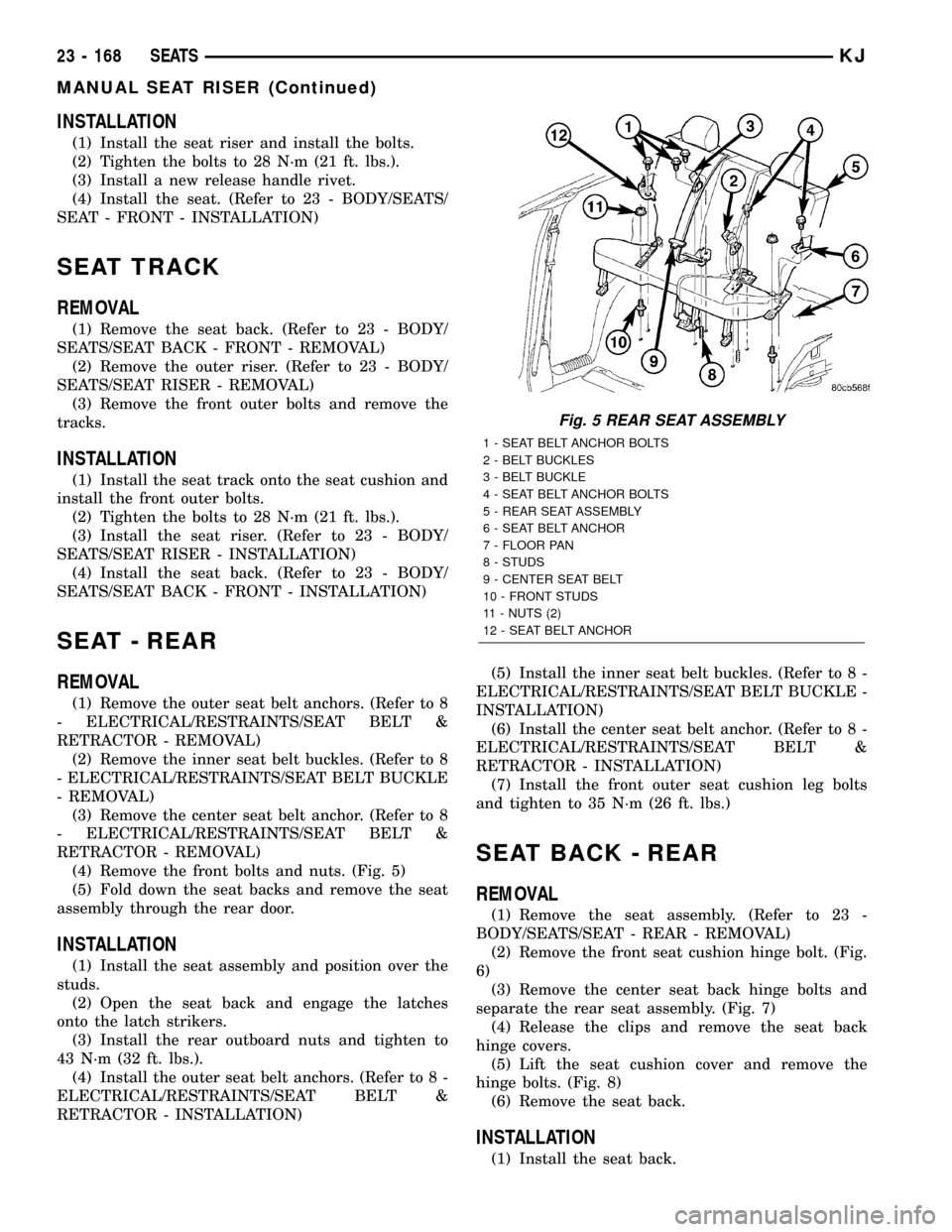
(4) Remove the front bolts and nuts. (Fig. 5)
(5) Fold down the seat backs and remove the seat
assembly through the rear door.
INSTALLATION
(1) Install the seat assembly and position over the
studs.
(2) Open the seat back and engage the latches
onto the latch strikers.
(3) Install the rear outboard nuts and tighten to
43 N´m (32 ft. lbs.).
(4) Install the outer seat belt anchors. (Refer to 8 -
ELECTRICAL/RESTRAINTS/SEAT BELT &
RETRACTOR - INSTALLATION)(5) Install the inner seat belt buckles. (Refer to 8 -
ELECTRICAL/RESTRAINTS/SEAT BELT BUCKLE -
INSTALLATION)
(6) Install the center seat belt anchor. (Refer to 8 -
ELECTRICAL/RESTRAINTS/SEAT BELT &
RETRACTOR - INSTALLATION)
(7) Install the front outer seat cushion leg bolts
and tighten to 35 N´m (26 ft. lbs.)
SEAT BACK - REAR
REMOVAL
(1) Remove the seat assembly. (Refer to 23 -
BODY/SEATS/SEAT - REAR - REMOVAL)
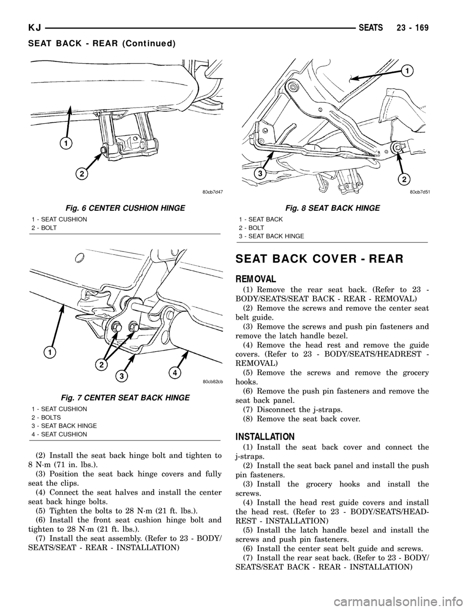
(2) Remove the front seat cushion hinge bolt. (Fig.
6)
(3) Remove the center seat back hinge bolts and
separate the rear seat assembly. (Fig. 7)
(4) Release the clips and remove the seat back
hinge covers.
(5) Lift the seat cushion cover and remove the
hinge bolts. (Fig. 8)
(6) Remove the seat back.
INSTALLATION
(1) Install the seat back.
Fig. 5 REAR SEAT ASSEMBLY
1 - SEAT BELT ANCHOR BOLTS
2 - BELT BUCKLES
3 - BELT BUCKLE
4 - SEAT BELT ANCHOR BOLTS
5 - REAR SEAT ASSEMBLY
6 - SEAT BELT ANCHOR
7 - FLOOR PAN
8 - STUDS
9 - CENTER SEAT BELT
10 - FRONT STUDS
11 - NUTS (2)
12 - SEAT BELT ANCHOR
23 - 168 SEATSKJ
MANUAL SEAT RISER (Continued)
Page 1634 of 1803
(2) Install the seat back hinge bolt and tighten to
8 N´m (71 in. lbs.).
(3) Position the seat back hinge covers and fully
seat the clips.
(4) Connect the seat halves and install the center
seat back hinge bolts.
(5) Tighten the bolts to 28 N´m (21 ft. lbs.).
(6) Install the front seat cushion hinge bolt and
tighten to 28 N´m (21 ft. lbs.).
(7) Install the seat assembly. (Refer to 23 - BODY/
SEATS/SEAT - REAR - INSTALLATION)
SEAT BACK COVER - REAR
REMOVAL
(1) Remove the rear seat back. (Refer to 23 -
BODY/SEATS/SEAT BACK - REAR - REMOVAL)
(2) Remove the screws and remove the center seat
belt guide.
(3) Remove the screws and push pin fasteners and
remove the latch handle bezel.
(4) Remove the head rest and remove the guide
covers. (Refer to 23 - BODY/SEATS/HEADREST -
REMOVAL)
(5) Remove the screws and remove the grocery
hooks.
(6) Remove the push pin fasteners and remove the
seat back panel.
(7) Disconnect the j-straps.
(8) Remove the seat back cover.
INSTALLATION
(1) Install the seat back cover and connect the
j-straps.
(2) Install the seat back panel and install the push
pin fasteners.
(3) Install the grocery hooks and install the
screws.
(4) Install the head rest guide covers and install
the head rest. (Refer to 23 - BODY/SEATS/HEAD-
REST - INSTALLATION)
(5) Install the latch handle bezel and install the
screws and push pin fasteners.
(6) Install the center seat belt guide and screws.
(7) Install the rear seat back. (Refer to 23 - BODY/
SEATS/SEAT BACK - REAR - INSTALLATION)
Fig. 6 CENTER CUSHION HINGE
1 - SEAT CUSHION
2 - BOLT
Fig. 7 CENTER SEAT BACK HINGE
1 - SEAT CUSHION
2 - BOLTS
3 - SEAT BACK HINGE
4 - SEAT CUSHION
Fig. 8 SEAT BACK HINGE
1 - SEAT BACK
2 - BOLT
3 - SEAT BACK HINGE
KJSEATS 23 - 169
SEAT BACK - REAR (Continued)
Page 1635 of 1803
SEAT BACK CUSHION - REAR
REMOVAL
(1) Remove the seat back cover. (Refer to 23 -
BODY/SEATS/SEAT BACK COVER - REAR -
REMOVAL)
(2) Separate the cushion from the seat back frame.
INSTALLATION
(1) Position the seat back cushion onto the seat
back frame.
(2) Install the seat back cover. (Refer to 23 -
BODY/SEATS/SEAT BACK COVER - REAR -
INSTALLATION)
FOLDING REAR SEAT BACK
LATCH / LOCK
REMOVAL
(1) Remove the rear seat back cushion. (Refer to
23 - BODY/SEATS/SEAT BACK CUSHION / COVER
- REAR - REMOVAL)
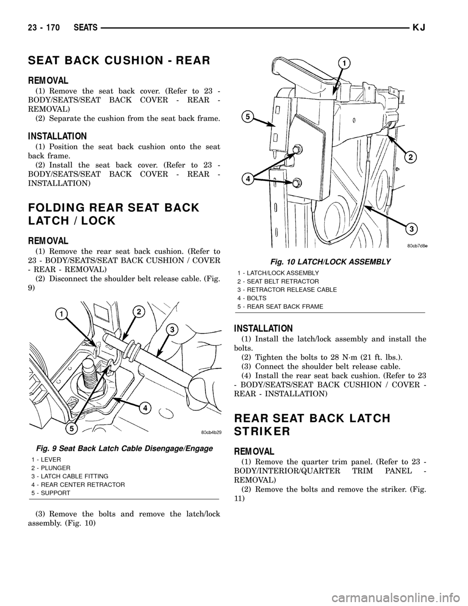
(2) Disconnect the shoulder belt release cable. (Fig.
9)
(3) Remove the bolts and remove the latch/lock
assembly. (Fig. 10)
INSTALLATION
(1) Install the latch/lock assembly and install the
bolts.
(2) Tighten the bolts to 28 N´m (21 ft. lbs.).
(3) Connect the shoulder belt release cable.
(4) Install the rear seat back cushion. (Refer to 23
- BODY/SEATS/SEAT BACK CUSHION / COVER -
REAR - INSTALLATION)
REAR SEAT BACK LATCH
STRIKER
REMOVAL
(1) Remove the quarter trim panel. (Refer to 23 -
BODY/INTERIOR/QUARTER TRIM PANEL -
REMOVAL)
(2) Remove the bolts and remove the striker. (Fig.
11 )
Fig. 9 Seat Back Latch Cable Disengage/Engage
1 - LEVER
2 - PLUNGER
3 - LATCH CABLE FITTING
4 - REAR CENTER RETRACTOR
5 - SUPPORT
Fig. 10 LATCH/LOCK ASSEMBLY
1 - LATCH/LOCK ASSEMBLY
2 - SEAT BELT RETRACTOR
3 - RETRACTOR RELEASE CABLE
4 - BOLTS
5 - REAR SEAT BACK FRAME
23 - 170 SEATSKJ