2002 JEEP LIBERTY suspension
[x] Cancel search: suspensionPage 568 of 1803

HEADLAMP ALIGNMENT SCREEN PREPARATION
Prepare an alignment screen as illustrated.
(1) Position the vehicle on a level surface perpen-
dicular to a flat wall 7.62 meters (25 feet) away from
the front of the headlamp lens for North American
vehicles, or 10.0 meters (32.81 feet) away from the
front of the headlamp lens for Rest-Of-World vehicles
(Fig. 43). If necessary, tape a line on the floor at the
appropriate distance away from and parallel to the
wall.
(2) Measure up on the wall 1.27 meters (5 feet)
from the floor and tape a vertical line on the align-
ment screen at the centerline of the vehicle. Sight
along the centerline of the vehicle (from the rear of
the vehicle forward) to verify the accuracy of the cen-
terline placement.
(3) Rock the vehicle from side-to-side three times
to allow the suspension to stabilize, then jounce the
front suspension three times by pushing downward
on the front bumper and releasing. Measure the dis-
tance from the center of the headlamp lens to the
floor. Transfer this measurement to the alignment
screen and tape a horizontal line on the wall at this
mark. This line will be used for up-and-down adjust-
ment reference.(4) Measure the distance from the centerline of the
vehicle to the center of each headlamp being aligned.
Transfer these measurements to the alignment
screen and tape a vertical line this distance to each
side of the vehicle centerline. These lines will be used
for left/right reference.
HEADLAMP ADJUSTMENT
A properly aligned headlamp will project a pattern
on the alignment screen from just below horizontal to
75 millimeters (3 inches) below the headlamp center-
line for vehicles in North America, or from just below
horizontal to 125 millimeters (5 inches) below the
headlamp horizontal centerline for vehicles in Rest-
Of-World.
(1) Vehicles for all markets except Japan should
have the headlamp low beams selected with the dim-
mer (multi-function) switch during the adjustment
procedure. Vehicles for the Japanese market should
have the headlamp high beams selected.
(2) Cover the lens of the headlamp that is not
being adjusted.
(3) Turn the adjusting screw (Fig. 44) until the top
edge of the beam intensity pattern is positioned from
just below horizontal to 75 millimeters (3 inches)
Fig. 43 Headlamp Alignment Screen - Typical
1 - CENTER OF VEHICLE TO CENTER OF HEADLAMP LENS
2 - FLOOR TO CENTER OF HEADLAMP LENS
3 - 7.62 METERS (25 FEET) NORTH AMERICA/10.0 METERS
(32.81 FEET) REST-OF-WORLD4 - FRONT OF HEADLAMP
5 - VEHICLE CENTERLINE
KJLAMPS8Ls-43
HEADLAMP UNIT (Continued)
Page 752 of 1803

TERMINOLOGY
This is a list of terms and definitions used in the
wiring diagrams.
LHD .................Left Hand Drive Vehicles
RHD................Right Hand Drive Vehicles
ATX . . Automatic Transmissions-Front Wheel Drive
MTX....Manual Transmissions-Front Wheel Drive
AT ....Automatic Transmissions-Rear Wheel Drive
MT .....Manual Transmissions-Rear Wheel Drive
SOHC...........Single Over Head Cam Engine
DOHC..........Double Over Head Cam Engine
Built-Up-Export........ Vehicles Built For Sale In
Markets Other Than North America
Except-Built-Up-Export . . Vehicles Built For Sale In
North America
DESCRIPTION - CIRCUIT INFORMATION
Each wire shown in the diagrams contains a code
which identifies the main circuit, part of the main
circuit, gage of wire, and color (Fig. 4).
WIRE COLOR CODE CHART
COLOR CODE COLOR
BL BLUE
BK BLACK
BR BROWN
DB DARK BLUE
DG DARK GREEN
GY GRAY
LB LIGHT BLUE
LG LIGHT GREEN
COLOR CODE COLOR
OR ORANGE
PK PINK
RD RED
TN TAN
VT VIOLET
WT WHITE
YL YELLOW
* WITH TRACER
DESCRIPTION - CIRCUIT FUNCTIONS
All circuits in the diagrams use an alpha/numeric
code to identify the wire and it's function. To identify
which circuit code applies to a system, refer to the
Circuit Identification Code Chart. This chart shows
the main circuits only and does not show the second-
ary codes that may apply to some models.
CIRCUIT IDENTIFICATION CODE CHART
CIRCUIT FUNCTION
A BATTERY FEED
B BRAKE CONTROLS
C CLIMATE CONTROLS
D DIAGNOSTIC CIRCUITS
E DIMMING ILLUMINATION
CIRCUITS
F FUSED CIRCUITS
G MONITORING CIRCUITS
(GAUGES)
H OPEN
I NOT USED
J OPEN
K POWERTRAIN CONTROL
MODULE
L EXTERIOR LIGHTING
M INTERIOR LIGHTING
N NOT USED
O NOT USED
P POWER OPTION (BATTERY
FEED)
Q POWER OPTIONS (IGNITION
FEED)
R PASSIVE RESTRAINT
S SUSPENSION/STEERING
T TRANSMISSION/TRANSAXLE/
TRANSFER CASE
Fig. 4 WIRE CODE IDENTIFICATION
1 - COLOR OF WIRE (LIGHT BLUE WITH YELLOW TRACER
2 - GAGE OF WIRE (18 GAGE)
3 - PART OF MAIN CIRCUIT (VARIES DEPENDING ON
EQUIPMENT)
4 - MAIN CIRCUIT IDENTIFICATION
KJ8W-01 WIRING DIAGRAM INFORMATION8Wa-01-5
WIRING DIAGRAM INFORMATION (Continued)
Page 1379 of 1803
SPECIFICATIONS - TORQUE
DESCRIPTION N´m Ft. Lbs. In. Lbs.
ENGINE CRADLE CROSSMEMBER INNER RAIL BOLTS 47 35 Ð
ENGINE CRADLE CROSSMEMBER MOUNTING BOLTS 122 90 Ð
ENGINE MOUNT THROUGH BOLTS/NUTS 88 65 Ð
FRONT SKID PLATE BOLTS 61 45 Ð
FRONT TOW HOOK NUTS/BOLT 61 45 Ð
FUEL TANK SKID PLATE 88 65 Ð
REAR CROSSMEMBER BOLTS 47 35 Ð
REAR TOW HOOK BOLTS 88 65 Ð
TRAILER HITCH BOLTS 88 65 Ð
TRANSFER CASE SKID PLATE BOLTS 34 25 Ð
TRANSMISSION MOUNT THROUGH BOLT/NUT 88 65 Ð
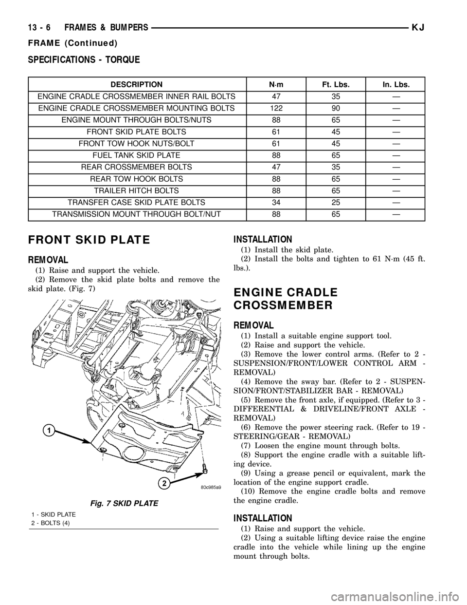
FRONT SKID PLATE
REMOVAL
(1) Raise and support the vehicle.
(2) Remove the skid plate bolts and remove the
skid plate. (Fig. 7)
INSTALLATION
(1) Install the skid plate.
(2) Install the bolts and tighten to 61 N´m (45 ft.
lbs.).
ENGINE CRADLE
CROSSMEMBER
REMOVAL
(1) Install a suitable engine support tool.
(2) Raise and support the vehicle.
(3) Remove the lower control arms. (Refer to 2 -
SUSPENSION/FRONT/LOWER CONTROL ARM -
REMOVAL)
(4) Remove the sway bar. (Refer to 2 - SUSPEN-
SION/FRONT/STABILIZER BAR - REMOVAL)
(5) Remove the front axle, if equipped. (Refer to 3 -
DIFFERENTIAL & DRIVELINE/FRONT AXLE -
REMOVAL)
(6) Remove the power steering rack. (Refer to 19 -
STEERING/GEAR - REMOVAL)
(7) Loosen the engine mount through bolts.
(8) Support the engine cradle with a suitable lift-
ing device.
(9) Using a grease pencil or equivalent, mark the
location of the engine support cradle.
(10) Remove the engine cradle bolts and remove
the engine cradle.
INSTALLATION
(1) Raise and support the vehicle.
(2) Using a suitable lifting device raise the engine
cradle into the vehicle while lining up the engine
mount through bolts.
Fig. 7 SKID PLATE
1 - SKID PLATE
2 - BOLTS (4)
13 - 6 FRAMES & BUMPERSKJ
FRAME (Continued)
Page 1380 of 1803
(3) Align the engine cradle to the marks made dur-
ing removal and install the mounting and inner rail
bolts.
(4) Tighten the mounting bolts to 122 N´m (90 ft.
lbs.).
(5) Tighten the inner rail bolts to 47 N´m (35 ft.
lbs.).
(6) Tighten the engine mount through bolts to 88
N´m (65 ft. lbs.).
(7) Install the power steering rack. (Refer to 19 -
STEERING/GEAR - INSTALLATION)
(8) Install the front axle, if equipped. (Refer to 3 -
DIFFERENTIAL & DRIVELINE/FRONT AXLE -
INSTALLATION)
(9) Install the stabilizer bar. (Refer to 2 - SUS-
PENSION/FRONT/STABILIZER BAR - INSTALLA-
TION)
(10) Install the lower control arms. (Refer to 2 -
SUSPENSION/FRONT/LOWER CONTROL ARM -
INSTALLATION)
(11) Lower the vehicle and remove the engine sup-
port tool.
TRANSFER CASE SKID PLATE
REMOVAL
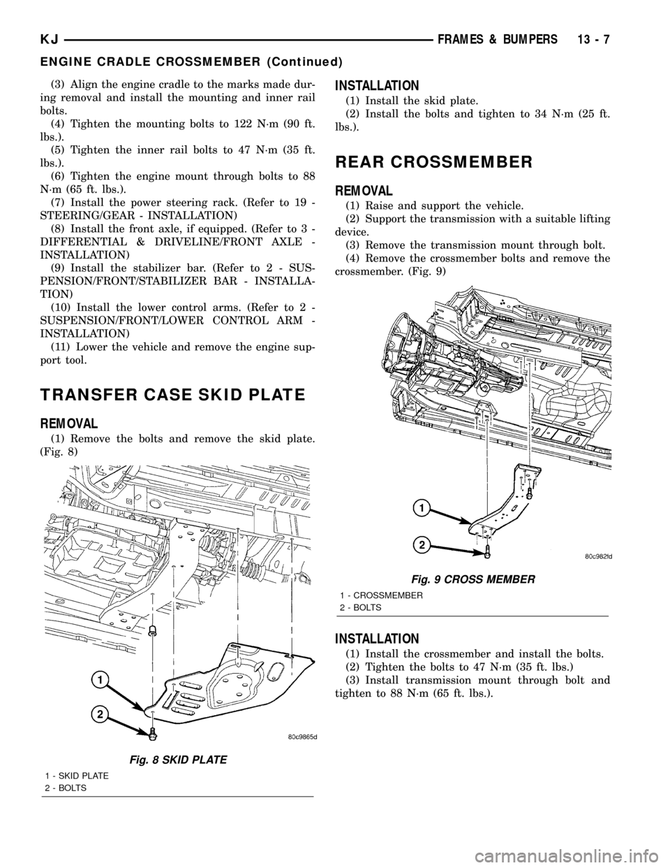
(1) Remove the bolts and remove the skid plate.
(Fig. 8)
INSTALLATION
(1) Install the skid plate.
(2) Install the bolts and tighten to 34 N´m (25 ft.
lbs.).
REAR CROSSMEMBER
REMOVAL
(1) Raise and support the vehicle.
(2) Support the transmission with a suitable lifting
device.
(3) Remove the transmission mount through bolt.
(4) Remove the crossmember bolts and remove the
crossmember. (Fig. 9)
INSTALLATION
(1) Install the crossmember and install the bolts.
(2) Tighten the bolts to 47 N´m (35 ft. lbs.)
(3) Install transmission mount through bolt and
tighten to 88 N´m (65 ft. lbs.).
Fig. 8 SKID PLATE
1 - SKID PLATE
2 - BOLTS
Fig. 9 CROSS MEMBER
1 - CROSSMEMBER
2 - BOLTS
KJFRAMES & BUMPERS 13 - 7
ENGINE CRADLE CROSSMEMBER (Continued)
Page 1431 of 1803
STEERING
TABLE OF CONTENTS
page page
STEERING
DESCRIPTION..........................1
OPERATION............................1
DIAGNOSIS AND TESTING
DIAGNOSIS AND TESTING - POWER
STEERING SYSTEM....................1DIAGNOSIS AND TESTING - POWER
STEERING FLOW AND PRESSURE........3
COLUMN...............................5
GEAR.................................13
LINKAGE..............................16
PUMP.................................17
STEERING
DESCRIPTION
Power steering systems consist of:
²Steering column & Intermediate Shaft
²Rack and pinion steering gear
²Belt driven hydraulic steering pump
²Pump pressure, supply and return hoses
²Oil Cooler
OPERATION
The steering column intermediate shaft attaches
the steering column to the gear pinion. The rotation
of the pinion moves the gear rack from side-to-side.
This lateral action of the rack pushes and pulls the
tie rods to change the direction of the front wheels.
Power assist is provided by an engine mounted
hydraulic pump. The pump supplies hydraulic fluid
to the steering gear. All vehicles are equipped with
an oil cooler.
DIAGNOSIS AND TESTING
DIAGNOSIS AND TESTING - POWER STEERING SYSTEM
STEERING NOISE
There is some noise in all power steering systems. One of the most common is a hissing sound evident at a
standstill/parking, or when the steering is at the end of it's travel. Hiss is a high frequency noise similar to that
of a water tap being closed slowly. The noise is present in all valves that have a high velocity fluid passing through
an orifice. There is no relationship between this noise and steering performance.
CONDITION POSSIBLE CAUSES CORRECTION
OBJECTIONAL HISS OR
WHISTLE1. Steering intermediate shaft to dash panel
seal.1. Check and repair seal at dash
panel.
2. Noisy valve in power steering gear. 2. Replace steering gear.
1. Gear mounting bolts loose. 1. Tighten bolts to specification.
2. Loose or damaged suspension
components.2. Inspect and repair suspension.
3. Internal gear noise. 3. Replace steering gear.
4. Loose or damaged intermediate shaft or
column.4. Inspect and repair or replace.
MOAN Pressure hose in contact with other
components.Reposition hose.
CHIRP OR SQUEAL 1. Loose belt. 1. Adjust or replace.
KJSTEERING 19 - 1
Page 1432 of 1803
CONDITION POSSIBLE CAUSES CORRECTION
WHINE OR GROWL 1. Low fluid level. 1. Fill to proper level.
2. Pressure hose in contact with other
components.2. Reposition hose.
3. Internal pump noise. 3. Replace pump.
SUCKING AIR SOUND 1. Loose return line clamp. 1. Replace clamp.
2. O-ring missing or damaged on hose
fitting.2. Replace o-ring.
3. Low fluid level. 3. Fill to proper level.
4. Air leak between pump and reservoir. 4. Repair as necessary.
5. Reservoir cap not installed correctly. 5. Install reservoir cap correctly.
SCRUBBING OR
KNOCKING1. Wrong tire size. 1. Verify tire size.
2. Wrong gear. 2. Verify gear.
3. Tire Pressure 3. Adjust Tire Pressure
BINDING AND STICKING
CONDITION POSSIBLE CAUSE CORRECTION
DIFFICULT TO TURN WHEEL
STICKS OR BINDS1. Low fluid level. 1. Fill to proper level.
2. Tire pressure. 2. Adjust tire pressure.
3. Steering components (ball
joints/tie rod ends).3 Inspect and repair as necessary.
4. Loose belt. 4. Adjust or replace.
5. Low pump pressure. 5. Pressure test and replace if
necessary.
6. Column Intermediate shaft
binding.6. Replace Intermediate Shaft.
7. Steering gear worn. 7. Replace gear.
INSUFFICIENT ASST. OR POOR RETURN TO CENTER
CONDITION POSSIBLE CAUSE CORRECTION
HARD TURNING OR MOMENTARY
INCREASE IN TURNING EFFORT1. Tire pressure. 1. Adjust tire pressure.
2. Low fluid level. 2. Fill to proper level.
3. Loose belt. 3. Adjust or replace.
4. Low pump pressure. 4. Pressure test and repair as
necessary.
5. Internal gear leak. 5. Replace gear.
STEERING WHEEL DOES NOT
WANT TO RETURN TO CENTER
POSITION1. Tire pressure. 1. Adjust tire pressure.
2. Wheel alignment. 2. Align front end.
3. Lack of lubrication. 3. Inspect and lubricate suspension
compnents.
4. High friction in steering gear. 4. Replace gear.
19 - 2 STEERINGKJ
STEERING (Continued)
Page 1433 of 1803
LOOSE STEERING AND VEHICLE LEAD
CONDITION POSSIBLE CAUSE CORRECTION
EXCESSIVE PLAY IN STEERING
WHEEL1. Worn or loose suspension or
steering components.1. Inspect and repair as necessary.
2. Worn or loose wheel bearings. 2. Inspect and replace bearings.
3. Steering gear mounting. 3. Tighten / replace gear mounting
bolts/ isolators to specification.
4. Gear out of adjustment. 4. Replace gear.
5. Worn or loose steering
intermediate shaft.5. Inspect and replace as
necessary.
VEHICLE PULLS, DRIFTS OR
LEADS TO ONE SIDE.1. Tire Pressure. 1. Adjust tire pressure.
2. Radial tire lead. 2. Rotate tires.
3. Brakes dragging. 3. Repair as necessary.
4. Wheel alignment. 4. Align front end.
DIAGNOSIS AND TESTING - POWER STEERING
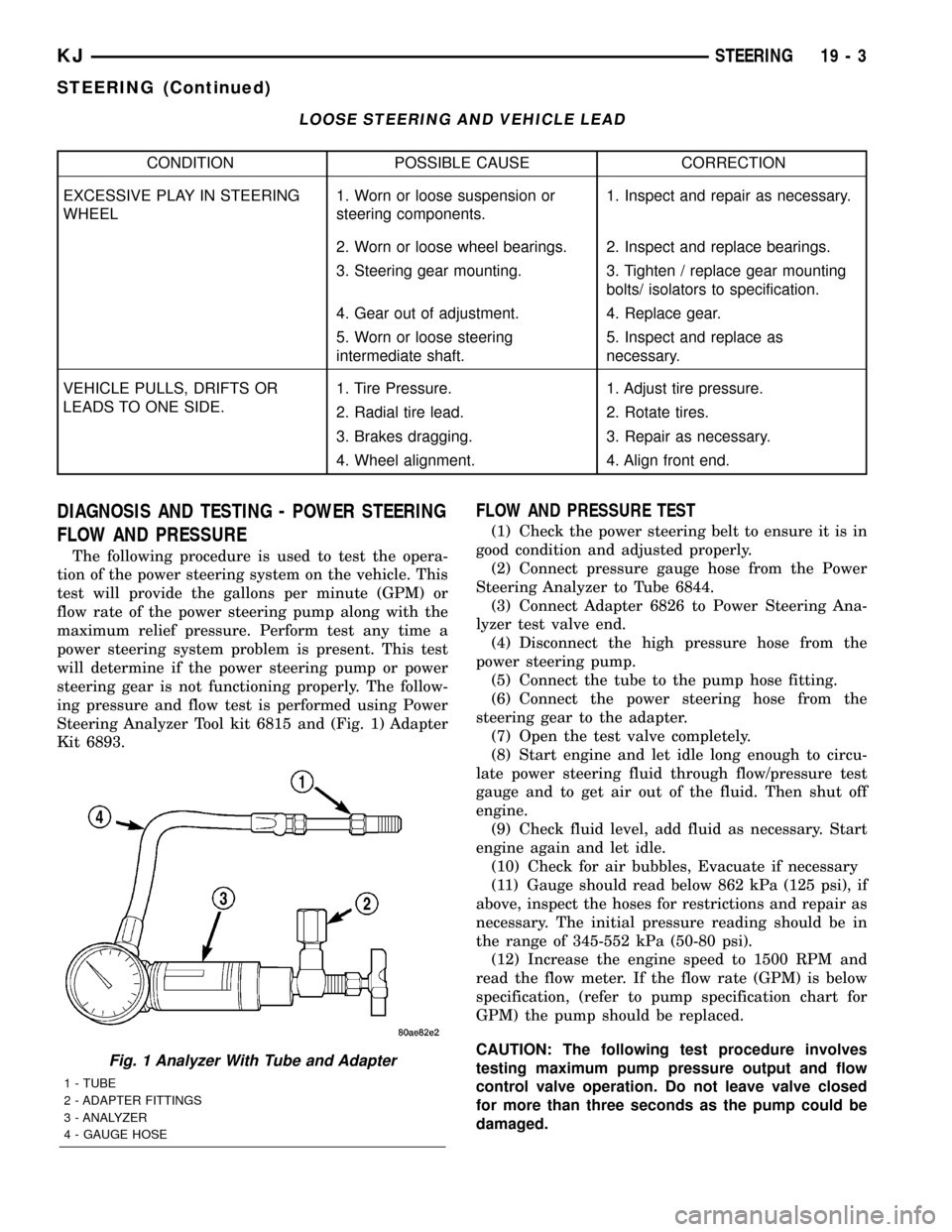
FLOW AND PRESSURE
The following procedure is used to test the opera-
tion of the power steering system on the vehicle. This
test will provide the gallons per minute (GPM) or
flow rate of the power steering pump along with the
maximum relief pressure. Perform test any time a
power steering system problem is present. This test
will determine if the power steering pump or power
steering gear is not functioning properly. The follow-
ing pressure and flow test is performed using Power
Steering Analyzer Tool kit 6815 and (Fig. 1) Adapter
Kit 6893.
FLOW AND PRESSURE TEST
(1) Check the power steering belt to ensure it is in
good condition and adjusted properly.
(2) Connect pressure gauge hose from the Power
Steering Analyzer to Tube 6844.
(3) Connect Adapter 6826 to Power Steering Ana-
lyzer test valve end.
(4) Disconnect the high pressure hose from the
power steering pump.
(5) Connect the tube to the pump hose fitting.
(6) Connect the power steering hose from the
steering gear to the adapter.
(7) Open the test valve completely.
(8) Start engine and let idle long enough to circu-
late power steering fluid through flow/pressure test
gauge and to get air out of the fluid. Then shut off
engine.
(9) Check fluid level, add fluid as necessary. Start
engine again and let idle.
(10) Check for air bubbles, Evacuate if necessary
(11) Gauge should read below 862 kPa (125 psi), if
above, inspect the hoses for restrictions and repair as
necessary. The initial pressure reading should be in
the range of 345-552 kPa (50-80 psi).
(12) Increase the engine speed to 1500 RPM and
read the flow meter. If the flow rate (GPM) is below
specification, (refer to pump specification chart for
GPM) the pump should be replaced.
CAUTION: The following test procedure involves
testing maximum pump pressure output and flow
control valve operation. Do not leave valve closed
for more than three seconds as the pump could be
damaged.
Fig. 1 Analyzer With Tube and Adapter
1 - TUBE
2 - ADAPTER FITTINGS
3 - ANALYZER
4 - GAUGE HOSE
KJSTEERING 19 - 3
STEERING (Continued)
Page 1443 of 1803
GEAR
TABLE OF CONTENTS
page page
GEAR
DESCRIPTION.........................13
OPERATION...........................13
REMOVAL
REMOVAL - 4WD......................13
REMOVAL - 2WD......................14
INSTALLATION
INSTALLATION - 4WD..................14INSTALLATION - 2WD..................14
SPECIFICATIONS
TORQUE CHART......................15
SPECIAL TOOLS
OUTER TIE ROD END REMOVAL TOOL....15
GEAR
DESCRIPTION
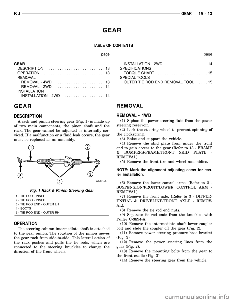
A rack and pinion steering gear (Fig. 1) is made up
of two main components, the pinon shaft and the
rack. The gear cannot be adjusted or internally ser-
viced. If a malfunction or a fluid leak occurs, the gear
must be replaced as an assembly.
OPERATION
The steering column intermediate shaft is attached
to the gear pinion. The rotation of the pinion moves
the gear rack from side-to-side. This lateral action of
the rack pushes and pulls the tie rods, which are
connected to the steering knuckles to change the
direction of the front wheels.
REMOVAL
REMOVAL - 4WD
(1) Siphon the power steering fluid from the power
steering reservoir.
(2) Lock the steering wheel to prevent spinning of
the clockspring.
(3) Raise and support the vehicle.
(4) Remove the skid plate from under the front
end to gain access to the gear (Refer to 13 - FRAME
& BUMPERS/FRAME/FRONT SKID PLATE -
REMOVAL).
(5) Remove the front tire and wheel assemblies.
NOTE: Mark the alignment adjusting cams for eas-
ier installation.
(6) Remove the lower control arms. (Refer to 2 -
SUSPENSION/FRONT/LOWER CONTROL ARM -
REMOVAL).
(7) Remove the front axle. (Refer to 3 - DIFFER-
ENTIAL & DRIVELINE/FRONT AXLE - REMOV-
AL).
(8) Remove the tie rod end nuts.
(9) Separate tie rod ends from the knuckles with
Puller C-3894-A.
(10) Remove the intermediate shaft lower coupler
bolt and slide the coupler off the gear (Fig. 2).
(11) Remove power steering pressure hose bracket
(Fig. 3).
(12) Remove the power steering lines from the
gear (Fig. 2).
(13) Remove the mounting bolts from the gear to
the front cradle (Fig. 3).
(14) Remove the steering gear from the vehicle.
Fig. 1 Rack & Pinion Steering Gear
1 - TIE ROD - INNER
2 - TIE ROD - INNER
3 - TIE ROD END - OUTER LH
4 - BOOTS
5 - TIE ROD END - OUTER RH
KJGEAR 19 - 13