2002 JEEP LIBERTY Transmission is removal
[x] Cancel search: Transmission is removalPage 1271 of 1803
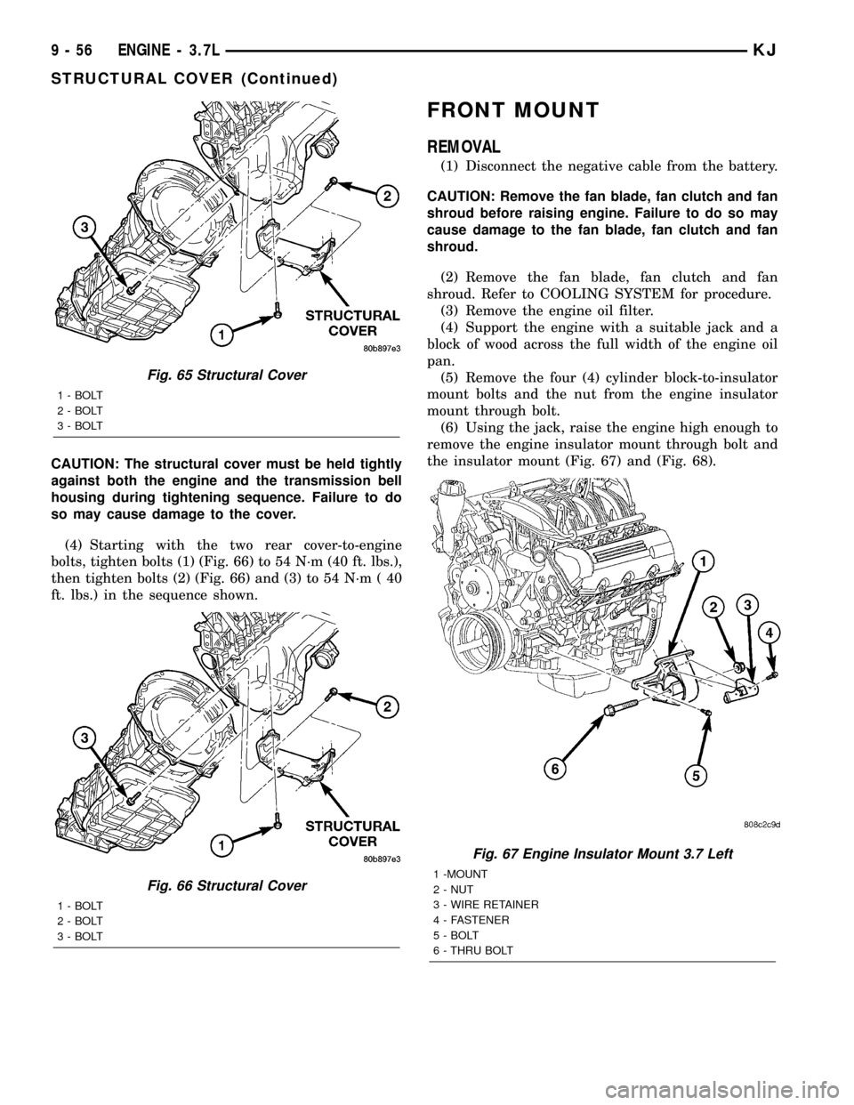
CAUTION: The structural cover must be held tightly
against both the engine and the transmission bell
housing during tightening sequence. Failure to do
so may cause damage to the cover.
(4) Starting with the two rear cover-to-engine
bolts, tighten bolts (1) (Fig. 66) to 54 N´m (40 ft. lbs.),
then tighten bolts (2) (Fig. 66) and (3) to 54 N´m ( 40
ft. lbs.) in the sequence shown.
FRONT MOUNT
REMOVAL
(1) Disconnect the negative cable from the battery.
CAUTION: Remove the fan blade, fan clutch and fan
shroud before raising engine. Failure to do so may
cause damage to the fan blade, fan clutch and fan
shroud.
(2) Remove the fan blade, fan clutch and fan
shroud. Refer to COOLING SYSTEM for procedure.
(3) Remove the engine oil filter.
(4) Support the engine with a suitable jack and a
block of wood across the full width of the engine oil
pan.
(5) Remove the four (4) cylinder block-to-insulator
mount bolts and the nut from the engine insulator
mount through bolt.
(6) Using the jack, raise the engine high enough to
remove the engine insulator mount through bolt and
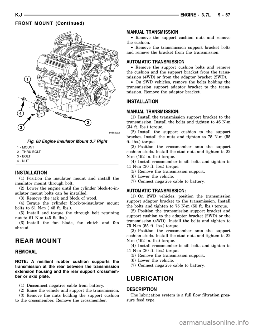
the insulator mount (Fig. 67) and (Fig. 68).
Fig. 65 Structural Cover
1 - BOLT
2 - BOLT
3 - BOLT
Fig. 66 Structural Cover
1 - BOLT
2 - BOLT
3 - BOLT
Fig. 67 Engine Insulator Mount 3.7 Left
1 -MOUNT
2 - NUT
3 - WIRE RETAINER
4 - FASTENER
5 - BOLT
6 - THRU BOLT
9 - 56 ENGINE - 3.7LKJ
STRUCTURAL COVER (Continued)
Page 1272 of 1803
INSTALLATION
(1) Position the insulator mount and install the
insulator mount through bolt.
(2) Lower the engine until the cylinder block-to-in-
sulator mount bolts can be installed.
(3) Remove the jack and block of wood.
(4) Torque the cylinder block-to-insulator mount
bolts to 61 N´m ( 45 ft. lbs.).
(5) Install and torque the through bolt retaining
nut to 61 N´m (45 ft. lbs.).
(6) Install the fan blade, fan clutch and fan
shroud.
REAR MOUNT
REMOVAL
NOTE: A resilient rubber cushion supports the
transmission at the rear between the transmission
extension housing and the rear support crossmem-
ber or skid plate.
(1) Disconnect negative cable from battery.
(2) Raise the vehicle and support the transmission.
(3) Remove the nuts holding the support cushion
to the crossmember. Remove the crossmember.
MANUAL TRANSMISSION
²Remove the support cushion nuts and remove
the cushion.
²Remove the transmission support bracket bolts
and remove the bracket from the transmission.
AUTOMATIC TRANSMISSION
²Remove the support cushion bolts and remove
the cushion and the support bracket from the trans-
mission (4WD) or from the adaptor bracket (2WD).
²On 2WD vehicles, remove the bolts holding the
transmission support adaptor bracket to the trans-
mission. Remove the adaptor bracket.
INSTALLATION
MANUAL TRANSMISSION:
(1) Install the transmission support bracket to the
transmission. Install the bolts and tighten to 46 N´m
(34 ft. lbs.) torque.
(2) Install the support cushion to the support
bracket. Install the nuts and tighten to 75 N´m (55
ft. lbs.) torque.
(3) Position the crossmember onto the support
cushion studs. Install the stud nuts and tighten to 22
N´m (192 in. lbs) torque.
(4) Install crossmember-to-sill bolts and tighten to
41 N´m (30 ft. lbs.) torque.
(5) Remove the transmission support.
(6) Lower the vehicle.
(7) Connect negative cable to battery.
AUTOMATIC TRANSMISSION:
(1) On 2WD vehicles, position the transmission
support adaptor bracket to the transmission. Install
the bolts and tighten to 75 N´m (55 ft. lbs.) torque.
(2) Position the transmission support bracket and
support cushion to the adaptor bracket (2WD) or the
transmission (4WD). Install the bolts and tighten to
75 N´m (55 ft. lbs.) torque.
(3) Position the crossmember onto the support
cushion studs. Install the stud nuts and tighten to 22
N´m (192 in. lbs) torque.
(4) Install crossmember-to-sill bolts and tighten to
41 N´m (30 ft. lbs.) torque.
(5) Remove the transmission support.
(6) Lower the vehicle.
(7) Connect negative cable to battery.
LUBRICATION
DESCRIPTION
The lubrication system is a full flow filtration pres-
sure feed type.
Fig. 68 Engine Insulator Mount 3.7 Right
1 - MOUNT
2 - THRU BOLT
3 - BOLT
4 - NUT
KJENGINE - 3.7L 9 - 57
FRONT MOUNT (Continued)
Page 1309 of 1803
NOTE: Plastigage is available in a variety of clear-
ance ranges. Use the most appropriate range for
the specifications you are checking.
(4) Install the proper crankshaft bearings to
achieve the specified bearing clearances. (Refer to 9 -
ENGINE/ENGINE BLOCK/CRANKSHAFT MAIN
BEARINGS - STANDARD PROCEDURE) (Refer to 9
- ENGINE/ENGINE BLOCK/CONNECTING ROD
BEARINGS - STANDARD PROCEDURE)
REMOVAL - ENGINE ASSEMBLY
(1) Disconnect the battery negative cable.
(2) Remove hood. Mark hood hinge location for
reinstallation.
(3) Remove air cleaner assembly.
(4) Remove radiator core support bracket.
(5) Remove fan shroud with electric fan assembly.
(6) Remove drive belt.
NOTE: It is NOT necessary to discharge the A/C
system to remove the engine.
(7) Remove A/C compressor and secure away from
engine with lines attached.
(8) Remove generator and secure away from
engine.
NOTE: Do NOT remove the phenolic pulley from the
P/S pump. It is not required for P/S pump removal.
(9) Remove power steering pump with lines
attached and secure away from engine.
(10) Drain cooling system.
(11) Remove coolant bottle.
(12) Disconnect the heater hoses from the engine.
(13) Disconnect heater hoses from heater core and
remove hose assembly.
(14) Disconnect throttle and speed control cables.
(15) Remove upper radiator hose from engine.
(16) Remove lower radiator hose from engine.
(17) Disconnect the engine to body ground straps
at the left side of cowl.
(18) Disconnect the engine wiring harness at the
following points:
²Intake air temperature (IAT) sensor
²Fuel Injectors
²Throttle Position (TPS) Switch
²Idle Air Control (IAC) Motor
²Engine Oil Pressure Switch
²Engine Coolant Temperature (ECT) Sensor
²Manifold Absolute Pressure MAP) Sensor
²Camshaft Position (CMP) Sensor
²Coil Over Plugs
²Crankshaft Position Sensor
(19) Remove coil over plugs.
(20) Release fuel rail pressure.(21) Remove fuel rail and secure away from
engine.
(22) Remove the PCV hose.
(23) Remove the breather hoses.
(24) Remove the vacuum hose for the power brake
booster.
(25) Disconnect knock sensors.
(26) Secure the left and right engine wiring har-
nesses away from engine.
(27) Raise vehicle.
(28) Disconnect oxygen sensor wiring.
(29) Disconnect crankshaft postion sensor.
(30) Disconnect the engine block heater power
cable, if equipped.
(31) Disconnect the front propshaft at the front
differential and secure out of way.
(32) Remove the starter.
(33) Remove the ground straps from the engine
(34) Disconnect the exhaust pipes at the manifold.
(35) Remove the structural cover, if equipped.
(36) Remove torque convertor bolts, and mark
location for reassembly.
(37) Remove transmission bellhousing to engine
bolts.
(38) Loosen left and right engine mount thru bolts.
NOTE: It is not necessary to completely remove
engine mount thru bolts, for engine removal.
(39) Lower the vehicle.
(40) Support the transmission with a suitable jack.
(41) Connect a suitable engine hoist to the engine.
CAUTION: The 2.4L engine with manual transmis-
sions, can be removed without removing the man-
ual transmission. Use caution when attempting this
procedure as the clearance is tight.
(42) Remove engine from vehicle.
INSTALLATION - ENGINE ASSEMBLY
(1) Position the engine in the vehicle.
CAUTION: Use caution when installing 2.4L engine
into vehicle equipped with manual transmission, as
clearance is tight.
(2) Install both left and right side engine mounts
into the frame mounts.
(3) Raise the vehicle.
(4) Install the transmission bellhousing to engine
mounting bolts. Tighten the bolts to 41 N´m (30ft.
lbs.).
(5) Tighten the engine mount thru bolts.
(6) Install the torque convertor bolts.
(7) Connect the ground straps on the left and right
side of the engine.
9s - 12 ENGINEKJ
ENGINE - 2.4L (Continued)
Page 1335 of 1803
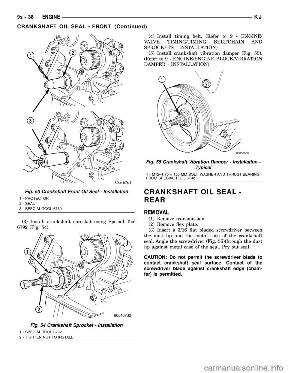
(3) Install crankshaft sprocket using Special Tool
6792 (Fig. 54).(4) Install timing belt. (Refer to 9 - ENGINE/
VALVE TIMING/TIMING BELT/CHAIN AND
SPROCKETS - INSTALLATION)
(5) Install crankshaft vibration damper (Fig. 55).
(Refer to 9 - ENGINE/ENGINE BLOCK/VIBRATION
DAMPER - INSTALLATION)
CRANKSHAFT OIL SEAL -
REAR
REMOVAL
(1) Remove transmission.
(2) Remove flex plate.
(3) Insert a 3/16 flat bladed screwdriver between
the dust lip and the metal case of the crankshaft
seal. Angle the screwdriver (Fig. 56)through the dust
lip against metal case of the seal. Pry out seal.
CAUTION: Do not permit the screwdriver blade to
contact crankshaft seal surface. Contact of the
screwdriver blade against crankshaft edge (cham-
fer) is permitted.
Fig. 53 Crankshaft Front Oil Seal - Installation
1 - PROTECTOR
2 - SEAL
3 - SPECIAL TOOL 6780
Fig. 54 Crankshaft Sprocket - Installation
1 - SPECIAL TOOL 6792
2 - TIGHTEN NUT TO INSTALL
Fig. 55 Crankshaft Vibration Damper - Installation -
Typical
1 - M12±1.75 ý 150 MM BOLT, WASHER AND THRUST BEARING
FROM SPECIAL TOOL 6792
9s - 38 ENGINEKJ
CRANKSHAFT OIL SEAL - FRONT (Continued)
Page 1337 of 1803
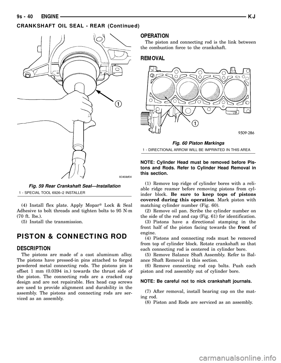
(4) Install flex plate. Apply MopartLock & Seal
Adhesive to bolt threads and tighten bolts to 95 N´m
(70 ft. lbs.).
(5) Install the transmission.
PISTON & CONNECTING ROD
DESCRIPTION
The pistons are made of a cast aluminum alloy.
The pistons have pressed-in pins attached to forged
powdered metal connecting rods. The pistons pin is
offset 1 mm (0.0394 in.) towards the thrust side of
the piston. The connecting rods are a cracked cap
design and are not repairable. Hex head cap screws
are used to provide alignment and durability in the
assembly. The pistons and connecting rods are ser-
viced as an assembly.
OPERATION
The piston and connecting rod is the link between
the combustion force to the crankshaft.
REMOVAL
NOTE: Cylinder Head must be removed before Pis-
tons and Rods. Refer to Cylinder Head Removal in
this section.
(1) Remove top ridge of cylinder bores with a reli-
able ridge reamer before removing pistons from cyl-
inder block.Be sure to keep tops of pistons
covered during this operation. Mark piston with
matching cylinder number (Fig. 60).
(2) Remove oil pan. Scribe the cylinder number on
the side of the rod and cap (Fig. 61) for identification.
(3) Pistons have a directional stamping in the
front half of the piston facing towards thefrontof
engine.
(4) Pistons and connecting rods must be removed
from top of cylinder block. Rotate crankshaft so that
each connecting rod is centered in cylinder bore.
(5) Remove Balance Shaft Assembly. Refer to Bal-
ance Shaft Removal in this section.
(6) Remove connecting rod cap bolts. Push each
piston and rod assembly out of cylinder bore.
NOTE: Be careful not to nick crankshaft journals.
(7) After removal, install bearing cap on the mat-
ing rod.
(8) Piston and Rods are serviced as an assembly.
Fig. 59 Rear Crankshaft SealÐInstallation
1 - SPECIAL TOOL 6926±2 INSTALLER
Fig. 60 Piston Markings
1 - DIRECTIONAL ARROW WILL BE IMPRINTED IN THIS AREA
9s - 40 ENGINEKJ
CRANKSHAFT OIL SEAL - REAR (Continued)
Page 1341 of 1803
STRUCTURAL COLLAR
REMOVAL
(1) Raise vehicle on hoist.
(2) Remove structural collar attaching bolts.
(3) Remove collar.
INSTALLATION
CAUTION: Torque procedure for the structural collar
must be followed or damage could occur to oil pan
and collar.
(1) Perform the following steps for installing struc-
tural collar.
²Step 1: Position collar between transmission and
oil pan. Install collar to transmission bolts,hand
start only.
²Step 2: Install collar to oil pan bolts,hand snug
only.
²Step 3: Tighten collar to transmission bolts.
²Step 4: Tighten collar to oil pan bolts.
(2) Lower vehicle.
ENGINE MOUNTING
DESCRIPTION
The engine mounting system consist of three
mounts; right and a left side support the powertrain,
and rear mount to control powertrain torque. The
mounts are of molded rubber material.
FRONT MOUNT
REMOVAL
(1) Raise vehicle on hoist.
(2) Remove the front engine mount through bolt
from the insulator.
(3) Remove the engine front mount bolts and
remove the insulator assembly.
(4) Remove the front mounting bracket from
engine, if necessary.
INSTALLATION
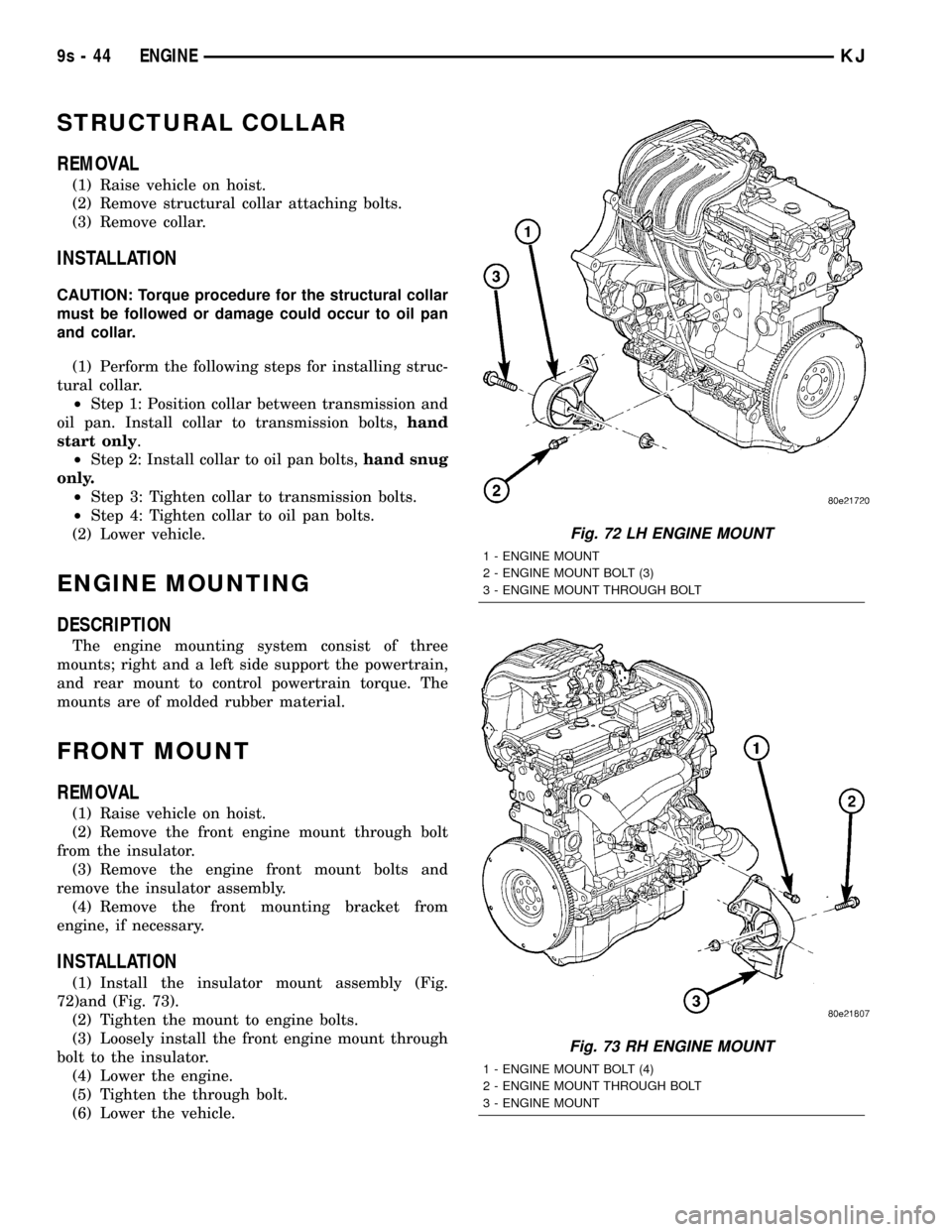
(1) Install the insulator mount assembly (Fig.
72)and (Fig. 73).
(2) Tighten the mount to engine bolts.
(3) Loosely install the front engine mount through
bolt to the insulator.
(4) Lower the engine.
(5) Tighten the through bolt.
(6) Lower the vehicle.
Fig. 72 LH ENGINE MOUNT
1 - ENGINE MOUNT
2 - ENGINE MOUNT BOLT (3)
3 - ENGINE MOUNT THROUGH BOLT
Fig. 73 RH ENGINE MOUNT
1 - ENGINE MOUNT BOLT (4)
2 - ENGINE MOUNT THROUGH BOLT
3 - ENGINE MOUNT
9s - 44 ENGINEKJ
Page 1342 of 1803
REAR MOUNT
REMOVAL
NOTE: A resilient rubber cushion supports the
transmission at the rear between the transmission
extension housing and the rear support crossmem-
ber or skid plate.
(1) Disconnect negative cable from battery.
(2) Raise the vehicle and support the transmission.
(3) Remove the nuts holding the support cushion
to the crossmember. Remove the crossmember.
MANUAL TRANSMISSION
a. Remove the support cushion nuts and remove
the cushion.
b. Remove the transmission support bracket bolts
and remove the bracket from the transmission.
AUTOMATIC TRANSMISSION
c. Remove the support cushion bolts and remove
the cushion and the support bracket from the trans-
mission (4WD) or from the adaptor bracket (2WD).
d. On 2WD vehicles, remove the bolts holding the
transmission support adaptor bracket to the trans-
mission. Remove the adaptor bracket.
INSTALLATION
MANUAL TRANSMISSION:
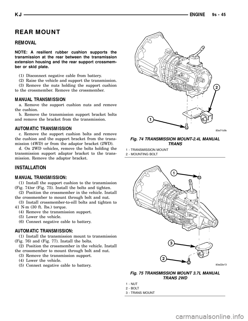
(1) Install the support cushion to the transmission
(Fig. 74)or (Fig. 75). Install the bolts and tighten.
(2) Position the crossmember in the vehicle. Install
the crossmember to mount through bolt and nut.
(3) Install crossmember-to-sill bolts and tighten to
41 N´m (30 ft. lbs.) torque.
(4) Remove the transmission support.
(5) Lower the vehicle.
(6) Connect negative cable to battery.
AUTOMATIC TRANSMISSION:
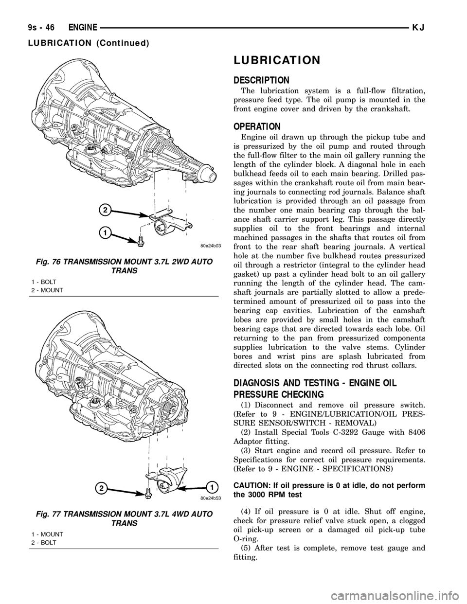
(1) Install the transmission mount to transmission
(Fig. 76) and (Fig. 77). Install the bolts.
(2) Position the crossmember in the vehicle. Install
the crossmember to mount through bolt and nut.
(3) Remove the transmission support.
(4) Lower the vehicle.
(5) Connect negative cable to battery.
Fig. 74 TRANSMISSION MOUNT-2.4L MANUAL
TRANS
1 - TRANSMISSION MOUNT
2 - MOUNTING BOLT
Fig. 75 TRANSMISSION MOUNT 3.7L MANUAL
TRANS 2WD
1 - NUT
2 - BOLT
3 - TRANS MOUNT
KJENGINE9s-45
Page 1343 of 1803
LUBRICATION
DESCRIPTION
The lubrication system is a full-flow filtration,
pressure feed type. The oil pump is mounted in the
front engine cover and driven by the crankshaft.
OPERATION
Engine oil drawn up through the pickup tube and
is pressurized by the oil pump and routed through
the full-flow filter to the main oil gallery running the
length of the cylinder block. A diagonal hole in each
bulkhead feeds oil to each main bearing. Drilled pas-
sages within the crankshaft route oil from main bear-
ing journals to connecting rod journals. Balance shaft
lubrication is provided through an oil passage from
the number one main bearing cap through the bal-
ance shaft carrier support leg. This passage directly
supplies oil to the front bearings and internal
machined passages in the shafts that routes oil from
front to the rear shaft bearing journals. A vertical
hole at the number five bulkhead routes pressurized
oil through a restrictor (integral to the cylinder head
gasket) up past a cylinder head bolt to an oil gallery
running the length of the cylinder head. The cam-
shaft journals are partially slotted to allow a prede-
termined amount of pressurized oil to pass into the
bearing cap cavities. Lubrication of the camshaft
lobes are provided by small holes in the camshaft
bearing caps that are directed towards each lobe. Oil
returning to the pan from pressurized components
supplies lubrication to the valve stems. Cylinder
bores and wrist pins are splash lubricated from
directed slots on the connecting rod thrust collars.
DIAGNOSIS AND TESTING - ENGINE OIL
PRESSURE CHECKING
(1) Disconnect and remove oil pressure switch.
(Refer to 9 - ENGINE/LUBRICATION/OIL PRES-
SURE SENSOR/SWITCH - REMOVAL)
(2) Install Special Tools C-3292 Gauge with 8406
Adaptor fitting.
(3) Start engine and record oil pressure. Refer to
Specifications for correct oil pressure requirements.
(Refer to 9 - ENGINE - SPECIFICATIONS)
CAUTION: If oil pressure is 0 at idle, do not perform
the 3000 RPM test
(4) If oil pressure is 0 at idle. Shut off engine,
check for pressure relief valve stuck open, a clogged
oil pick-up screen or a damaged oil pick-up tube
O-ring.
(5) After test is complete, remove test gauge and
fitting.
Fig. 76 TRANSMISSION MOUNT 3.7L 2WD AUTO
TRANS
1 - BOLT
2 - MOUNT
Fig. 77 TRANSMISSION MOUNT 3.7L 4WD AUTO
TRANS
1 - MOUNT
2 - BOLT
9s - 46 ENGINEKJ
LUBRICATION (Continued)