2002 JEEP LIBERTY Window connector
[x] Cancel search: Window connectorPage 1147 of 1803
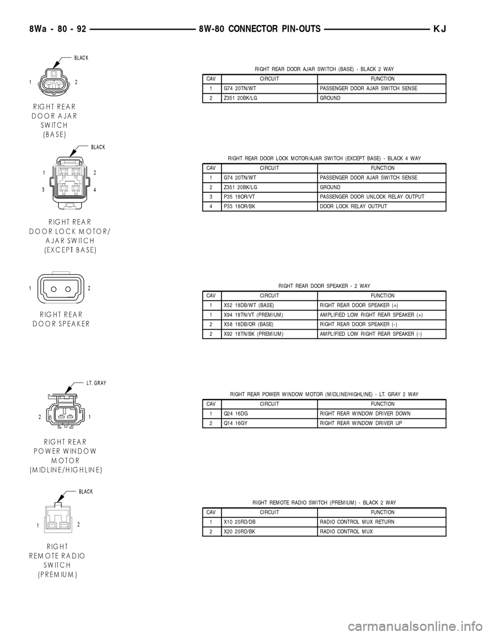
RIGHT REAR DOOR AJAR SWITCH (BASE) - BLACK 2 WAY
CAV CIRCUIT FUNCTION
1 G74 20TN/WT PASSENGER DOOR AJAR SWITCH SENSE
2 Z351 20BK/LG GROUND
RIGHT REAR DOOR LOCK MOTOR/AJAR SWITCH (EXCEPT BASE) - BLACK 4 WAY
CAV CIRCUIT FUNCTION
1 G74 20TN/WT PASSENGER DOOR AJAR SWITCH SENSE
2 Z351 20BK/LG GROUND
3 P35 18OR/VT PASSENGER DOOR UNLOCK RELAY OUTPUT
4 P33 18OR/BK DOOR LOCK RELAY OUTPUT
RIGHT REAR DOOR SPEAKER-2WAY
CAV CIRCUIT FUNCTION
1 X52 18DB/WT (BASE) RIGHT REAR DOOR SPEAKER (+)
1 X94 18TN/VT (PREMIUM) AMPLIFIED LOW RIGHT REAR SPEAKER (+)
2 X58 18DB/OR (BASE) RIGHT REAR DOOR SPEAKER (-)
2 X92 18TN/BK (PREMIUM) AMPLIFIED LOW RIGHT REAR SPEAKER (-)
RIGHT REAR POWER WINDOW MOTOR (MIDLINE/HIGHLINE) - LT. GRAY 2 WAY
CAV CIRCUIT FUNCTION
1 Q24 16DG RIGHT REAR WINDOW DRIVER DOWN
2 Q14 16GY RIGHT REAR WINDOW DRIVER UP
RIGHT REMOTE RADIO SWITCH (PREMIUM) - BLACK 2 WAY
CAV CIRCUIT FUNCTION
1 X10 20RD/DB RADIO CONTROL MUX RETURN
2 X20 20RD/BK RADIO CONTROL MUX
8Wa - 80 - 92 8W-80 CONNECTOR PIN-OUTSKJ
Page 1156 of 1803
8W-91 CONNECTOR/GROUND/SPLICE LOCATION
TABLE OF CONTENTS
page
CONNECTOR/GROUND/SPLICE LOCATION
DESCRIPTION..........................1
CONNECTOR/GROUND/SPLICE
LOCATION
DESCRIPTION
This section provides illustrations identifying con-
nector, ground, and splice locations in the vehicle.Connector, ground, and splice indexes are provided.
Use the wiring diagrams in each section for connec-
tor, ground, and splice identification. Refer to the
appropriate index for the proper figure number. For
items that are not shown in this section N/S is placed
in the Fig. column.
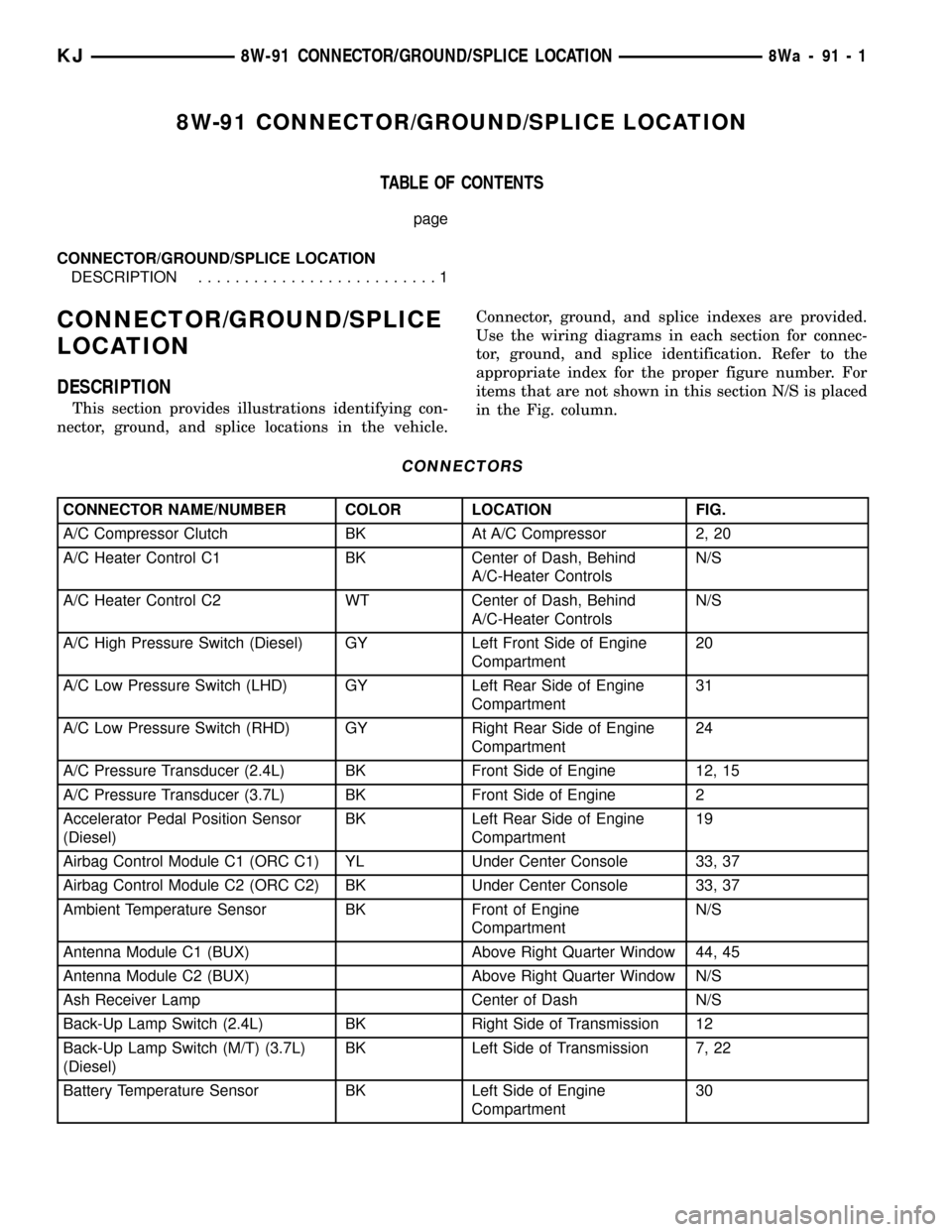
CONNECTORS
CONNECTOR NAME/NUMBER COLOR LOCATION FIG.
A/C Compressor Clutch BK At A/C Compressor 2, 20
A/C Heater Control C1 BK Center of Dash, Behind
A/C-Heater ControlsN/S
A/C Heater Control C2 WT Center of Dash, Behind
A/C-Heater ControlsN/S
A/C High Pressure Switch (Diesel) GY Left Front Side of Engine
Compartment20
A/C Low Pressure Switch (LHD) GY Left Rear Side of Engine
Compartment31
A/C Low Pressure Switch (RHD) GY Right Rear Side of Engine
Compartment24
A/C Pressure Transducer (2.4L) BK Front Side of Engine 12, 15
A/C Pressure Transducer (3.7L) BK Front Side of Engine 2
Accelerator Pedal Position Sensor
(Diesel)BK Left Rear Side of Engine
Compartment19
Airbag Control Module C1 (ORC C1) YL Under Center Console 33, 37
Airbag Control Module C2 (ORC C2) BK Under Center Console 33, 37
Ambient Temperature Sensor BK Front of Engine
CompartmentN/S
Antenna Module C1 (BUX) Above Right Quarter Window 44, 45
Antenna Module C2 (BUX) Above Right Quarter Window N/S
Ash Receiver Lamp Center of Dash N/S
Back-Up Lamp Switch (2.4L) BK Right Side of Transmission 12
Back-Up Lamp Switch (M/T) (3.7L)
(Diesel)BK Left Side of Transmission 7, 22
Battery Temperature Sensor BK Left Side of Engine
Compartment30
KJ8W-91 CONNECTOR/GROUND/SPLICE LOCATION8Wa-91-1
Page 1161 of 1803
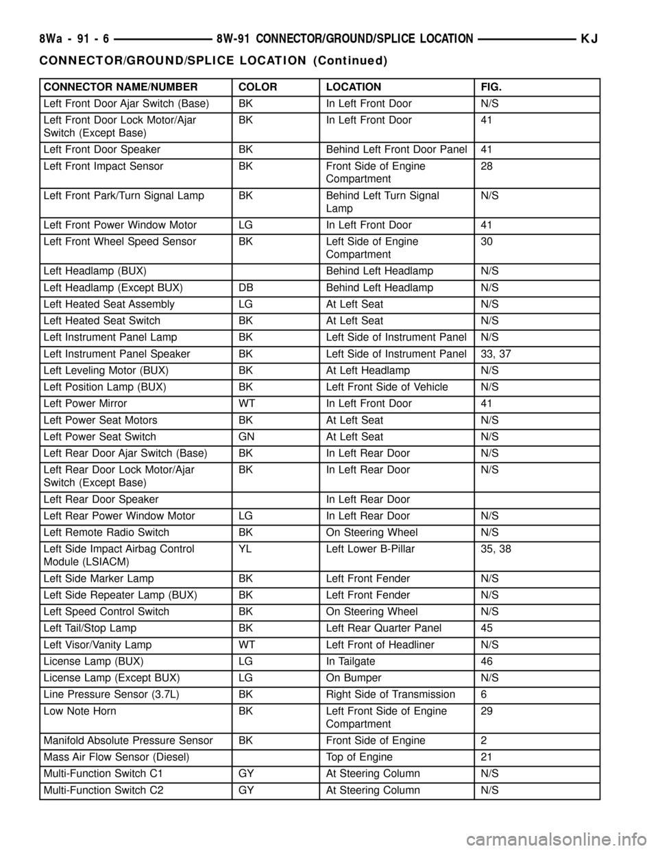
CONNECTOR NAME/NUMBER COLOR LOCATION FIG.
Left Front Door Ajar Switch (Base) BK In Left Front Door N/S
Left Front Door Lock Motor/Ajar
Switch (Except Base)BK In Left Front Door 41
Left Front Door Speaker BK Behind Left Front Door Panel 41
Left Front Impact Sensor BK Front Side of Engine
Compartment28
Left Front Park/Turn Signal Lamp BK Behind Left Turn Signal
LampN/S
Left Front Power Window Motor LG In Left Front Door 41
Left Front Wheel Speed Sensor BK Left Side of Engine
Compartment30
Left Headlamp (BUX) Behind Left Headlamp N/S
Left Headlamp (Except BUX) DB Behind Left Headlamp N/S
Left Heated Seat Assembly LG At Left Seat N/S
Left Heated Seat Switch BK At Left Seat N/S
Left Instrument Panel Lamp BK Left Side of Instrument Panel N/S
Left Instrument Panel Speaker BK Left Side of Instrument Panel 33, 37
Left Leveling Motor (BUX) BK At Left Headlamp N/S
Left Position Lamp (BUX) BK Left Front Side of Vehicle N/S
Left Power Mirror WT In Left Front Door 41
Left Power Seat Motors BK At Left Seat N/S
Left Power Seat Switch GN At Left Seat N/S
Left Rear Door Ajar Switch (Base) BK In Left Rear Door N/S
Left Rear Door Lock Motor/Ajar
Switch (Except Base)BK In Left Rear Door N/S
Left Rear Door Speaker In Left Rear Door
Left Rear Power Window Motor LG In Left Rear Door N/S
Left Remote Radio Switch BK On Steering Wheel N/S
Left Side Impact Airbag Control
Module (LSIACM)YL Left Lower B-Pillar 35, 38
Left Side Marker Lamp BK Left Front Fender N/S
Left Side Repeater Lamp (BUX) BK Left Front Fender N/S
Left Speed Control Switch BK On Steering Wheel N/S
Left Tail/Stop Lamp BK Left Rear Quarter Panel 45
Left Visor/Vanity Lamp WT Left Front of Headliner N/S
License Lamp (BUX) LG In Tailgate 46
License Lamp (Except BUX) LG On Bumper N/S
Line Pressure Sensor (3.7L) BK Right Side of Transmission 6
Low Note Horn BK Left Front Side of Engine
Compartment29
Manifold Absolute Pressure Sensor BK Front Side of Engine 2
Mass Air Flow Sensor (Diesel) Top of Engine 21
Multi-Function Switch C1 GY At Steering Column N/S
Multi-Function Switch C2 GY At Steering Column N/S
8Wa - 91 - 6 8W-91 CONNECTOR/GROUND/SPLICE LOCATIONKJ
CONNECTOR/GROUND/SPLICE LOCATION (Continued)
Page 1162 of 1803
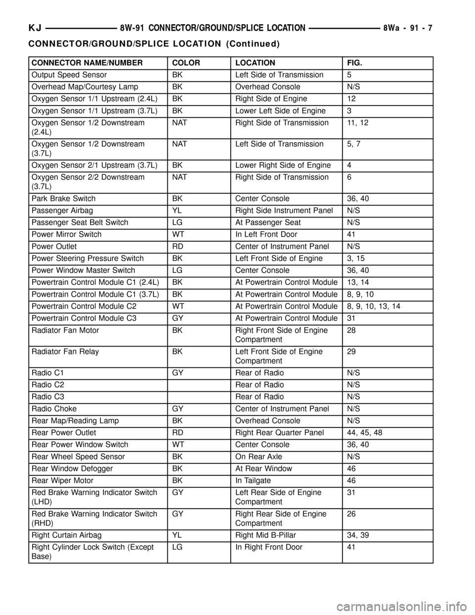
CONNECTOR NAME/NUMBER COLOR LOCATION FIG.
Output Speed Sensor BK Left Side of Transmission 5
Overhead Map/Courtesy Lamp BK Overhead Console N/S
Oxygen Sensor 1/1 Upstream (2.4L) BK Right Side of Engine 12
Oxygen Sensor 1/1 Upstream (3.7L) BK Lower Left Side of Engine 3
Oxygen Sensor 1/2 Downstream
(2.4L)NAT Right Side of Transmission 11, 12
Oxygen Sensor 1/2 Downstream
(3.7L)NAT Left Side of Transmission 5, 7
Oxygen Sensor 2/1 Upstream (3.7L) BK Lower Right Side of Engine 4
Oxygen Sensor 2/2 Downstream
(3.7L)NAT Right Side of Transmission 6
Park Brake Switch BK Center Console 36, 40
Passenger Airbag YL Right Side Instrument Panel N/S
Passenger Seat Belt Switch LG At Passenger Seat N/S
Power Mirror Switch WT In Left Front Door 41
Power Outlet RD Center of Instrument Panel N/S
Power Steering Pressure Switch BK Left Front Side of Engine 3, 15
Power Window Master Switch LG Center Console 36, 40
Powertrain Control Module C1 (2.4L) BK At Powertrain Control Module 13, 14
Powertrain Control Module C1 (3.7L) BK At Powertrain Control Module 8, 9, 10
Powertrain Control Module C2 WT At Powertrain Control Module 8, 9, 10, 13, 14
Powertrain Control Module C3 GY At Powertrain Control Module 31
Radiator Fan Motor BK Right Front Side of Engine
Compartment28
Radiator Fan Relay BK Left Front Side of Engine
Compartment29
Radio C1 GY Rear of Radio N/S
Radio C2 Rear of Radio N/S
Radio C3 Rear of Radio N/S
Radio Choke GY Center of Instrument Panel N/S
Rear Map/Reading Lamp BK Overhead Console N/S
Rear Power Outlet RD Right Rear Quarter Panel 44, 45, 48
Rear Power Window Switch WT Center Console 36, 40
Rear Wheel Speed Sensor BK On Rear Axle N/S
Rear Window Defogger BK At Rear Window 46
Rear Wiper Motor BK In Tailgate 46
Red Brake Warning Indicator Switch
(LHD)GY Left Rear Side of Engine
Compartment31
Red Brake Warning Indicator Switch
(RHD)GY Right Rear Side of Engine
Compartment26
Right Curtain Airbag YL Right Mid B-Pillar 34, 39
Right Cylinder Lock Switch (Except
Base)LG In Right Front Door 41
KJ8W-91 CONNECTOR/GROUND/SPLICE LOCATION8Wa-91-7
CONNECTOR/GROUND/SPLICE LOCATION (Continued)
Page 1163 of 1803
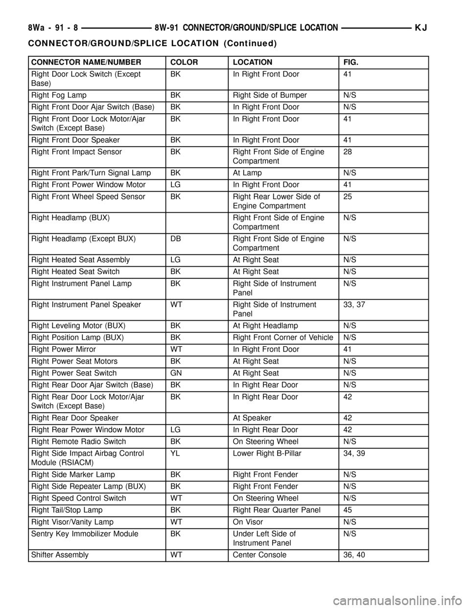
CONNECTOR NAME/NUMBER COLOR LOCATION FIG.
Right Door Lock Switch (Except
Base)BK In Right Front Door 41
Right Fog Lamp BK Right Side of Bumper N/S
Right Front Door Ajar Switch (Base) BK In Right Front Door N/S
Right Front Door Lock Motor/Ajar
Switch (Except Base)BK In Right Front Door 41
Right Front Door Speaker BK In Right Front Door 41
Right Front Impact Sensor BK Right Front Side of Engine
Compartment28
Right Front Park/Turn Signal Lamp BK At Lamp N/S
Right Front Power Window Motor LG In Right Front Door 41
Right Front Wheel Speed Sensor BK Right Rear Lower Side of
Engine Compartment25
Right Headlamp (BUX) Right Front Side of Engine
CompartmentN/S
Right Headlamp (Except BUX) DB Right Front Side of Engine
CompartmentN/S
Right Heated Seat Assembly LG At Right Seat N/S
Right Heated Seat Switch BK At Right Seat N/S
Right Instrument Panel Lamp BK Right Side of Instrument
PanelN/S
Right Instrument Panel Speaker WT Right Side of Instrument
Panel33, 37
Right Leveling Motor (BUX) BK At Right Headlamp N/S
Right Position Lamp (BUX) BK Right Front Corner of Vehicle N/S
Right Power Mirror WT In Right Front Door 41
Right Power Seat Motors BK At Right Seat N/S
Right Power Seat Switch GN At Right Seat N/S
Right Rear Door Ajar Switch (Base) BK In Right Rear Door N/S
Right Rear Door Lock Motor/Ajar
Switch (Except Base)BK In Right Rear Door 42
Right Rear Door Speaker At Speaker 42
Right Rear Power Window Motor LG In Right Rear Door 42
Right Remote Radio Switch BK On Steering Wheel N/S
Right Side Impact Airbag Control
Module (RSIACM)YL Lower Right B-Pillar 34, 39
Right Side Marker Lamp BK Right Front Fender N/S
Right Side Repeater Lamp (BUX) BK Right Front Fender N/S
Right Speed Control Switch WT On Steering Wheel N/S
Right Tail/Stop Lamp BK Right Rear Quarter Panel 45
Right Visor/Vanity Lamp WT On Visor N/S
Sentry Key Immobilizer Module BK Under Left Side of
Instrument PanelN/S
Shifter Assembly WT Center Console 36, 40
8Wa - 91 - 8 8W-91 CONNECTOR/GROUND/SPLICE LOCATIONKJ
CONNECTOR/GROUND/SPLICE LOCATION (Continued)
Page 1168 of 1803
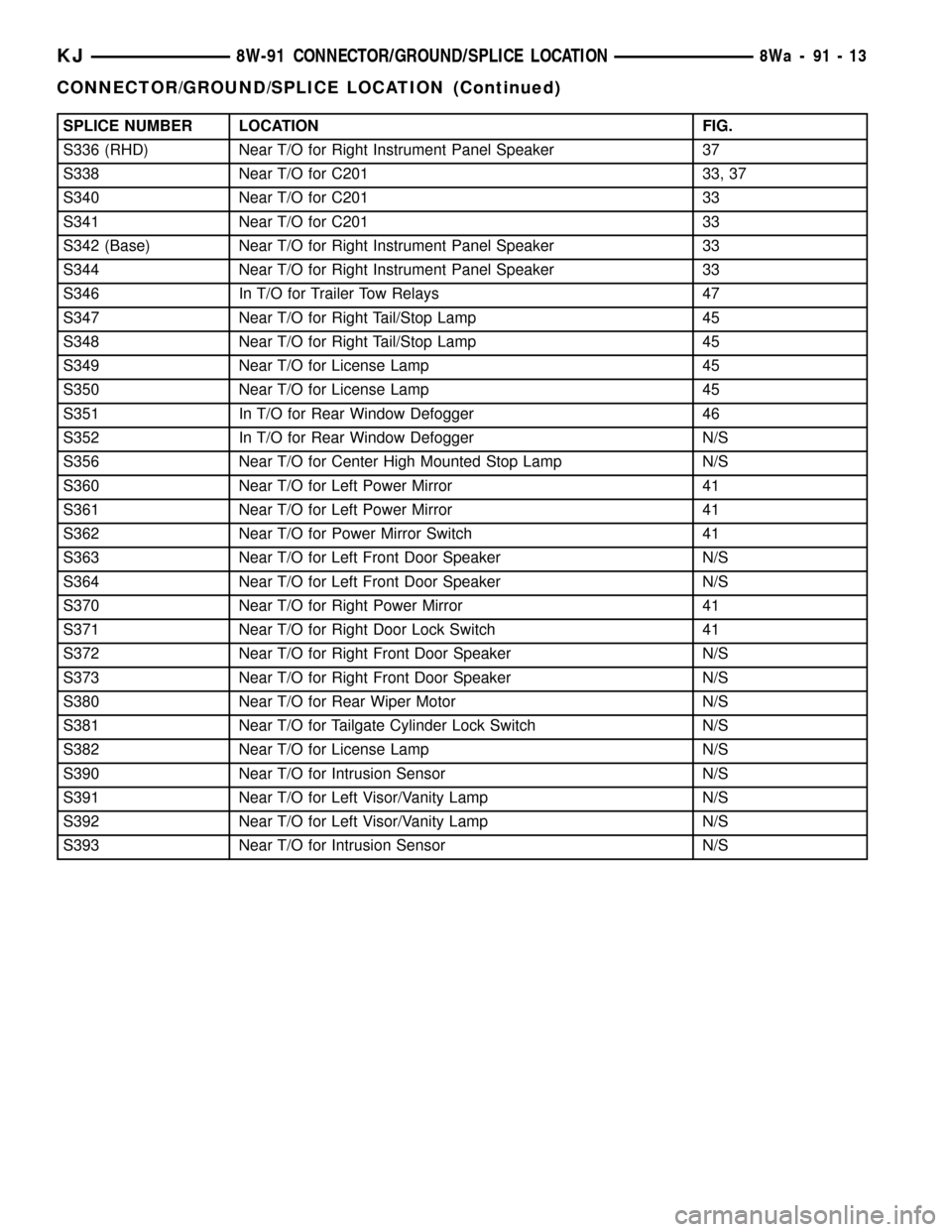
SPLICE NUMBER LOCATION FIG.
S336 (RHD) Near T/O for Right Instrument Panel Speaker 37
S338 Near T/O for C201 33, 37
S340 Near T/O for C201 33
S341 Near T/O for C201 33
S342 (Base) Near T/O for Right Instrument Panel Speaker 33
S344 Near T/O for Right Instrument Panel Speaker 33
S346 In T/O for Trailer Tow Relays 47
S347 Near T/O for Right Tail/Stop Lamp 45
S348 Near T/O for Right Tail/Stop Lamp 45
S349 Near T/O for License Lamp 45
S350 Near T/O for License Lamp 45
S351 In T/O for Rear Window Defogger 46
S352 In T/O for Rear Window Defogger N/S
S356 Near T/O for Center High Mounted Stop Lamp N/S
S360 Near T/O for Left Power Mirror 41
S361 Near T/O for Left Power Mirror 41
S362 Near T/O for Power Mirror Switch 41
S363 Near T/O for Left Front Door Speaker N/S
S364 Near T/O for Left Front Door Speaker N/S
S370 Near T/O for Right Power Mirror 41
S371 Near T/O for Right Door Lock Switch 41
S372 Near T/O for Right Front Door Speaker N/S
S373 Near T/O for Right Front Door Speaker N/S
S380 Near T/O for Rear Wiper Motor N/S
S381 Near T/O for Tailgate Cylinder Lock Switch N/S
S382 Near T/O for License Lamp N/S
S390 Near T/O for Intrusion Sensor N/S
S391 Near T/O for Left Visor/Vanity Lamp N/S
S392 Near T/O for Left Visor/Vanity Lamp N/S
S393 Near T/O for Intrusion Sensor N/S
KJ8W-91 CONNECTOR/GROUND/SPLICE LOCATION8Wa-91-13
CONNECTOR/GROUND/SPLICE LOCATION (Continued)
Page 1407 of 1803
REMOVAL
Fuel Tank Draining
WARNING: THE FUEL SYSTEM MAY BE UNDER
CONSTANT FUEL PRESSURE EVEN WITH THE
ENGINE OFF. THIS PRESSURE MUST BE
RELEASED BEFORE SERVICING FUEL TANK.
Two different procedures may be used to drain fuel
tank: removing fuel pump module access plate, or
using DRBtscan tool. Due to a one-way check valve
installed into the fuel fill opening fitting at the tank
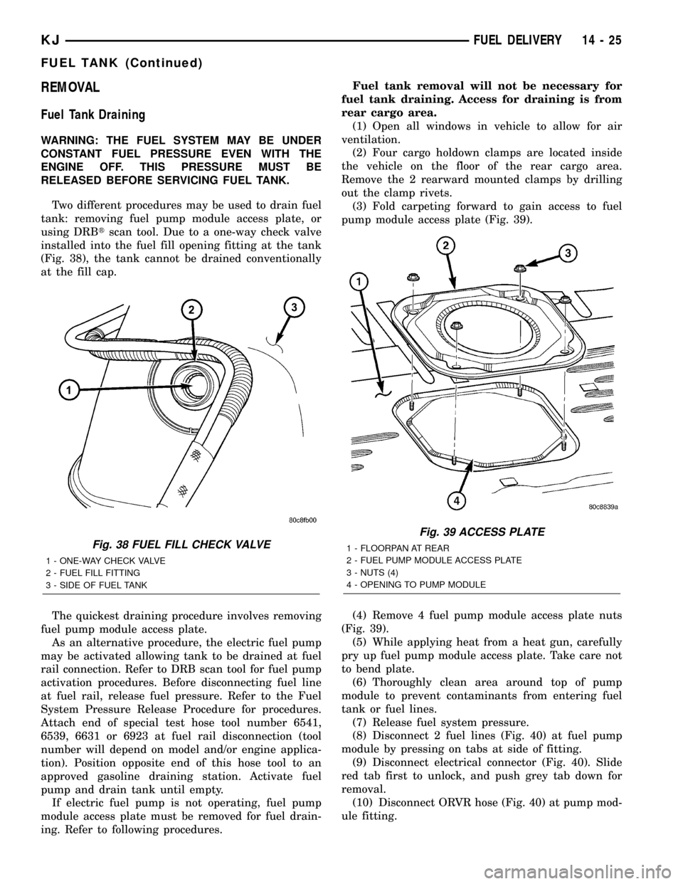
(Fig. 38), the tank cannot be drained conventionally
at the fill cap.
The quickest draining procedure involves removing
fuel pump module access plate.
As an alternative procedure, the electric fuel pump
may be activated allowing tank to be drained at fuel
rail connection. Refer to DRB scan tool for fuel pump
activation procedures. Before disconnecting fuel line
at fuel rail, release fuel pressure. Refer to the Fuel
System Pressure Release Procedure for procedures.
Attach end of special test hose tool number 6541,
6539, 6631 or 6923 at fuel rail disconnection (tool
number will depend on model and/or engine applica-
tion). Position opposite end of this hose tool to an
approved gasoline draining station. Activate fuel
pump and drain tank until empty.
If electric fuel pump is not operating, fuel pump
module access plate must be removed for fuel drain-
ing. Refer to following procedures.Fuel tank removal will not be necessary for
fuel tank draining. Access for draining is from
rear cargo area.
(1) Open all windows in vehicle to allow for air
ventilation.
(2) Four cargo holdown clamps are located inside
the vehicle on the floor of the rear cargo area.
Remove the 2 rearward mounted clamps by drilling
out the clamp rivets.
(3) Fold carpeting forward to gain access to fuel
pump module access plate (Fig. 39).
(4) Remove 4 fuel pump module access plate nuts
(Fig. 39).
(5) While applying heat from a heat gun, carefully
pry up fuel pump module access plate. Take care not
to bend plate.
(6) Thoroughly clean area around top of pump
module to prevent contaminants from entering fuel
tank or fuel lines.
(7) Release fuel system pressure.
(8) Disconnect 2 fuel lines (Fig. 40) at fuel pump
module by pressing on tabs at side of fitting.
(9) Disconnect electrical connector (Fig. 40). Slide
red tab first to unlock, and push grey tab down for
removal.
(10) Disconnect ORVR hose (Fig. 40) at pump mod-
ule fitting.
Fig. 38 FUEL FILL CHECK VALVE
1 - ONE-WAY CHECK VALVE
2 - FUEL FILL FITTING
3 - SIDE OF FUEL TANK
Fig. 39 ACCESS PLATE
1 - FLOORPAN AT REAR
2 - FUEL PUMP MODULE ACCESS PLATE
3 - NUTS (4)
4 - OPENING TO PUMP MODULE
KJFUEL DELIVERY 14 - 25
FUEL TANK (Continued)
Page 1588 of 1803
EXTERIOR HANDLE
REMOVAL
(1) Remove the door glass. (Refer to 23 - BODY/
DOOR - FRONT/DOOR GLASS - REMOVAL)
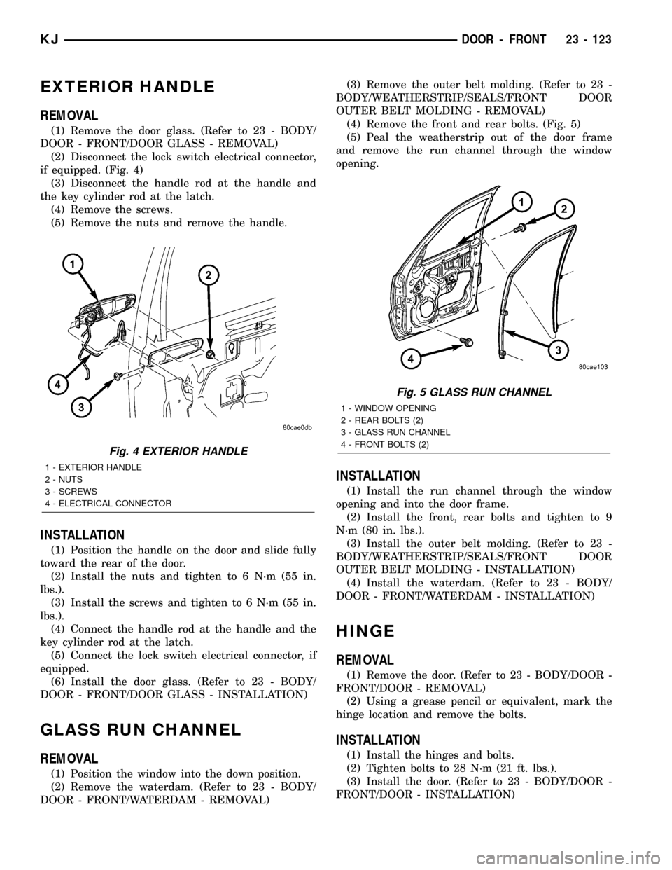
(2) Disconnect the lock switch electrical connector,
if equipped. (Fig. 4)
(3) Disconnect the handle rod at the handle and
the key cylinder rod at the latch.
(4) Remove the screws.
(5) Remove the nuts and remove the handle.
INSTALLATION
(1) Position the handle on the door and slide fully
toward the rear of the door.
(2) Install the nuts and tighten to 6 N´m (55 in.
lbs.).
(3) Install the screws and tighten to 6 N´m (55 in.
lbs.).
(4) Connect the handle rod at the handle and the
key cylinder rod at the latch.
(5) Connect the lock switch electrical connector, if
equipped.
(6) Install the door glass. (Refer to 23 - BODY/
DOOR - FRONT/DOOR GLASS - INSTALLATION)
GLASS RUN CHANNEL
REMOVAL
(1) Position the window into the down position.
(2) Remove the waterdam. (Refer to 23 - BODY/
DOOR - FRONT/WATERDAM - REMOVAL)(3) Remove the outer belt molding. (Refer to 23 -
BODY/WEATHERSTRIP/SEALS/FRONT DOOR
OUTER BELT MOLDING - REMOVAL)
(4) Remove the front and rear bolts. (Fig. 5)
(5) Peal the weatherstrip out of the door frame
and remove the run channel through the window
opening.
INSTALLATION
(1) Install the run channel through the window
opening and into the door frame.
(2) Install the front, rear bolts and tighten to 9
N´m (80 in. lbs.).
(3) Install the outer belt molding. (Refer to 23 -
BODY/WEATHERSTRIP/SEALS/FRONT DOOR
OUTER BELT MOLDING - INSTALLATION)
(4) Install the waterdam. (Refer to 23 - BODY/
DOOR - FRONT/WATERDAM - INSTALLATION)
HINGE
REMOVAL
(1) Remove the door. (Refer to 23 - BODY/DOOR -
FRONT/DOOR - REMOVAL)
(2) Using a grease pencil or equivalent, mark the
hinge location and remove the bolts.
INSTALLATION
(1) Install the hinges and bolts.
(2) Tighten bolts to 28 N´m (21 ft. lbs.).
(3) Install the door. (Refer to 23 - BODY/DOOR -
FRONT/DOOR - INSTALLATION)
Fig. 4 EXTERIOR HANDLE
1 - EXTERIOR HANDLE
2 - NUTS
3 - SCREWS
4 - ELECTRICAL CONNECTOR
Fig. 5 GLASS RUN CHANNEL
1 - WINDOW OPENING
2 - REAR BOLTS (2)
3 - GLASS RUN CHANNEL
4 - FRONT BOLTS (2)
KJDOOR - FRONT 23 - 123