2002 JEEP LIBERTY electric
[x] Cancel search: electricPage 1597 of 1803
LATCH STRIKER
REMOVAL
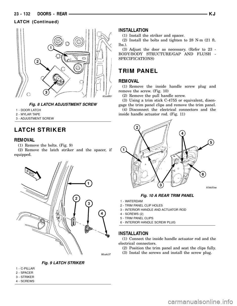
(1) Remove the bolts. (Fig. 9)
(2) Remove the latch striker and the spacer, if
equipped.
INSTALLATION
(1) Install the striker and spacer.
(2) Install the bolts and tighten to 28 N´m (21 ft.
lbs.).
(3) Adjust the door as necessary. (Refer to 23 -
BODY/BODY STRUCTURE/GAP AND FLUSH -
SPECIFICATIONS)
TRIM PANEL
REMOVAL
(1) Remove the inside handle screw plug and
remove the screw. (Fig. 10)
(2) Remove the pull handle screw.
(3) Using a trim stick C-4755 or equivalent, disen-
gage the trim panel clips and remove the trim panel.
(4) Disconnect the electrical connectors and the
inside handle actuator rod. (Fig. 11)
INSTALLATION
(1) Connect the inside handle actuator rod and the
electrical connectors.
(2) Position the trim panel and seat the clips fully.
(3) Instal the screws and install the screw plug.
Fig. 8 LATCH ADJUSTMENT SCREW
1 - DOOR LATCH
2 - MYLAR TAPE
3 - ADJUSTMENT SCREW
Fig. 9 LATCH STRIKER
1 - C-PILLAR
2 - SPACER
3 - STRIKER
4 - SCREWS
Fig. 10 A REAR TRIM PANEL
1 - WATERDAM
2 - TRIM PANEL CLIP HOLES
3 - INTERIOR HANDLE AND ACTUATOR ROD
4 - SCREWS (2)
5 - TRIM PANEL CLIPS
6 - INTERIOR HANDLE SCREW PLUG
23 - 132 DOORS - REARKJ
LATCH (Continued)
Page 1599 of 1803
(3) Install the runout tube clip.
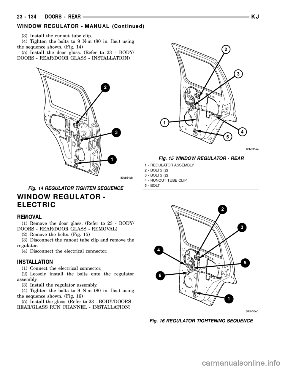
(4) Tighten the bolts to 9 N´m (80 in. lbs.) using
the sequence shown. (Fig. 14)
(5) Install the door glass. (Refer to 23 - BODY/
DOORS - REAR/DOOR GLASS - INSTALLATION)
WINDOW REGULATOR -
ELECTRIC
REMOVAL
(1) Remove the door glass. (Refer to 23 - BODY/
DOORS - REAR/DOOR GLASS - REMOVAL)
(2) Remove the bolts. (Fig. 15)
(3) Disconnect the runout tube clip and remove the
regulator.
(4) Disconnect the electrical connector.
INSTALLATION
(1) Connect the electrical connector.
(2) Loosely install the bolts onto the regulator
assembly.
(3) Install the regulator assembly.
(4) Tighten the bolts to 9 N´m (80 in. lbs.) using
the sequence shown. (Fig. 16)
(5) Install the glass. (Refer to 23 - BODY/DOORS -
REAR/GLASS RUN CHANNEL - INSTALLATION)
Fig. 14 REGULATOR TIGHTEN SEQUENCE
Fig. 15 WINDOW REGULATOR - REAR
1 - REGULATOR ASSEMBLY
2 - BOLTS (2)
3 - BOLTS (2)
4 - RUNOUT TUBE CLIP
5 - BOLT
Fig. 16 REGULATOR TIGHTENING SEQUENCE
23 - 134 DOORS - REARKJ
WINDOW REGULATOR - MANUAL (Continued)
Page 1601 of 1803
EXTERIOR HANDLE
REMOVAL
(1) Remove the trim panel and waterdam. (Refer
to 23 - BODY/SWING GATE/TRIM PANEL -
REMOVAL)
(2) Disconnect the lock switch and flip-up glass
release electrical connectors.
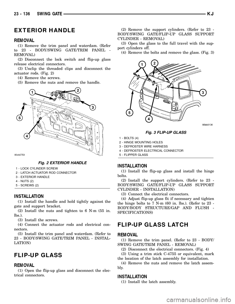
(3) Unclip the threaded clips and disconnect the
actuator rods. (Fig. 2)
(4) Remove the screws.
(5) Remove the nuts and remove the handle.
INSTALLATION
(1) Install the handle and hold tightly against the
gate and support bracket.
(2) Install the nuts and tighten to 6 N´m (55 in.
lbs.).
(3) Install the screws.
(4) Connect the actuator rods and electrical con-
nectors.
(5) Install the trim panel and waterdam. (Refer to
23 - BODY/SWING GATE/TRIM PANEL - INSTAL-
LATION)
FLIP-UP GLASS
REMOVAL
(1) Open the flip-up glass and disconnect the elec-
trical connectors.(2) Remove the support cylinders. (Refer to 23 -
BODY/SWING GATE/FLIP-UP GLASS SUPPORT
CYLINDER - REMOVAL)
(3) Open the glass to the full travel with the sup-
port cylinders off.
(4) Remove the bolts and remove the glass. (Fig. 3)
INSTALLATION
(1) Install the flip-up glass and install the hinge
bolts.
(2) Install the support cylinders. (Refer to 23 -
BODY/SWING GATE/FLIP-UP GLASS SUPPORT
CYLINDER - INSTALLATION)
(3) Connect the electrical connectors.
(4) Adjust flip-up glass fit if necessary and tighten
the hinge bolts to 7 N´m (60 in. lbs.). (Refer to 23 -
BODY/BODY STRUCTURE/GAP AND FLUSH -
SPECIFICATIONS)
FLIP-UP GLASS LATCH
REMOVAL
(1) Remove the trim panel. (Refer to 23 - BODY/
SWING GATE/TRIM PANEL - REMOVAL)
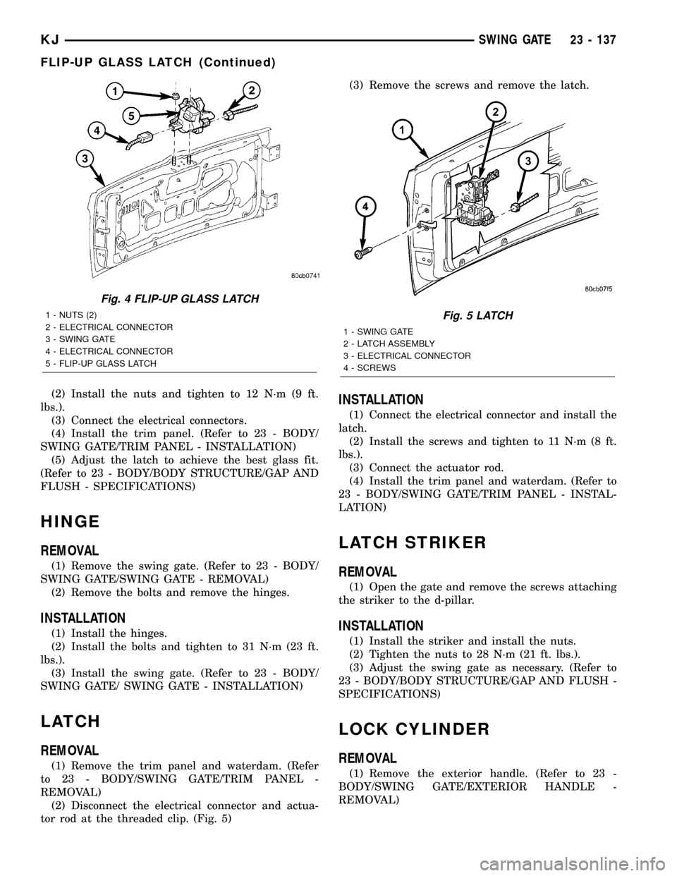
(2) Disconnect the electrical connectors. (Fig. 4)
(3) Using a trim stick C-4755 or equivalent, mark
the location of the latch assembly for installation.
(4) Remove the nuts and remove the latch assem-
bly.
INSTALLATION
(1) Install the latch assembly.
Fig. 2 EXTERIOR HANDLE
1 - LOCK CYLINDER SCREW
2 - LATCH ACTUATOR ROD CONNECTOR
3 - EXTERIOR HANDLE
4 - NUTS (2)
5 - SCREWS (2)
Fig. 3 FLIP-UP GLASS
1 - BOLTS (4)
2 - HINGE MOUNTING HOLES
3 - DEFROSTER WIRE HARNESS
4 - DEFROSTER ELECTRICAL CONNECTOR
5 - FLIPPER GLASS
23 - 136 SWING GATEKJ
Page 1602 of 1803
(2) Install the nuts and tighten to 12 N´m (9 ft.
lbs.).
(3) Connect the electrical connectors.
(4) Install the trim panel. (Refer to 23 - BODY/
SWING GATE/TRIM PANEL - INSTALLATION)
(5) Adjust the latch to achieve the best glass fit.
(Refer to 23 - BODY/BODY STRUCTURE/GAP AND
FLUSH - SPECIFICATIONS)
HINGE
REMOVAL
(1) Remove the swing gate. (Refer to 23 - BODY/
SWING GATE/SWING GATE - REMOVAL)
(2) Remove the bolts and remove the hinges.
INSTALLATION
(1) Install the hinges.
(2) Install the bolts and tighten to 31 N´m (23 ft.
lbs.).
(3) Install the swing gate. (Refer to 23 - BODY/
SWING GATE/ SWING GATE - INSTALLATION)
LATCH
REMOVAL
(1) Remove the trim panel and waterdam. (Refer
to 23 - BODY/SWING GATE/TRIM PANEL -
REMOVAL)
(2) Disconnect the electrical connector and actua-
tor rod at the threaded clip. (Fig. 5)(3) Remove the screws and remove the latch.
INSTALLATION
(1) Connect the electrical connector and install the
latch.
(2) Install the screws and tighten to 11 N´m (8 ft.
lbs.).
(3) Connect the actuator rod.
(4) Install the trim panel and waterdam. (Refer to
23 - BODY/SWING GATE/TRIM PANEL - INSTAL-
LATION)
LATCH STRIKER
REMOVAL
(1) Open the gate and remove the screws attaching
the striker to the d-pillar.
INSTALLATION
(1) Install the striker and install the nuts.
(2) Tighten the nuts to 28 N´m (21 ft. lbs.).
(3) Adjust the swing gate as necessary. (Refer to
23 - BODY/BODY STRUCTURE/GAP AND FLUSH -
SPECIFICATIONS)
LOCK CYLINDER
REMOVAL
(1) Remove the exterior handle. (Refer to 23 -
BODY/SWING GATE/EXTERIOR HANDLE -
REMOVAL)
Fig. 4 FLIP-UP GLASS LATCH
1 - NUTS (2)
2 - ELECTRICAL CONNECTOR
3 - SWING GATE
4 - ELECTRICAL CONNECTOR
5 - FLIP-UP GLASS LATCHFig. 5 LATCH
1 - SWING GATE
2 - LATCH ASSEMBLY
3 - ELECTRICAL CONNECTOR
4 - SCREWS
KJSWING GATE 23 - 137
FLIP-UP GLASS LATCH (Continued)
Page 1603 of 1803
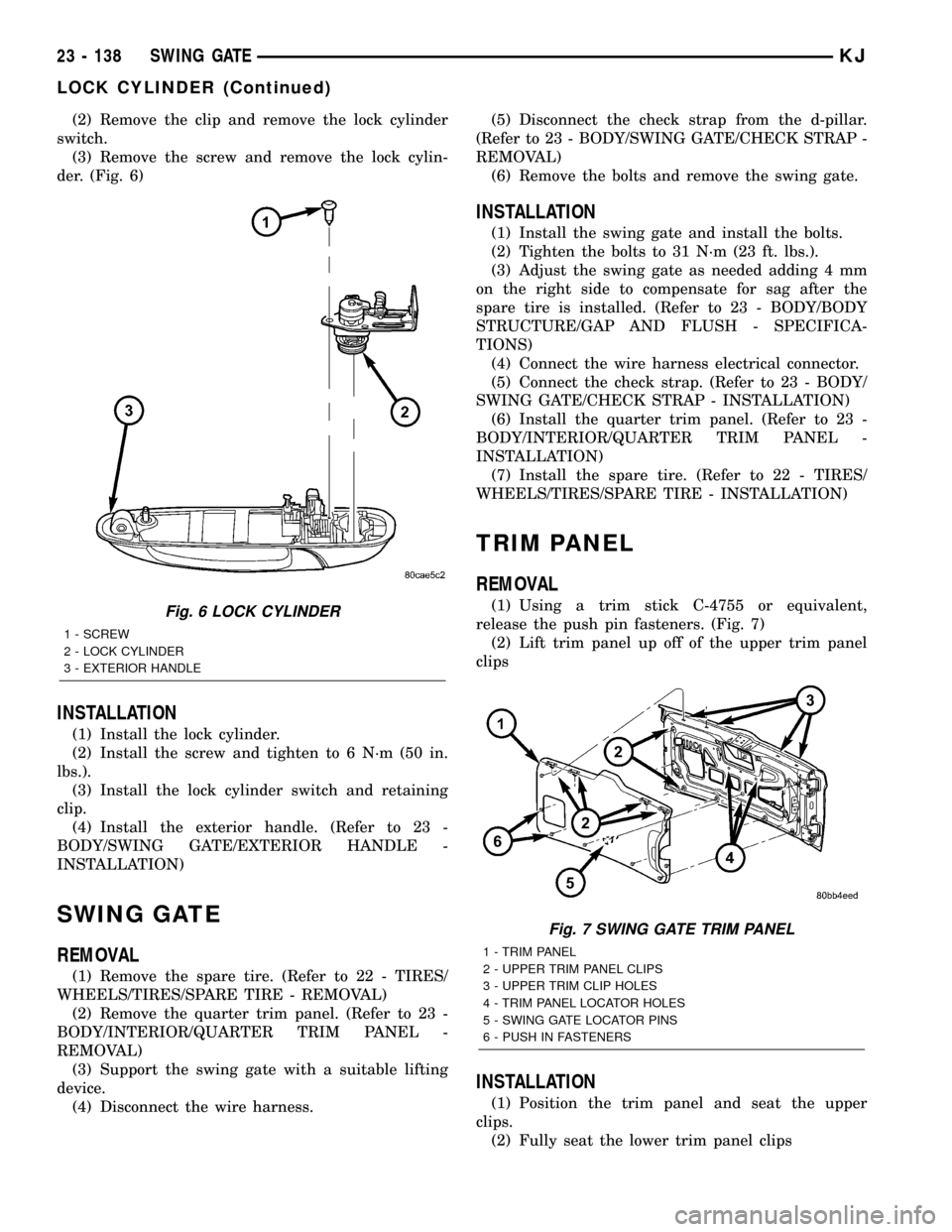
(2) Remove the clip and remove the lock cylinder
switch.
(3) Remove the screw and remove the lock cylin-
der. (Fig. 6)
INSTALLATION
(1) Install the lock cylinder.
(2) Install the screw and tighten to 6 N´m (50 in.
lbs.).
(3) Install the lock cylinder switch and retaining
clip.
(4) Install the exterior handle. (Refer to 23 -
BODY/SWING GATE/EXTERIOR HANDLE -
INSTALLATION)
SWING GATE
REMOVAL
(1) Remove the spare tire. (Refer to 22 - TIRES/
WHEELS/TIRES/SPARE TIRE - REMOVAL)
(2) Remove the quarter trim panel. (Refer to 23 -
BODY/INTERIOR/QUARTER TRIM PANEL -
REMOVAL)
(3) Support the swing gate with a suitable lifting
device.
(4) Disconnect the wire harness.(5) Disconnect the check strap from the d-pillar.
(Refer to 23 - BODY/SWING GATE/CHECK STRAP -
REMOVAL)
(6) Remove the bolts and remove the swing gate.
INSTALLATION
(1) Install the swing gate and install the bolts.
(2) Tighten the bolts to 31 N´m (23 ft. lbs.).
(3) Adjust the swing gate as needed adding 4 mm
on the right side to compensate for sag after the
spare tire is installed. (Refer to 23 - BODY/BODY
STRUCTURE/GAP AND FLUSH - SPECIFICA-
TIONS)
(4) Connect the wire harness electrical connector.
(5) Connect the check strap. (Refer to 23 - BODY/
SWING GATE/CHECK STRAP - INSTALLATION)
(6) Install the quarter trim panel. (Refer to 23 -
BODY/INTERIOR/QUARTER TRIM PANEL -
INSTALLATION)
(7) Install the spare tire. (Refer to 22 - TIRES/
WHEELS/TIRES/SPARE TIRE - INSTALLATION)
TRIM PANEL
REMOVAL
(1) Using a trim stick C-4755 or equivalent,
release the push pin fasteners. (Fig. 7)
(2) Lift trim panel up off of the upper trim panel
clips
INSTALLATION
(1) Position the trim panel and seat the upper
clips.
(2) Fully seat the lower trim panel clips
Fig. 6 LOCK CYLINDER
1 - SCREW
2 - LOCK CYLINDER
3 - EXTERIOR HANDLE
Fig. 7 SWING GATE TRIM PANEL
1 - TRIM PANEL
2 - UPPER TRIM PANEL CLIPS
3 - UPPER TRIM CLIP HOLES
4 - TRIM PANEL LOCATOR HOLES
5 - SWING GATE LOCATOR PINS
6 - PUSH IN FASTENERS
23 - 138 SWING GATEKJ
LOCK CYLINDER (Continued)
Page 1607 of 1803
(2) Install the three screws.
(3) Install the fuel cap.
GRILLE
REMOVAL
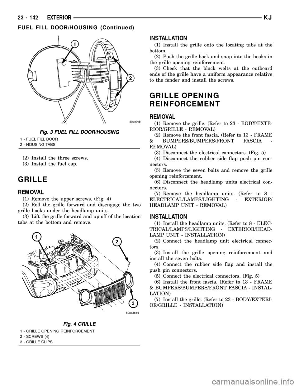
(1) Remove the upper screws. (Fig. 4)
(2) Roll the grille forward and disengage the two
grille hooks under the headlamp units.
(3) Lift the grille forward and up off of the location
tabs at the bottom and remove.
INSTALLATION
(1) Install the grille onto the locating tabs at the
bottom.
(2) Push the grille back and snap into the hooks in
the grille opening reinforcement.
(3) Check that the black welts at the outboard
ends of the grille have a uniform appearance relative
to the fender and install the screws.
GRILLE OPENING
REINFORCEMENT
REMOVAL
(1) Remove the grille. (Refer to 23 - BODY/EXTE-
RIOR/GRILLE - REMOVAL)
(2) Remove the front fascia. (Refer to 13 - FRAME
& BUMPERS/BUMPERS/FRONT FASCIA -
REMOVAL)
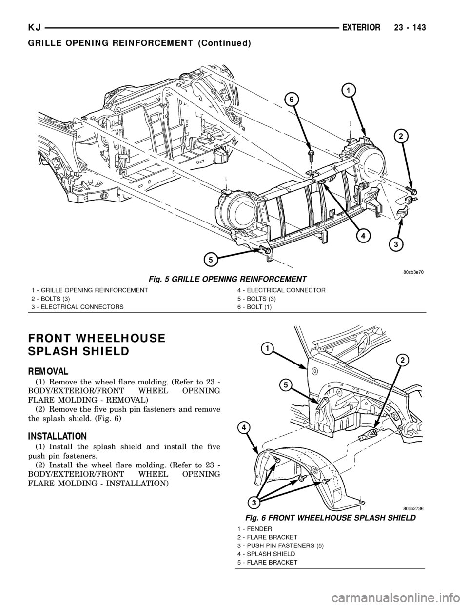
(3) Disconnect the electrical connectors. (Fig. 5)
(4) Disconnect the rubber side flap push pin con-
nectors.
(5) Remove the seven bolts and remove the grille
opening reinforcement.
(6) Disconnect the headlamp units electrical con-
nectors.
(7) Remove the headlamp units. (Refer to 8 -
ELECTRICAL/LAMPS/LIGHTING - EXTERIOR/
HEADLAMP UNIT - REMOVAL)
INSTALLATION
(1) Install the headlamp units. (Refer to 8 - ELEC-
TRICAL/LAMPS/LIGHTING - EXTERIOR/HEAD-
LAMP UNIT - INSTALLATION)
(2) Connect the headlamp unit electrical connec-
tors.
(3) Install the grille opening reinforcement and
install the seven bolts.
(4) Connect the rubber side flap and install the
push pin connectors.
(5) Connect the electrical connectors. (Fig. 5)
(6) Install the front fascia. (Refer to 13 - FRAME
& BUMPERS/BUMPERS/FRONT FASCIA - INSTAL-
LATION)
(7) Install the grille. (Refer to 23 - BODY/EXTERI-
OR/GRILLE - INSTALLATION)
Fig. 3 FUEL FILL DOOR/HOUSING
1 - FUEL FILL DOOR
2 - HOUSING TABS
Fig. 4 GRILLE
1 - GRILLE OPENING REINFORCEMENT
2 - SCREWS (4)
3 - GRILLE CLIPS
23 - 142 EXTERIORKJ
FUEL FILL DOOR/HOUSING (Continued)
Page 1608 of 1803
FRONT WHEELHOUSE
SPLASH SHIELD
REMOVAL
(1) Remove the wheel flare molding. (Refer to 23 -
BODY/EXTERIOR/FRONT WHEEL OPENING
FLARE MOLDING - REMOVAL)
(2) Remove the five push pin fasteners and remove
the splash shield. (Fig. 6)
INSTALLATION
(1) Install the splash shield and install the five
push pin fasteners.
(2) Install the wheel flare molding. (Refer to 23 -
BODY/EXTERIOR/FRONT WHEEL OPENING
FLARE MOLDING - INSTALLATION)
Fig. 5 GRILLE OPENING REINFORCEMENT
1 - GRILLE OPENING REINFORCEMENT
2 - BOLTS (3)
3 - ELECTRICAL CONNECTORS4 - ELECTRICAL CONNECTOR
5 - BOLTS (3)
6 - BOLT (1)
Fig. 6 FRONT WHEELHOUSE SPLASH SHIELD
1 - FENDER
2 - FLARE BRACKET
3 - PUSH PIN FASTENERS (5)
4 - SPLASH SHIELD
5 - FLARE BRACKET
KJEXTERIOR 23 - 143
GRILLE OPENING REINFORCEMENT (Continued)
Page 1610 of 1803
SIDE VIEW MIRROR
REMOVAL
(1) Remove the trim panel. (Refer to 23 - BODY/
DOOR - FRONT/TRIM PANEL - REMOVAL)
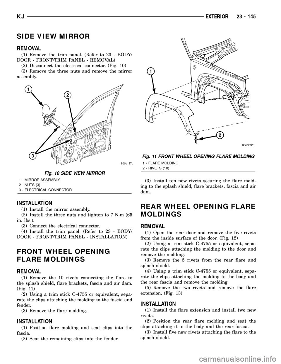
(2) Disconnect the electrical connector. (Fig. 10)
(3) Remove the three nuts and remove the mirror
assembly.
INSTALLATION
(1) Install the mirror assembly.
(2) Install the three nuts and tighten to 7 N´m (65
in. lbs.).
(3) Connect the electrical connector.
(4) Install the trim panel. (Refer to 23 - BODY/
DOOR - FRONT/TRIM PANEL - INSTALLATION)
FRONT WHEEL OPENING
FLARE MOLDINGS
REMOVAL
(1) Remove the 10 rivets connecting the flare to
the splash shield, flare brackets, fascia and air dam.
(Fig. 11)
(2) Using a trim stick C-4755 or equivalent, sepa-
rate the clips attaching the molding to the fascia and
fender.
(3) Remove the flare molding.
INSTALLATION
(1) Position flare molding and seat clips into the
fascia.
(2) Seat the remaining clips into the fender.(3) Install ten new rivets securing the flare mold-
ing to the splash shield, flare brackets, fascia and air
dam.
REAR WHEEL OPENING FLARE
MOLDINGS
REMOVAL
(1) Open the rear door and remove the five rivets
from the inside surface of the door. (Fig. 12)
(2) Using a trim stick C-4755 or equivalent, sepa-
rate the clips attaching the molding to the door and
remove the molding.
(3) Remove the 5 rivets from the rear flare and
splash shield.
(4) Using a trim stick C-4755 or equivalent, sepa-
rate the clips attaching the molding to the body and
the rear fascia and remove the molding.
(5) Remove the two rivets and remove the flare
extension. (Fig. 13)
INSTALLATION
(1) Install the flare extension and install two new
rivets.
(2) Position the rear flare molding and seat the
clips attaching it to the body and the rear fascia.
(3) Install five new rivets attaching the flare to the
splash shield.
Fig. 10 SIDE VIEW MIRROR
1 - MIRROR ASSEMBLY
2 - NUTS (3)
3 - ELECTRICAL CONNECTOR
Fig. 11 FRONT WHEEL OPENING FLARE MOLDING
1 - FLARE MOLDING
2 - RIVETS (10)
KJEXTERIOR 23 - 145