2002 JEEP LIBERTY 9 Engine
[x] Cancel search: 9 EnginePage 1286 of 1803
(1) Position the engine exhaust manifold and gas-
ket on the two studs located on the cylinder head.
Install conical washers and nuts on these studs.
(2) Install remaining conical washers. Starting at
the center arm and working outward, tighten the
bolts and nuts to 25 N´m (18 ft. lbs.) torque.
(3) Install the exhaust heat shields.
(4) Raise and support the vehicle.
CAUTION: Over tightening heat shield fasteners,
may cause shield to distort and/or crack.
(5) Assemble exhaust pipe to manifold and secure
with bolts, nuts and retainers. Tighten the bolts and
nuts to 34 N´m (25 ft. lbs.) torque.
LEFT EXHAUST MANIFOLD
CAUTION: If the studs came out with the nuts when
removing the engine exhaust manifold, install new
studs. Apply sealer on the coarse thread ends.
Water leaks may develop at the studs if this precau-
tion is not taken.
(1) Position the engine exhaust manifold and gas-
ket on the two studs located on the cylinder head.
Install conical washers and nuts on these studs.
(2) Install remaining conical washers. Starting at
the center arm and working outward, tighten the
bolts and nuts to 25 N´m (18 ft. lbs.) torque.
(3) Install the exhaust heat shields.
(4) Raise and support the vehicle.
CAUTION: Over tightening heat shield fasteners,
may cause shield to distort and/or crack.
(5) Assemble exhaust pipe to manifold and secure
with bolts, nuts and retainers. Tighten the bolts and
nuts to 34 N´m (25 ft. lbs.) torque.
VALVE TIMING
DESCRIPTION
The timing drive system has been designed to pro-
vide quiet performance and reliability to support a
non-free wheelingengine. Specifically the intake
valves are non-free wheeling and can be easily dam-
aged with forceful engine rotation if camshaft-to-
crankshaft timing is incorrect. The timing drive
system consists of a primary chain, two secondary
timing chain drives and a counterbalance shaft drive.
OPERATION
The primary timing chain is a single inverted tooth
chain type. The primary chain drives the large 40
tooth idler sprocket directly from a 20 tooth crank-shaft sprocket. Primary chain motion is controlled by
a pivoting leaf spring tensioner arm and a fixed
guide. The arm and the guide both use nylon plastic
wear faces for low friction and long wear. The pri-
mary chain receives oil splash lubrication from the
secondary chain drive and designed oil pump leak-
age. The idler sprocket assembly connects the pri-
mary chain drive, secondary chain drives, and the
counterbalance shaft. The idler sprocket assembly
consists of two integral 26 tooth sprockets a 40 tooth
sprocket and a helical gear that is press-fit to the
assembly. The spline joint for the 40 tooth sprocket is
a non ± serviceable press fit anti rattle type. A spiral
ring is installed on the outboard side of the fifty
tooth sprocket to prevent spline disengagement. The
idler sprocket assembly spins on a stationary idler
shaft. The idler shaft is a light press-fit into the cyl-
inder block. A large washer on the idler shaft bolt
and the rear flange of the idler shaft are used to con-
trol sprocket thrust movement. Pressurized oil is
routed through the center of the idler shaft to pro-
vide lubrication for the two bushings used in the
idler sprocket assembly.
There are two secondary drive chains, both are
roller type, one to drive the camshaft in each SOHC
cylinder head. There are no shaft speed changes in
the secondary chain drive system. Each secondary
chain drives a 26 tooth cam sprocket directly from
the 26 tooth sprocket on the idler sprocket assembly.
A fixed chain guide and a hydraulic oil damped ten-
sioner are used to maintain tension in each second-
ary chain system. The hydraulic tensioners for the
secondary chain systems are fed pressurized oil from
oil reservoir pockets in the block. Each tensioner
incorprates a controled leak path through a device
known as a vent disc located in the nose of the piston
to manage chain loads. Each tensioner also has a
mechanical ratchet system that limits chain slack if
the tensioner piston bleeds down after engine shut
down. The tensioner arms and guides also utilize
nylon wear faces for low friction and long wear. The
secondary timing chains receive lubrication from a
small orifice in the tensioners. This orifice is pro-
tected from clogging by a fine mesh screen which is
located on the back of the hydraulic tensioners.
STANDARD PROCEDURE
MEASURING TIMING CHAIN WEAR
NOTE: This procedure must be performed with the
timing chain cover removed.
(1) Remove the timing chain cover. Refer to Timing
Chain Cover in this section for procedure.
KJENGINE - 3.7L 9 - 71
EXHAUST MANIFOLD (Continued)
Page 1287 of 1803
(2) To determine if the secondary timing chains
are worn, rotate the engine clockwise until maximum
tensioner piston extension is obtained. Measure the
distance between the secondary timing chain ten-
sioner housing and the step ledge on the piston. The
measurement at point (A) must be less than 15mm
(.5906 inches).
(3) If the measurement exceeds the specification
the secondary timing chains are worn and require
replacement. Refer to Timing Chain and Sprockets in
this section for procedure.
SERVICE PROCEDURES
TIMING VERIFICATION
CAUTION: The 3.7L is a non free-wheeling design
engine. Therefore, correct engine timing is critical.
NOTE: Components referred to as left hand or right
hand are as viewed from the drivers position inside
the vehicle.
NOTE: The blue link plates on the chains and the
dots on the camshaft drive sprockets may not line
up during the timing verification procedure. The
blue link plates are lined up with the sprocket dots
only when re-timing the complete timing drive.
Once the timing drive is rotated blue link-to-dot
alignment is no longer valid.
Engine base timing can be verified by the following
procedure:
(1) Remove the cylinder head covers. Refer to the
procedure in this section.
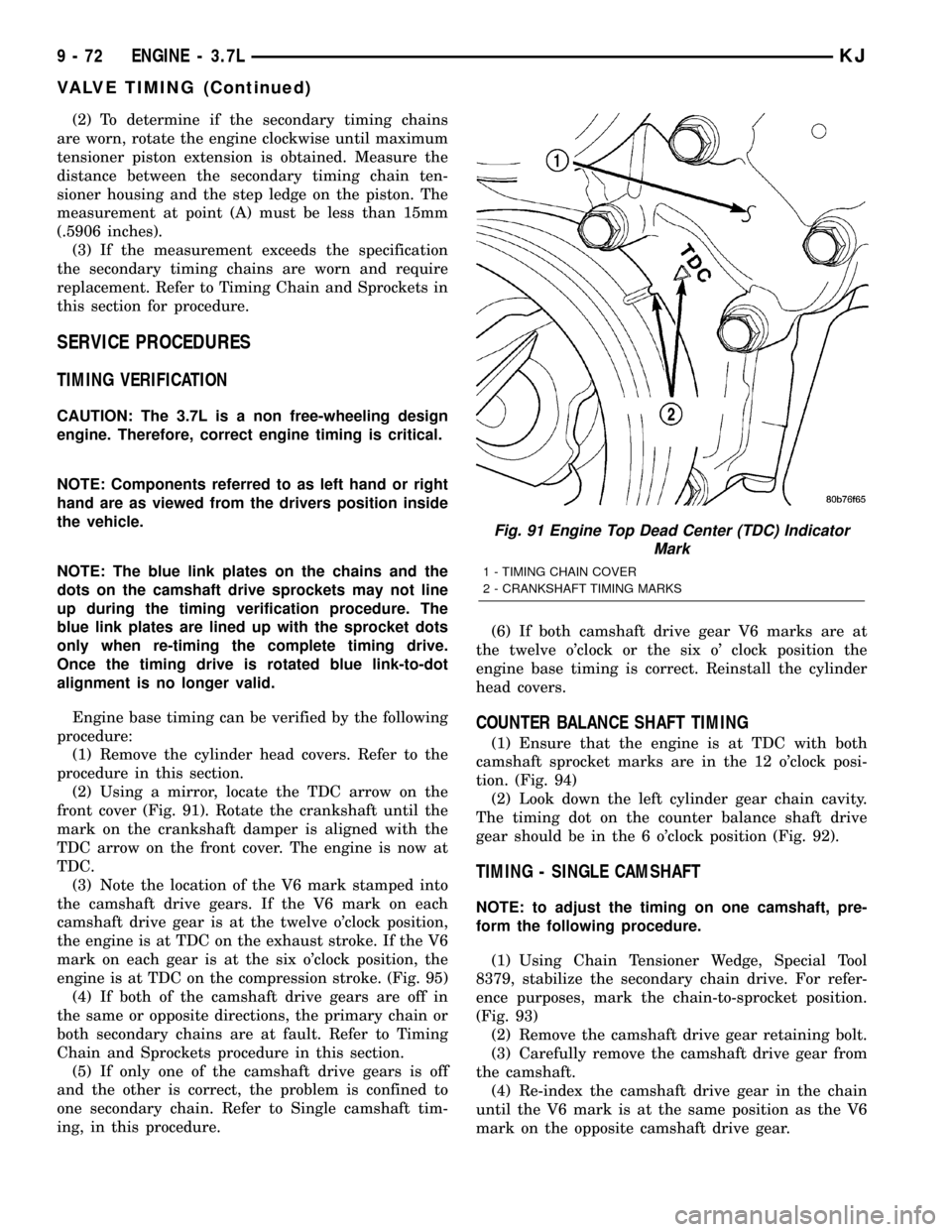
(2) Using a mirror, locate the TDC arrow on the
front cover (Fig. 91). Rotate the crankshaft until the
mark on the crankshaft damper is aligned with the
TDC arrow on the front cover. The engine is now at
TDC.
(3) Note the location of the V6 mark stamped into
the camshaft drive gears. If the V6 mark on each
camshaft drive gear is at the twelve o'clock position,
the engine is at TDC on the exhaust stroke. If the V6
mark on each gear is at the six o'clock position, the
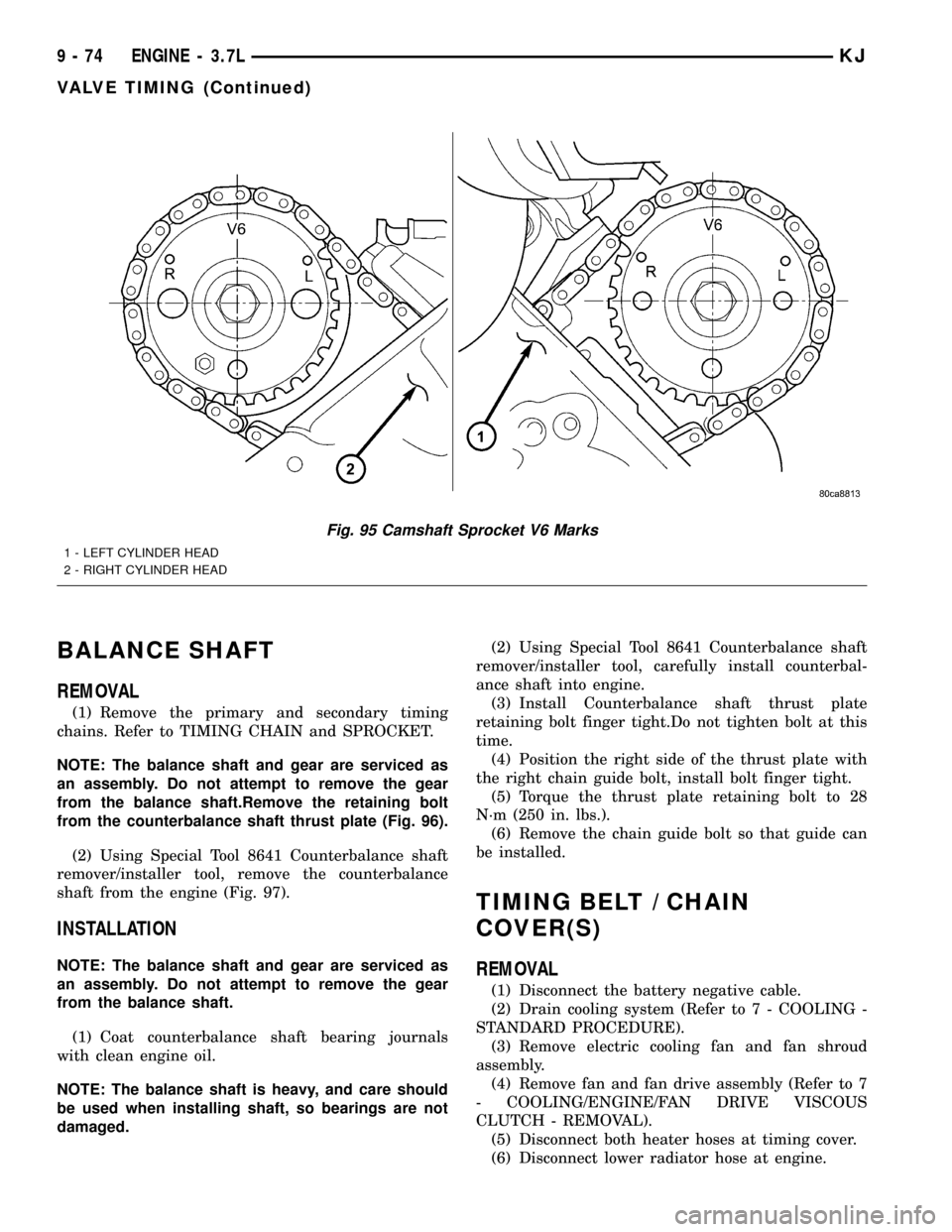
engine is at TDC on the compression stroke. (Fig. 95)
(4) If both of the camshaft drive gears are off in
the same or opposite directions, the primary chain or
both secondary chains are at fault. Refer to Timing
Chain and Sprockets procedure in this section.
(5) If only one of the camshaft drive gears is off
and the other is correct, the problem is confined to
one secondary chain. Refer to Single camshaft tim-
ing, in this procedure.(6) If both camshaft drive gear V6 marks are at
the twelve o'clock or the six o' clock position the
engine base timing is correct. Reinstall the cylinder
head covers.
COUNTER BALANCE SHAFT TIMING
(1) Ensure that the engine is at TDC with both
camshaft sprocket marks are in the 12 o'clock posi-
tion. (Fig. 94)
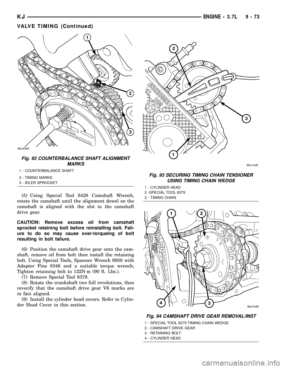
(2) Look down the left cylinder gear chain cavity.
The timing dot on the counter balance shaft drive
gear should be in the 6 o'clock position (Fig. 92).
TIMING - SINGLE CAMSHAFT
NOTE: to adjust the timing on one camshaft, pre-
form the following procedure.
(1) Using Chain Tensioner Wedge, Special Tool
8379, stabilize the secondary chain drive. For refer-
ence purposes, mark the chain-to-sprocket position.
(Fig. 93)
(2) Remove the camshaft drive gear retaining bolt.
(3) Carefully remove the camshaft drive gear from
the camshaft.
(4) Re-index the camshaft drive gear in the chain
until the V6 mark is at the same position as the V6
mark on the opposite camshaft drive gear.
Fig. 91 Engine Top Dead Center (TDC) Indicator
Mark
1 - TIMING CHAIN COVER
2 - CRANKSHAFT TIMING MARKS
9 - 72 ENGINE - 3.7LKJ
VALVE TIMING (Continued)
Page 1288 of 1803
(5) Using Special Tool 8428 Camshaft Wrench,
rotate the camshaft until the alignment dowel on the
camshaft is aligned with the slot in the camshaft
drive gear.
CAUTION: Remove excess oil from camshaft
sprocket retaining bolt before reinstalling bolt. Fail-
ure to do so may cause over-torqueing of bolt
resulting in bolt failure.
(6) Position the camshaft drive gear onto the cam-
shaft, remove oil from bolt then install the retaining
bolt. Using Special Tools, Spanner Wrench 6958 with
Adapter Pins 8346 and a suitable torque wrench,
Tighten retaining bolt to 122N´m (90 ft. Lbs.).
(7) Remove Special Tool 8379.
(8) Rotate the crankshaft two full revolutions, then
reverify that the camshaft drive gear V6 marks are
in fact aligned.
(9) Install the cylinder head covers. Refer to Cylin-
der Head Cover in this section.
Fig. 92 COUNTERBALANCE SHAFT ALIGNMENT
MARKS
1 - COUNTERBALANCE SHAFT
2 - TIMING MARKS
3 - IDLER SPROCKET
Fig. 93 SECURING TIMING CHAIN TENSIONER
USING TIMING CHAIN WEDGE
1 - CYLINDER HEAD
2 -SPECIAL TOOL 8379
2 - TIMING CHAIN
Fig. 94 CAMSHAFT DRIVE GEAR REMOVAL/INST
1 - SPECIAL TOOL 8279 TIMING CHAIN WEDGE
2 - CAMSHAFT DRIVE GEAR
3 - RETAINING BOLT
4 - CYLINDER HEAD
KJENGINE - 3.7L 9 - 73
VALVE TIMING (Continued)
Page 1289 of 1803
BALANCE SHAFT
REMOVAL
(1) Remove the primary and secondary timing
chains. Refer to TIMING CHAIN and SPROCKET.
NOTE: The balance shaft and gear are serviced as
an assembly. Do not attempt to remove the gear
from the balance shaft.Remove the retaining bolt
from the counterbalance shaft thrust plate (Fig. 96).
(2) Using Special Tool 8641 Counterbalance shaft
remover/installer tool, remove the counterbalance
shaft from the engine (Fig. 97).
INSTALLATION
NOTE: The balance shaft and gear are serviced as
an assembly. Do not attempt to remove the gear
from the balance shaft.
(1) Coat counterbalance shaft bearing journals
with clean engine oil.
NOTE: The balance shaft is heavy, and care should
be used when installing shaft, so bearings are not
damaged.(2) Using Special Tool 8641 Counterbalance shaft
remover/installer tool, carefully install counterbal-
ance shaft into engine.
(3) Install Counterbalance shaft thrust plate
retaining bolt finger tight.Do not tighten bolt at this
time.
(4) Position the right side of the thrust plate with
the right chain guide bolt, install bolt finger tight.
(5) Torque the thrust plate retaining bolt to 28
N´m (250 in. lbs.).
(6) Remove the chain guide bolt so that guide can
be installed.
TIMING BELT / CHAIN
COVER(S)
REMOVAL
(1) Disconnect the battery negative cable.
(2) Drain cooling system (Refer to 7 - COOLING -
STANDARD PROCEDURE).
(3) Remove electric cooling fan and fan shroud
assembly.
(4) Remove fan and fan drive assembly (Refer to 7
- COOLING/ENGINE/FAN DRIVE VISCOUS
CLUTCH - REMOVAL).
(5) Disconnect both heater hoses at timing cover.
(6) Disconnect lower radiator hose at engine.
Fig. 95 Camshaft Sprocket V6 Marks
1 - LEFT CYLINDER HEAD
2 - RIGHT CYLINDER HEAD
9 - 74 ENGINE - 3.7LKJ
VALVE TIMING (Continued)
Page 1290 of 1803
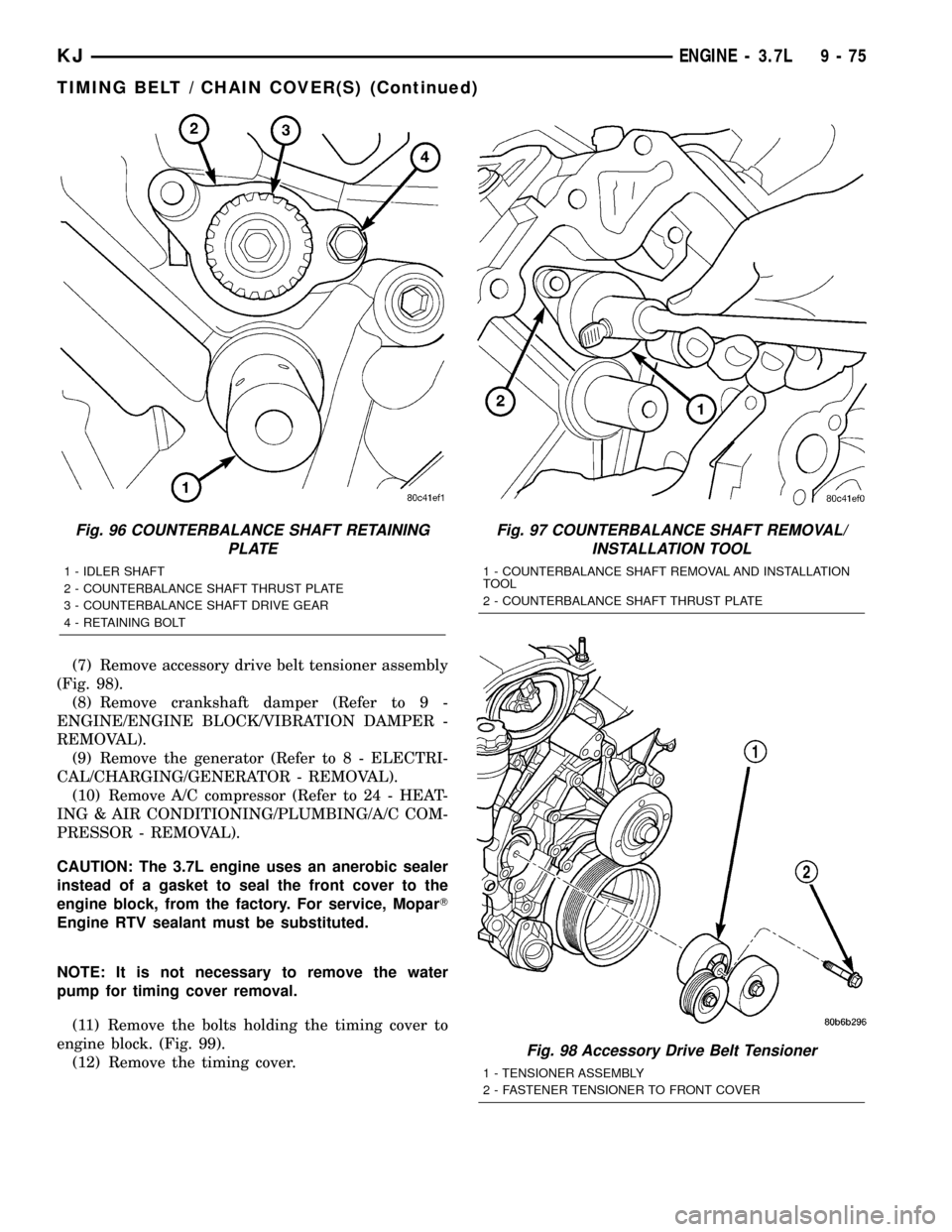
(7) Remove accessory drive belt tensioner assembly
(Fig. 98).
(8) Remove crankshaft damper (Refer to 9 -
ENGINE/ENGINE BLOCK/VIBRATION DAMPER -
REMOVAL).
(9) Remove the generator (Refer to 8 - ELECTRI-
CAL/CHARGING/GENERATOR - REMOVAL).
(10) Remove A/C compressor (Refer to 24 - HEAT-
ING & AIR CONDITIONING/PLUMBING/A/C COM-
PRESSOR - REMOVAL).
CAUTION: The 3.7L engine uses an anerobic sealer
instead of a gasket to seal the front cover to the
engine block, from the factory. For service, MoparT
Engine RTV sealant must be substituted.
NOTE: It is not necessary to remove the water
pump for timing cover removal.
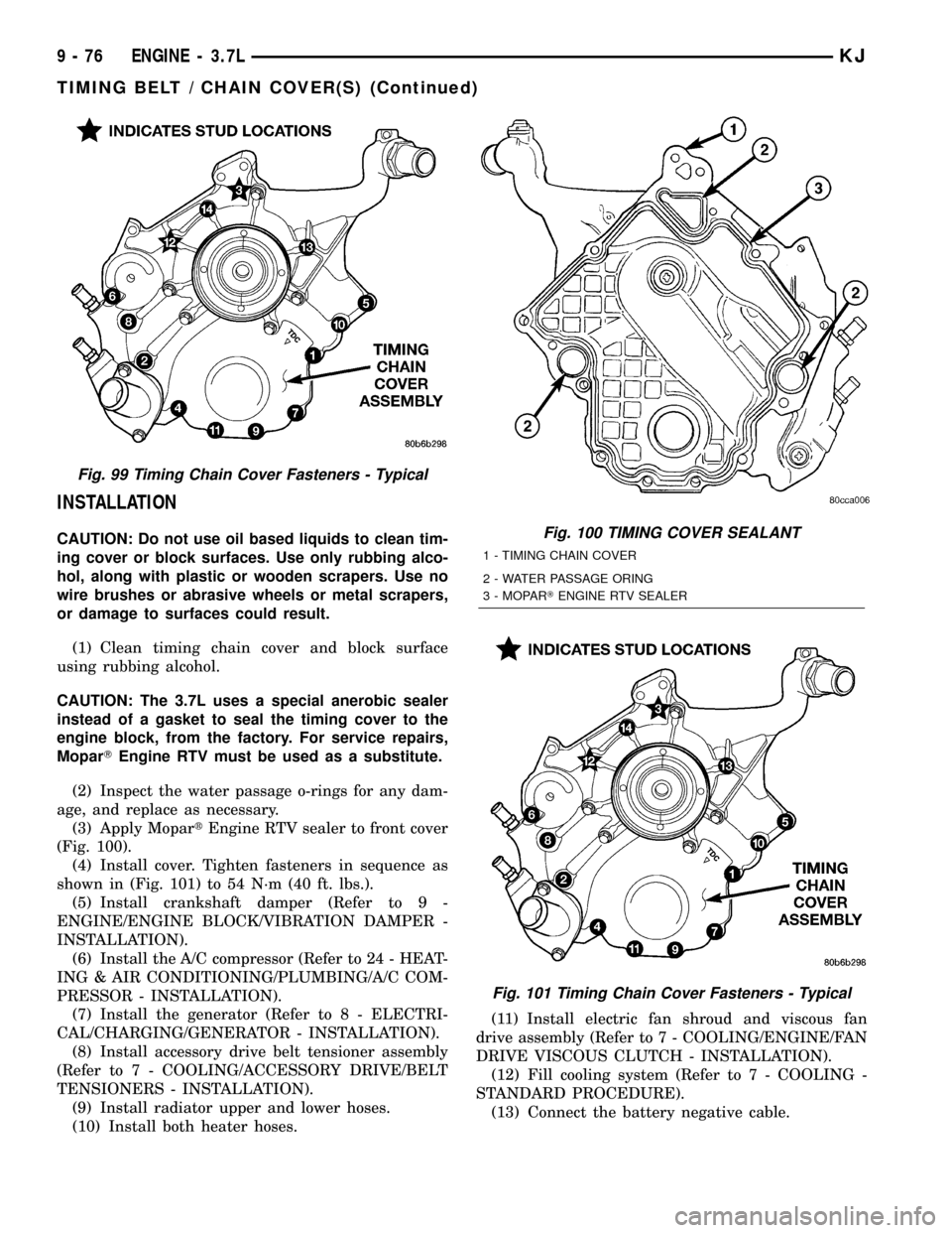
(11) Remove the bolts holding the timing cover to
engine block. (Fig. 99).
(12) Remove the timing cover.
Fig. 96 COUNTERBALANCE SHAFT RETAINING
PLATE
1 - IDLER SHAFT
2 - COUNTERBALANCE SHAFT THRUST PLATE
3 - COUNTERBALANCE SHAFT DRIVE GEAR
4 - RETAINING BOLT
Fig. 97 COUNTERBALANCE SHAFT REMOVAL/
INSTALLATION TOOL
1 - COUNTERBALANCE SHAFT REMOVAL AND INSTALLATION
TOOL
2 - COUNTERBALANCE SHAFT THRUST PLATE
Fig. 98 Accessory Drive Belt Tensioner
1 - TENSIONER ASSEMBLY
2 - FASTENER TENSIONER TO FRONT COVER
KJENGINE - 3.7L 9 - 75
TIMING BELT / CHAIN COVER(S) (Continued)
Page 1291 of 1803
INSTALLATION
CAUTION: Do not use oil based liquids to clean tim-
ing cover or block surfaces. Use only rubbing alco-
hol, along with plastic or wooden scrapers. Use no
wire brushes or abrasive wheels or metal scrapers,
or damage to surfaces could result.
(1) Clean timing chain cover and block surface
using rubbing alcohol.
CAUTION: The 3.7L uses a special anerobic sealer
instead of a gasket to seal the timing cover to the
engine block, from the factory. For service repairs,
MoparTEngine RTV must be used as a substitute.
(2) Inspect the water passage o-rings for any dam-
age, and replace as necessary.
(3) Apply MopartEngine RTV sealer to front cover
(Fig. 100).
(4) Install cover. Tighten fasteners in sequence as
shown in (Fig. 101) to 54 N´m (40 ft. lbs.).
(5) Install crankshaft damper (Refer to 9 -
ENGINE/ENGINE BLOCK/VIBRATION DAMPER -
INSTALLATION).
(6) Install the A/C compressor (Refer to 24 - HEAT-
ING & AIR CONDITIONING/PLUMBING/A/C COM-
PRESSOR - INSTALLATION).
(7) Install the generator (Refer to 8 - ELECTRI-
CAL/CHARGING/GENERATOR - INSTALLATION).
(8) Install accessory drive belt tensioner assembly
(Refer to 7 - COOLING/ACCESSORY DRIVE/BELT
TENSIONERS - INSTALLATION).
(9) Install radiator upper and lower hoses.
(10) Install both heater hoses.(11) Install electric fan shroud and viscous fan
drive assembly (Refer to 7 - COOLING/ENGINE/FAN
DRIVE VISCOUS CLUTCH - INSTALLATION).
(12) Fill cooling system (Refer to 7 - COOLING -
STANDARD PROCEDURE).
(13) Connect the battery negative cable.
Fig. 99 Timing Chain Cover Fasteners - Typical
Fig. 100 TIMING COVER SEALANT
1 - TIMING CHAIN COVER
2 - WATER PASSAGE ORING
3 - MOPARTENGINE RTV SEALER
Fig. 101 Timing Chain Cover Fasteners - Typical
9 - 76 ENGINE - 3.7LKJ
TIMING BELT / CHAIN COVER(S) (Continued)
Page 1292 of 1803
IDLER SHAFT
REMOVAL
(1) Remove the primary and secondary timing
chains and sprockets. Refer to procedure in this sec-
tion.
NOTE: To remove the idler shaft, it is necessary to
tap threads into the shaft, to install the removal
tool.
(2) Using a 12 mm X 1.75 tap, cut threads in the
idler shaft center bore.
(3) Cover the radiator core with a suitable cover.
CAUTION: Use care when removing the idler shaft,
Do not strike the radiator cooling fins with the slide
hammer.
(4) Using Special Tool 8517 Slide Hammer, remove
the idler shaft.
INSTALLATION
(1) Thoroughly clean the idler shaft bore.
(2) Position the idler shaft in the bore.
NOTE: The two lubrication holes in the idler shaft
do not require any special alignment.
NOTE: Before using the retaining bolt to install the
idler shaft, coat the threads and the pilot on the
idler shaft, with clean engine oil.
(3) Using the primary idler sprocket retaining bolt
and washer, carefully draw the idler shaft into the
bore until fully seated.
(4) Coat the idler shaft with clean engine oil.
(5) Install the timing chains and sprockets. Refer
to procedure in this section.
TIMING BELT/CHAIN AND
SPROCKET(S
REMOVAL
(1) Disconnect negative cable from battery.
(2) Drain cooling system. Refer to COOLING SYS-
TEM for procedures.
(3) Remove right and left cylinder head covers.
Refer to CYLINDER HEAD COVER.
(4) Remove radiator fan shroud. Refer to COOL-
ING SYSTEM for procedure.
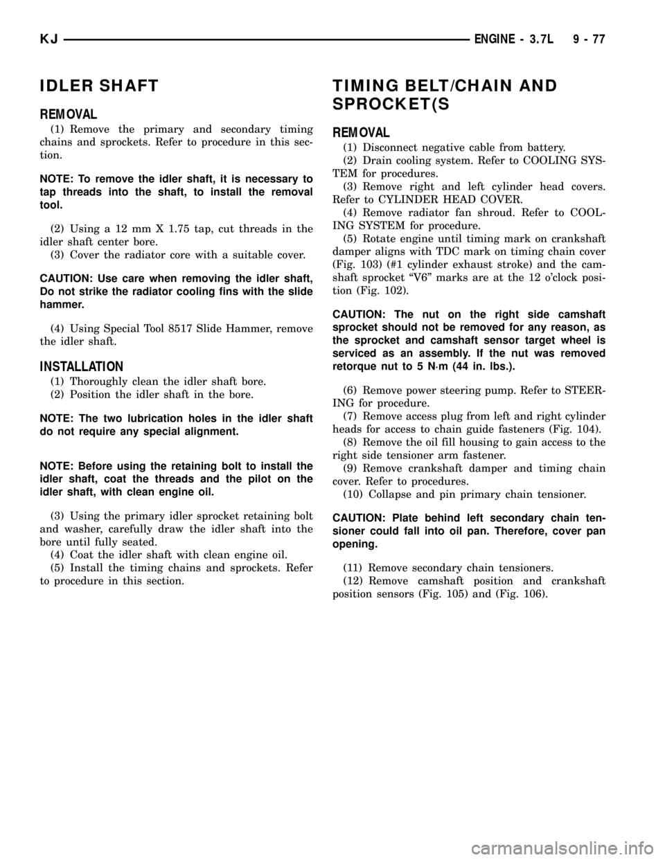
(5) Rotate engine until timing mark on crankshaft
damper aligns with TDC mark on timing chain cover
(Fig. 103) (#1 cylinder exhaust stroke) and the cam-
shaft sprocket ªV6º marks are at the 12 o'clock posi-
tion (Fig. 102).
CAUTION: The nut on the right side camshaft
sprocket should not be removed for any reason, as
the sprocket and camshaft sensor target wheel is
serviced as an assembly. If the nut was removed
retorque nut to 5 N´m (44 in. lbs.).
(6) Remove power steering pump. Refer to STEER-
ING for procedure.
(7) Remove access plug from left and right cylinder
heads for access to chain guide fasteners (Fig. 104).
(8) Remove the oil fill housing to gain access to the
right side tensioner arm fastener.
(9) Remove crankshaft damper and timing chain
cover. Refer to procedures.
(10) Collapse and pin primary chain tensioner.
CAUTION: Plate behind left secondary chain ten-
sioner could fall into oil pan. Therefore, cover pan
opening.
(11) Remove secondary chain tensioners.
(12) Remove camshaft position and crankshaft
position sensors (Fig. 105) and (Fig. 106).
KJENGINE - 3.7L 9 - 77
Page 1293 of 1803
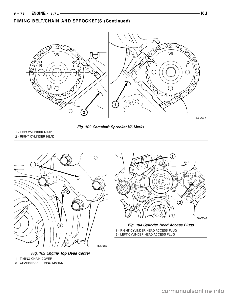
Fig. 102 Camshaft Sprocket V6 Marks
1 - LEFT CYLINDER HEAD
2 - RIGHT CYLINDER HEAD
Fig. 103 Engine Top Dead Center
1 - TIMING CHAIN COVER
2 - CRANKSHAFT TIMING MARKS
Fig. 104 Cylinder Head Access Plugs
1 - RIGHT CYLINDER HEAD ACCESS PLUG
2 - LEFT CYLINDER HEAD ACCESS PLUG
9 - 78 ENGINE - 3.7LKJ
TIMING BELT/CHAIN AND SPROCKET(S (Continued)