2002 JEEP LIBERTY 02 sensor
[x] Cancel search: 02 sensorPage 1370 of 1803
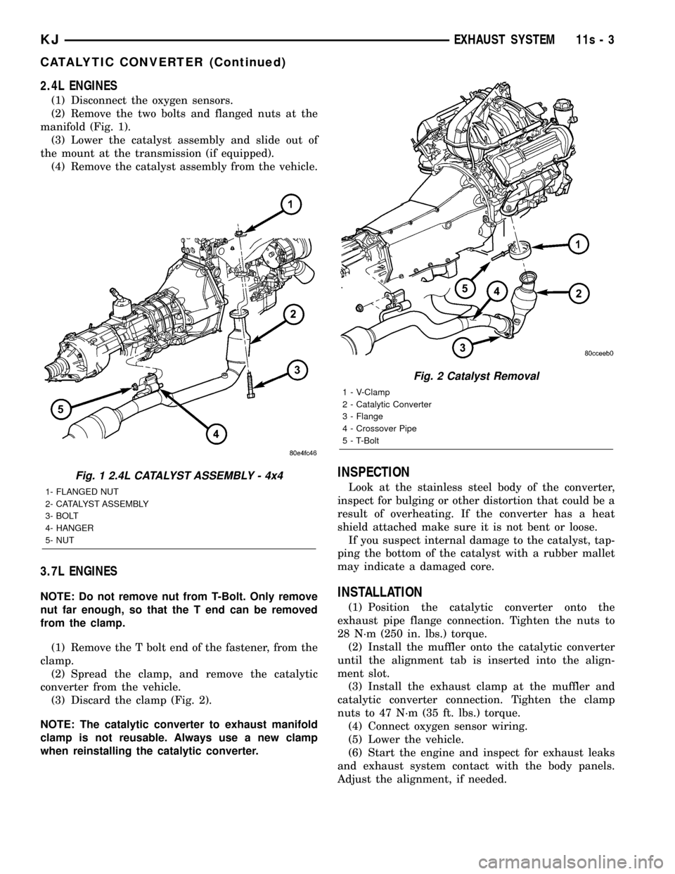
2.4L ENGINES
(1) Disconnect the oxygen sensors.
(2) Remove the two bolts and flanged nuts at the
manifold (Fig. 1).
(3) Lower the catalyst assembly and slide out of
the mount at the transmission (if equipped).
(4) Remove the catalyst assembly from the vehicle.
3.7L ENGINES
NOTE: Do not remove nut from T-Bolt. Only remove
nut far enough, so that the T end can be removed
from the clamp.
(1) Remove the T bolt end of the fastener, from the
clamp.
(2) Spread the clamp, and remove the catalytic
converter from the vehicle.
(3) Discard the clamp (Fig. 2).
NOTE: The catalytic converter to exhaust manifold
clamp is not reusable. Always use a new clamp
when reinstalling the catalytic converter.
INSPECTION
Look at the stainless steel body of the converter,
inspect for bulging or other distortion that could be a
result of overheating. If the converter has a heat
shield attached make sure it is not bent or loose.
If you suspect internal damage to the catalyst, tap-
ping the bottom of the catalyst with a rubber mallet
may indicate a damaged core.
INSTALLATION
(1) Position the catalytic converter onto the
exhaust pipe flange connection. Tighten the nuts to
28 N´m (250 in. lbs.) torque.
(2) Install the muffler onto the catalytic converter
until the alignment tab is inserted into the align-
ment slot.
(3) Install the exhaust clamp at the muffler and
catalytic converter connection. Tighten the clamp
nuts to 47 N´m (35 ft. lbs.) torque.
(4) Connect oxygen sensor wiring.
(5) Lower the vehicle.
(6) Start the engine and inspect for exhaust leaks
and exhaust system contact with the body panels.
Adjust the alignment, if needed.
Fig. 1 2.4L CATALYST ASSEMBLY - 4x4
1- FLANGED NUT
2- CATALYST ASSEMBLY
3- BOLT
4- HANGER
5- NUT
Fig. 2 Catalyst Removal
1 - V-Clamp
2 - Catalytic Converter
3 - Flange
4 - Crossover Pipe
5 - T-Bolt
KJEXHAUST SYSTEM 11s - 3
CATALYTIC CONVERTER (Continued)
Page 1372 of 1803
WARNING: IF TORCHES ARE USED WHEN WORK-
ING ON THE EXHAUST SYSTEM, DO NOT ALLOW
THE FLAME NEAR THE FUEL LINE.
CAUTION: When servicing exhaust system compo-
nents, disconnect the oxygen sensor connector.
Allowing the exhaust system to hang by the oxygen
sensor harness will damage the wiring and/or sen-
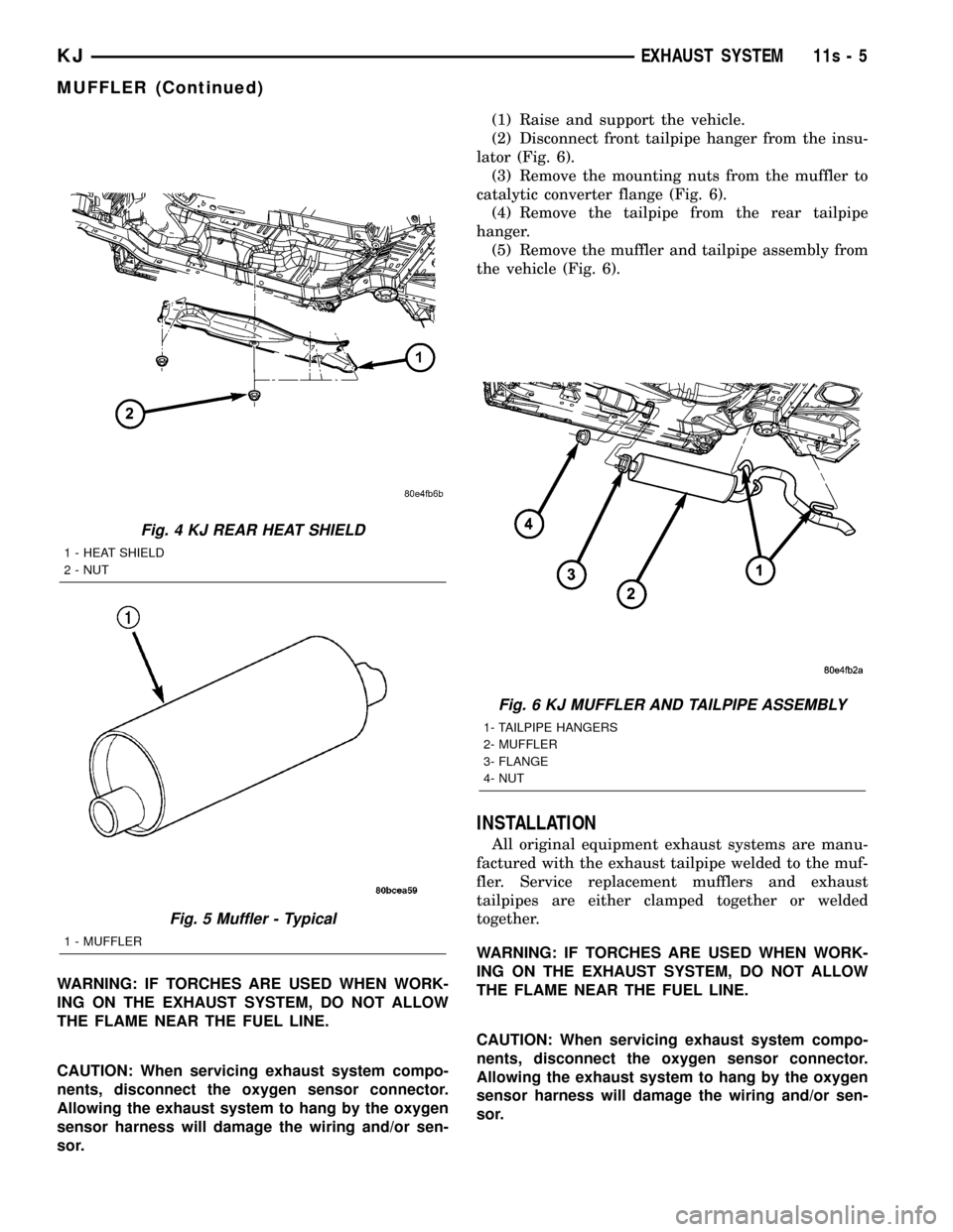
sor.(1) Raise and support the vehicle.
(2) Disconnect front tailpipe hanger from the insu-
lator (Fig. 6).
(3) Remove the mounting nuts from the muffler to
catalytic converter flange (Fig. 6).
(4) Remove the tailpipe from the rear tailpipe
hanger.
(5) Remove the muffler and tailpipe assembly from
the vehicle (Fig. 6).
INSTALLATION
All original equipment exhaust systems are manu-
factured with the exhaust tailpipe welded to the muf-
fler. Service replacement mufflers and exhaust
tailpipes are either clamped together or welded
together.
WARNING: IF TORCHES ARE USED WHEN WORK-
ING ON THE EXHAUST SYSTEM, DO NOT ALLOW
THE FLAME NEAR THE FUEL LINE.
CAUTION: When servicing exhaust system compo-
nents, disconnect the oxygen sensor connector.
Allowing the exhaust system to hang by the oxygen
sensor harness will damage the wiring and/or sen-
sor.
Fig. 4 KJ REAR HEAT SHIELD
1 - HEAT SHIELD
2 - NUT
Fig. 5 Muffler - Typical
1 - MUFFLER
Fig. 6 KJ MUFFLER AND TAILPIPE ASSEMBLY
1- TAILPIPE HANGERS
2- MUFFLER
3- FLANGE
4- NUT
KJEXHAUST SYSTEM 11s - 5
MUFFLER (Continued)
Page 1383 of 1803
FUEL SYSTEM
TABLE OF CONTENTS
page page
FUEL DELIVERY..........................1FUEL INJECTION........................29
FUEL DELIVERY
TABLE OF CONTENTS
page page
FUEL DELIVERY
DESCRIPTION..........................2
OPERATION............................3
DIAGNOSIS AND TESTING - FUEL
PRESSURE LEAK DOWN TEST...........3
STANDARD PROCEDURE - FUEL SYSTEM
PRESSURE RELEASE...................4
SPECIFICATIONS
FUEL SYSTEM PRESSURE..............5
TORQUE.............................5
SPECIAL TOOLS
FUEL SYSTEM........................6
FLOW MANAGEMENT VALVE
DESCRIPTION..........................6
OPERATION............................6
REMOVAL.............................6
INSTALLATION..........................7
FUEL FILTER
DESCRIPTION..........................7
REMOVAL.............................7
INSTALLATION..........................8
FUEL LEVEL SENDING UNIT / SENSOR
DESCRIPTION..........................9
OPERATION............................9
DIAGNOSIS AND TESTING - FUEL LEVEL
SENDING UNIT........................9
REMOVAL.............................9
INSTALLATION.........................10
FUEL LINES
DESCRIPTION.........................10
QUICK CONNECT FITTING
DESCRIPTION.........................10
STANDARD PROCEDURE - QUICK-CONNECT
FITTINGS...........................10
FUEL PRESSURE REGULATOR
DESCRIPTION.........................13OPERATION...........................14
REMOVAL.............................14
INSTALLATION.........................14
FUEL PUMP
DESCRIPTION.........................15
OPERATION...........................15
DIAGNOSIS AND TESTING
DIAGNOSIS AND TESTING - FUEL PUMP
CAPACITY TEST......................15
DIAGNOSIS AND TESTING - FUEL PUMP
PRESSURE TEST.....................15
DIAGNOSIS AND TESTING - FUEL PUMP
AMPERAGE TEST.....................16
FUEL PUMP MODULE
DESCRIPTION.........................18
OPERATION...........................18
REMOVAL.............................18
INSTALLATION.........................19
FUEL RAIL
DESCRIPTION.........................21
OPERATION...........................21
REMOVAL.............................22
INSTALLATION.........................24
FUEL TANK
DESCRIPTION.........................24
OPERATION...........................24
REMOVAL.............................25
INSTALLATION.........................27
FUEL TANK CHECK VALVE
DESCRIPTION.........................28
OPERATION...........................28
REMOVAL.............................28
INSTALLATION.........................28
INLET FILTER
REMOVAL.............................28
INSTALLATION.........................28
KJFUEL SYSTEM 14 - 1
Page 1384 of 1803
FUEL DELIVERY
DESCRIPTION
The fuel delivery system consists of:
²the 2±section fuel pump module containing the
electric fuel pump, fuel pressure regulator, fuel gauge
sending unit (fuel level sensor) and a fuel filter
located inside the lower section of pump module
²fuel tubes/lines/hoses
²A separately mounted main fuel filter²quick-connect fittings
²fuel injector rail
²fuel tank
²fuel tank filler/vent tube assembly
²fuel tank filler tube cap
²accelerator pedal
²throttle cable
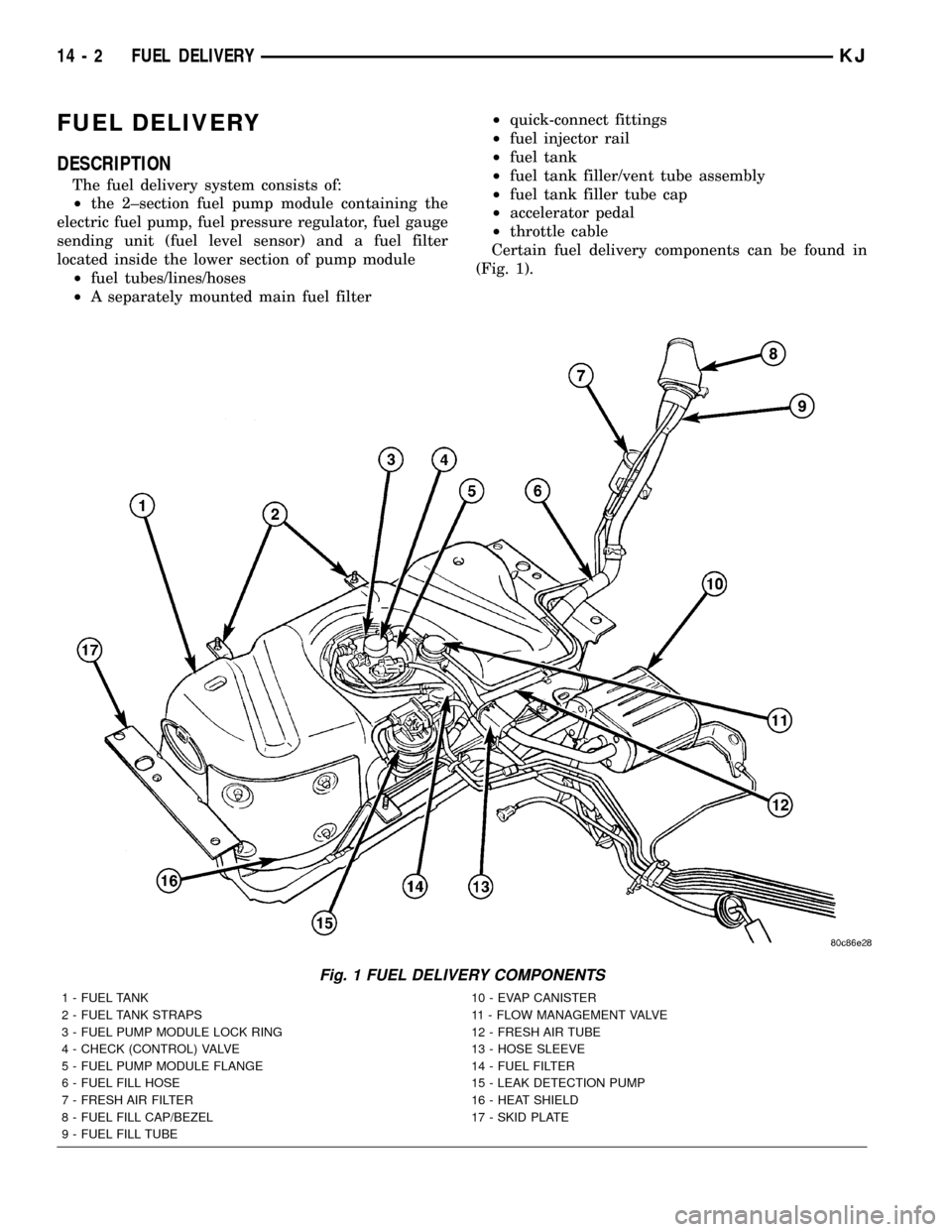
Certain fuel delivery components can be found in
(Fig. 1).
Fig. 1 FUEL DELIVERY COMPONENTS
1 - FUEL TANK 10 - EVAP CANISTER
2 - FUEL TANK STRAPS 11 - FLOW MANAGEMENT VALVE
3 - FUEL PUMP MODULE LOCK RING 12 - FRESH AIR TUBE
4 - CHECK (CONTROL) VALVE 13 - HOSE SLEEVE
5 - FUEL PUMP MODULE FLANGE 14 - FUEL FILTER
6 - FUEL FILL HOSE 15 - LEAK DETECTION PUMP
7 - FRESH AIR FILTER 16 - HEAT SHIELD
8 - FUEL FILL CAP/BEZEL 17 - SKID PLATE
9 - FUEL FILL TUBE
14 - 2 FUEL DELIVERYKJ
Page 1387 of 1803
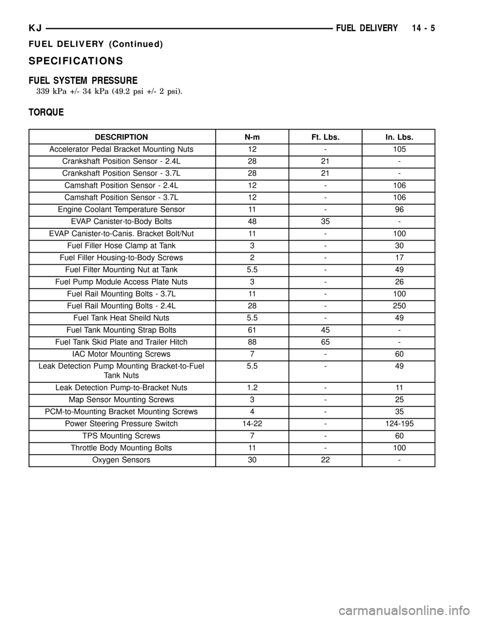
SPECIFICATIONS
FUEL SYSTEM PRESSURE
339 kPa +/- 34 kPa (49.2 psi +/- 2 psi).
TORQUE
DESCRIPTION N-m Ft. Lbs. In. Lbs.
Accelerator Pedal Bracket Mounting Nuts 12 - 105
Crankshaft Position Sensor - 2.4L 28 21 -
Crankshaft Position Sensor - 3.7L 28 21 -
Camshaft Position Sensor - 2.4L 12 - 106
Camshaft Position Sensor - 3.7L 12 - 106
Engine Coolant Temperature Sensor 11 - 96
EVAP Canister-to-Body Bolts 48 35 -
EVAP Canister-to-Canis. Bracket Bolt/Nut 11 - 100
Fuel Filler Hose Clamp at Tank 3 - 30
Fuel Filler Housing-to-Body Screws 2 - 17
Fuel Filter Mounting Nut at Tank 5.5 - 49
Fuel Pump Module Access Plate Nuts 3 - 26
Fuel Rail Mounting Bolts - 3.7L 11 - 100
Fuel Rail Mounting Bolts - 2.4L 28 - 250
Fuel Tank Heat Sheild Nuts 5.5 - 49
Fuel Tank Mounting Strap Bolts 61 45 -
Fuel Tank Skid Plate and Trailer Hitch 88 65 -
IAC Motor Mounting Screws 7 - 60
Leak Detection Pump Mounting Bracket-to-Fuel
Tank Nuts5.5 - 49
Leak Detection Pump-to-Bracket Nuts 1.2 - 11
Map Sensor Mounting Screws 3 - 25
PCM-to-Mounting Bracket Mounting Screws 4 - 35
Power Steering Pressure Switch 14-22 - 124-195
TPS Mounting Screws 7 - 60
Throttle Body Mounting Bolts 11 - 100
Oxygen Sensors 30 22 -
KJFUEL DELIVERY 14 - 5
FUEL DELIVERY (Continued)
Page 1391 of 1803
FUEL LEVEL SENDING UNIT /
SENSOR
DESCRIPTION
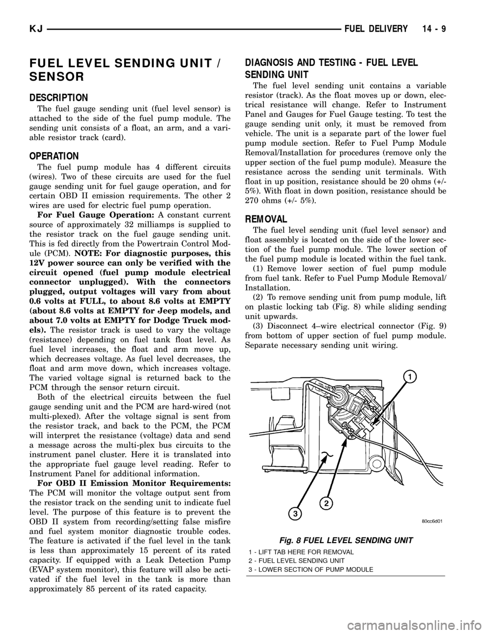
The fuel gauge sending unit (fuel level sensor) is
attached to the side of the fuel pump module. The
sending unit consists of a float, an arm, and a vari-
able resistor track (card).
OPERATION
The fuel pump module has 4 different circuits
(wires). Two of these circuits are used for the fuel
gauge sending unit for fuel gauge operation, and for
certain OBD II emission requirements. The other 2
wires are used for electric fuel pump operation.
For Fuel Gauge Operation:A constant current
source of approximately 32 milliamps is supplied to
the resistor track on the fuel gauge sending unit.
This is fed directly from the Powertrain Control Mod-
ule (PCM).NOTE: For diagnostic purposes, this
12V power source can only be verified with the
circuit opened (fuel pump module electrical
connector unplugged). With the connectors
plugged, output voltages will vary from about
0.6 volts at FULL, to about 8.6 volts at EMPTY
(about 8.6 volts at EMPTY for Jeep models, and
about 7.0 volts at EMPTY for Dodge Truck mod-
els).The resistor track is used to vary the voltage
(resistance) depending on fuel tank float level. As
fuel level increases, the float and arm move up,
which decreases voltage. As fuel level decreases, the
float and arm move down, which increases voltage.
The varied voltage signal is returned back to the
PCM through the sensor return circuit.
Both of the electrical circuits between the fuel
gauge sending unit and the PCM are hard-wired (not
multi-plexed). After the voltage signal is sent from
the resistor track, and back to the PCM, the PCM
will interpret the resistance (voltage) data and send
a message across the multi-plex bus circuits to the
instrument panel cluster. Here it is translated into
the appropriate fuel gauge level reading. Refer to
Instrument Panel for additional information.
For OBD II Emission Monitor Requirements:
The PCM will monitor the voltage output sent from
the resistor track on the sending unit to indicate fuel
level. The purpose of this feature is to prevent the
OBD II system from recording/setting false misfire
and fuel system monitor diagnostic trouble codes.
The feature is activated if the fuel level in the tank
is less than approximately 15 percent of its rated
capacity. If equipped with a Leak Detection Pump
(EVAP system monitor), this feature will also be acti-
vated if the fuel level in the tank is more than
approximately 85 percent of its rated capacity.
DIAGNOSIS AND TESTING - FUEL LEVEL
SENDING UNIT
The fuel level sending unit contains a variable
resistor (track). As the float moves up or down, elec-
trical resistance will change. Refer to Instrument
Panel and Gauges for Fuel Gauge testing. To test the
gauge sending unit only, it must be removed from
vehicle. The unit is a separate part of the lower fuel
pump module section. Refer to Fuel Pump Module
Removal/Installation for procedures (remove only the
upper section of the fuel pump module). Measure the
resistance across the sending unit terminals. With
float in up position, resistance should be 20 ohms (+/-
5%). With float in down position, resistance should be
270 ohms (+/- 5%).
REMOVAL
The fuel level sending unit (fuel level sensor) and
float assembly is located on the side of the lower sec-
tion of the fuel pump module. The lower section of
the fuel pump module is located within the fuel tank.
(1) Remove lower section of fuel pump module
from fuel tank. Refer to Fuel Pump Module Removal/
Installation.
(2) To remove sending unit from pump module, lift
on plastic locking tab (Fig. 8) while sliding sending
unit upwards.
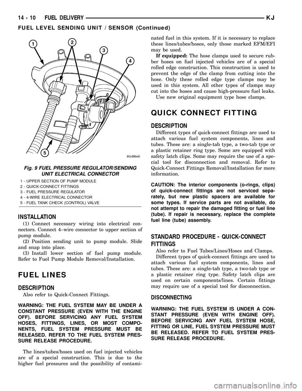
(3) Disconnect 4±wire electrical connector (Fig. 9)
from bottom of upper section of fuel pump module.
Separate necessary sending unit wiring.
Fig. 8 FUEL LEVEL SENDING UNIT
1 - LIFT TAB HERE FOR REMOVAL
2 - FUEL LEVEL SENDING UNIT
3 - LOWER SECTION OF PUMP MODULE
KJFUEL DELIVERY 14 - 9
Page 1392 of 1803
INSTALLATION
(1) Connect necessary wiring into electrical con-
nectors. Connect 4±wire connector to upper section of
pump module.
(2) Position sending unit to pump module. Slide
and snap into place.
(3) Install lower section of fuel pump module.
Refer to Fuel Pump Module Removal/Installation.
FUEL LINES
DESCRIPTION
Also refer to Quick-Connect Fittings.
WARNING: THE FUEL SYSTEM MAY BE UNDER A
CONSTANT PRESSURE (EVEN WITH THE ENGINE
OFF). BEFORE SERVICING ANY FUEL SYSTEM
HOSES, FITTINGS, LINES, OR MOST COMPO-
NENTS, FUEL SYSTEM PRESSURE MUST BE
RELEASED. REFER TO THE FUEL SYSTEM PRES-
SURE RELEASE PROCEDURE.
The lines/tubes/hoses used on fuel injected vehicles
are of a special construction. This is due to the
higher fuel pressures and the possibility of contami-nated fuel in this system. If it is necessary to replace
these lines/tubes/hoses, only those marked EFM/EFI
may be used.
If equipped:The hose clamps used to secure rub-
ber hoses on fuel injected vehicles are of a special
rolled edge construction. This construction is used to
prevent the edge of the clamp from cutting into the
hose. Only these rolled edge type clamps may be
used in this system. All other types of clamps may
cut into the hoses and cause high-pressure fuel leaks.
Use new original equipment type hose clamps.
QUICK CONNECT FITTING
DESCRIPTION
Different types of quick-connect fittings are used to
attach various fuel system components, lines and
tubes. These are: a single-tab type, a two-tab type or
a plastic retainer ring type. Some are equipped with
safety latch clips. Some may require the use of a spe-
cial tool for disconnection and removal. Refer to
Quick-Connect Fittings Removal/Installation for more
information.
CAUTION: The interior components (o-rings, clips)
of quick-connect fittings are not serviced sepa-
rately, but new plastic spacers are available for
some types. If service parts are not available, do
not attempt to repair the damaged fitting or fuel line
(tube). If repair is necessary, replace the complete
fuel line (tube) assembly.
STANDARD PROCEDURE - QUICK-CONNECT
FITTINGS
Also refer to Fuel Tubes/Lines/Hoses and Clamps.
Different types of quick-connect fittings are used to
attach various fuel system components, lines and
tubes. These are: a single-tab type, a two-tab type or
a plastic retainer ring type. Safety latch clips are
used on certain components/lines. Certain fittings
may require use of a special tool for disconnection.
DISCONNECTING
WARNING: THE FUEL SYSTEM IS UNDER A CON-
STANT PRESSURE (EVEN WITH ENGINE OFF).
BEFORE SERVICING ANY FUEL SYSTEM HOSE,
FITTING OR LINE, FUEL SYSTEM PRESSURE MUST
BE RELEASED. REFER TO FUEL SYSTEM PRES-
SURE RELEASE PROCEDURE.
Fig. 9 FUEL PRESSURE REGULATOR/SENDING
UNIT ELECTRICAL CONNECTOR
1 - UPPER SECTION OF PUMP MODULE
2 - QUICK-CONNECT FITTINGS
3 - FUEL PRESSURE REGULATOR
4 - 4-WIRE ELECTRICAL CONNECTOR
5 - FUEL TANK CHECK (CONTROL) VALVE
14 - 10 FUEL DELIVERYKJ
FUEL LEVEL SENDING UNIT / SENSOR (Continued)
Page 1400 of 1803
(17) When LCS adapter test leads are attached
into relay cavities, fuel pumpwill be activated.
Determine fuel pump amperage on DRB screen.
Amperage should be below 10.0 amps. If amperage is
below 10.0 amps, and specifications for the Fuel
Pump Pressure, Fuel Pump Capacity and Fuel Pres-
sure Leak Down tests were met, the fuel pump mod-
ule is OK.
(18) If amperage is more than 10.0 amps, replace
fuel pump module assembly. The electric fuel pump
is not serviced separately.
(19) Disconnect test leads from relay cavities
immediately after testing.
FUEL PUMP MODULE
DESCRIPTION
The fuel pump module assembly is located in the
fuel tank (Fig. 1). The assembly is divided into 2±sec-
tions, upper and lower. The lower section is locked to
the bottom of the fuel tank. The complete assembly
contains the following components:
²A fuel pressure regulator
²A separate fuel pick-up, or inlet filter
²An electric fuel pump
²A lockring to retain upper section of pump mod-
ule to tank
²A rollover valve
²A vent fitting for ORVR system
²A soft gasket between tank flange and module
²A fuel gauge sending unit (fuel level sensor)
²Two fuel line connections (supply and return)
The fuel gauge sending unit may be serviced sepa-
rately. If the electrical fuel pump, primary inlet filter
or fuel pressure regulator require service, the lower
section of the fuel pump module must be replaced.
OPERATION
Refer to Fuel Pump, Inlet Filter, Fuel Pressure
Regulator and Fuel Gauge Sending Unit.
REMOVAL
The fuel pump module is divided into 2 sections,
upper and lower. To service the check (control) valve,
replace only the upper section. To service the fuel
gauge sending unit, remove the upper section. To ser-
vice the electric fuel pump, fuel pressure regulator or
primary inlet filter, remove both sections and replace
lower section.
Fuel tank removal will not be necessary for
fuel pump module removal. Access is from rear
cargo area.
(1) Four cargo holdown clamps are located inside
the vehicle on the floor of the rear cargo area.Remove the 2 rearward mounted clamps by drilling
out the clamp rivets.
(2) Fold carpeting forward to gain access to fuel
pump module access plate (Fig. 25).
(3) Remove 4 fuel pump module access plate nuts
(Fig. 25).
(4) While applying heat from a heat gun, carefully
pry up fuel pump module access plate. Take care not
to bend plate.
(5) Thoroughly clean area around top of pump
module to prevent contaminants from entering fuel
tank or fuel lines.
WARNING: THE FUEL SYSTEM IS UNDER A CON-
STANT PRESSURE EVEN WITH ENGINE OFF.
BEFORE SERVICING THE FUEL PUMP MODULE,
FUEL SYSTEM PRESSURE MUST BE RELEASED.
(6) Release fuel system pressure. Refer to Fuel
System Pressure Release procedure.
(7) Disconnect 2 fuel lines at fuel pump module
(Fig. 26) by pressing on 2 buttons at sides of fitting.
(8) Disconnect electrical connector (Fig. 26) at top
of fuel pump module by sliding red colored tab first
to unlock, and push grey colored tab down for
removal.
(9) Disconnect ORVR hose clamp and hose (Fig.
26) at pump module fitting.
(10) Remove module lockring (Fig. 26) using a
brass drift and hammer (counter-clockwise).
(11) Carefully lift upper section of pump module
(Fig. 26) from fuel tank exposing connections(lift
upper section from tank very slowly until rub-
ber gasket can be retained. If not, gasket will
fall into fuel tank.)
(a) Disconnect electrical connector (Fig. 27) at
bottom of upper pump module section.
(b) Disconnect fuel pressure regulator (Fig. 27)
at bottom of upper pump module section. Press on
2 locking tabs.
(c) Disconnect fuel return line (Fig. 27) at bot-
tom of upper pump module section. Press on 2
locking tabs.
(d) Remove upper section of pump module (Fig.
28) from fuel tank.
(12) Using an approved gas holding tank, drain
fuel tank through pump module opening.If check
(control) valve, or, only upper section of pump
module is being serviced, tank draining is not
necessary. If any other fuel pump module com-
ponent is being serviced, the tank must be com-
pletely drained to the bottom.
(13) To remove lower section of pump module from
fuel tank:
(a) Using finger pressure, push on plastic
release tab (Fig. 29) while sliding lock tab upward.
14 - 18 FUEL DELIVERYKJ
FUEL PUMP (Continued)