2002 JEEP LIBERTY seats
[x] Cancel search: seatsPage 653 of 1803

(4) Remove the screw that secures the front seat
belt buckle anchor to the bracket near the rear of the
inboard seat track (Fig. 22).
(5) Remove the two screws that secure the inboard
seat cushion side shield to the seat cushion frame.
(6) Remove the two screws that secure the inboard
seat track to the rear inboard corner of the seat cush-
ion frame.
(7) Disconnect the seat belt switch pigtail wire
routing clip from the locating hole in the seat cushion
frame.
(8) Remove the seat belt switch pigtail wire from
between the seat cushion frame and the seat track by
gently prying the inboard seat track away from the
inboard rear corner of the seat cushion frame far
enough to slide the pigtail wire from between them.
(9) Remove the front seat belt buckle from the
inboard seat cushion side shield.
INSTALLATION
WARNING: ON VEHICLES EQUIPPED WITH AIRBAGS,
DISABLE THE SUPPLEMENTAL RESTRAINT SYSTEM
BEFORE ATTEMPTING ANY STEERING WHEEL,
STEERING COLUMN, DRIVER AIRBAG, PASSENGER
AIRBAG, SEAT BELT TENSIONER, FRONT IMPACT
SENSORS, SIDE CURTAIN AIRBAG, OR INSTRUMENT
PANEL COMPONENT DIAGNOSIS OR SERVICE. DIS-
CONNECT AND ISOLATE THE BATTERY NEGATIVE
(GROUND) CABLE, THEN WAIT TWO MINUTES FOR
THE SYSTEM CAPACITOR TO DISCHARGE BEFORE
PERFORMING FURTHER DIAGNOSIS OR SERVICE.
THIS IS THE ONLY SURE WAY TO DISABLE THE SUP-
PLEMENTAL RESTRAINT SYSTEM. FAILURE TO TAKE
THE PROPER PRECAUTIONS COULD RESULT INACCIDENTAL AIRBAG DEPLOYMENT AND POSSIBLE
PERSONAL INJURY.
WARNING: DURING AND FOLLOWING ANY SEAT
BELT SERVICE, CAREFULLY INSPECT ALL SEAT
BELTS, BUCKLES, MOUNTING HARDWARE, AND
RETRACTORS FOR PROPER INSTALLATION,
OPERATION, OR DAMAGE. REPLACE ANY BELT
THAT IS CUT, FRAYED, OR TORN. STRAIGHTEN
ANY BELT THAT IS TWISTED. TIGHTEN ANY
LOOSE FASTENERS. REPLACE ANY BELT THAT
HAS A DAMAGED OR INOPERATIVE BUCKLE OR
RETRACTOR. REPLACE ANY BELT THAT HAS A
BENT OR DAMAGED LATCH PLATE OR ANCHOR
PLATE. NEVER ATTEMPT TO REPAIR A SEAT BELT
COMPONENT. ALWAYS REPLACE DAMAGED OR
FAULTY SEAT BELT COMPONENTS WITH THE COR-
RECT, NEW AND UNUSED REPLACEMENT PARTS
LISTED IN THE MOPAR PARTS CATALOG.
(1) Position the front seat belt buckle to the
inboard seat cushion side shield (Fig. 22).
(2)
Position the seat belt switch pigtail wire between
the seat cushion frame and the seat track by gently pry-
ing the inboard seat track away from the inboard rear
corner of the seat cushion frame far enough to slide the
pigtail wire into position between them.
(3) Engage the seat belt switch pigtail wire routing
clip into the locating hole in the seat cushion frame.
(4) Install and tighten the two screws that secure
the inboard seat track to the rear inboard corner of
the seat cushion frame. Tighten the screws to 28 N´m
(21 ft. lbs.).
(5) Position the inboard seat cushion side shield to
the seat cushion frame.
(6) Install and tighten the two screws that secure
the inboard seat cushion side shield to the seat cush-
ion frame. Tighten the screws to 1 N´m (9 in. lbs.).
(7) Position the front seat belt buckle anchor to
the bracket on the inboard side of the seat track.
(8) Install and tighten the screw that secures the
front seat belt buckle anchor to the bracket on the
inboard side of the seat track. Tighten the screw to
43 N´m (32 ft. lbs.).
(9)
Reconnect the seat belt switch pigtail wire connec-
tor to the seat wire harness connector on the seat cush-
ion frame bracket located under the rear edge of the seat
cushion near the inboard side of the seat (Fig. 21).
(10) Reinstall the front seat and seat track to the
floor panel as a unit. (Refer to 23 - BODY/SEATS/
SEAT - FRONT - INSTALLATION).
(11) Do not reconnect the battery negative cable at
this time. The airbag system verification test proce-
dure should be performed following service of any
supplemental restraint system component. (Refer to
8 - ELECTRICAL/RESTRAINTS - STANDARD PRO-
CEDURE - VERIFICATION TEST).
Fig. 22 Front Seat Belt Buckle Remove/Install
1 - FRONT SEAT BELT BUCKLE
2 - INBOARD SIDE SHIELD
3 - SCREW
4 - PIGTAIL WIRE
8O - 26 RESTRAINTSKJ
FRONT SEAT BELT BUCKLE (Continued)
Page 659 of 1803

REAR CENTER SEAT BELT &
RETRACTOR
REMOVAL
WARNING: DURING AND FOLLOWING ANY SEAT
BELT SERVICE, CAREFULLY INSPECT ALL SEAT
BELTS, BUCKLES, MOUNTING HARDWARE, AND
RETRACTORS FOR PROPER INSTALLATION,
OPERATION, OR DAMAGE. REPLACE ANY BELT
THAT IS CUT, FRAYED, OR TORN. STRAIGHTEN
ANY BELT THAT IS TWISTED. TIGHTEN ANY
LOOSE FASTENERS. REPLACE ANY BELT THAT
HAS A DAMAGED OR INOPERATIVE BUCKLE OR
RETRACTOR. REPLACE ANY BELT THAT HAS A
BENT OR DAMAGED LATCH PLATE OR ANCHOR
PLATE. NEVER ATTEMPT TO REPAIR A SEAT BELT
COMPONENT. ALWAYS REPLACE DAMAGED OR
FAULTY SEAT BELT COMPONENTS WITH THE COR-
RECT, NEW AND UNUSED REPLACEMENT PARTS
LISTED IN THE MOPAR PARTS CATALOG.
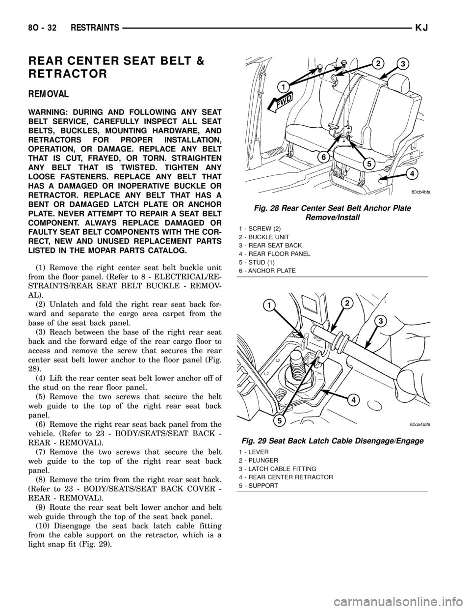
(1) Remove the right center seat belt buckle unit
from the floor panel. (Refer to 8 - ELECTRICAL/RE-
STRAINTS/REAR SEAT BELT BUCKLE - REMOV-
AL).
(2) Unlatch and fold the right rear seat back for-
ward and separate the cargo area carpet from the
base of the seat back panel.
(3) Reach between the base of the right rear seat
back and the forward edge of the rear cargo floor to
access and remove the screw that secures the rear
center seat belt lower anchor to the floor panel (Fig.
28).
(4) Lift the rear center seat belt lower anchor off of
the stud on the rear floor panel.
(5) Remove the two screws that secure the belt
web guide to the top of the right rear seat back
panel.
(6) Remove the right rear seat back panel from the
vehicle. (Refer to 23 - BODY/SEATS/SEAT BACK -
REAR - REMOVAL).
(7) Remove the two screws that secure the belt
web guide to the top of the right rear seat back
panel.
(8) Remove the trim from the right rear seat back.
(Refer to 23 - BODY/SEATS/SEAT BACK COVER -
REAR - REMOVAL).
(9) Route the rear seat belt lower anchor and belt
web guide through the top of the seat back panel.
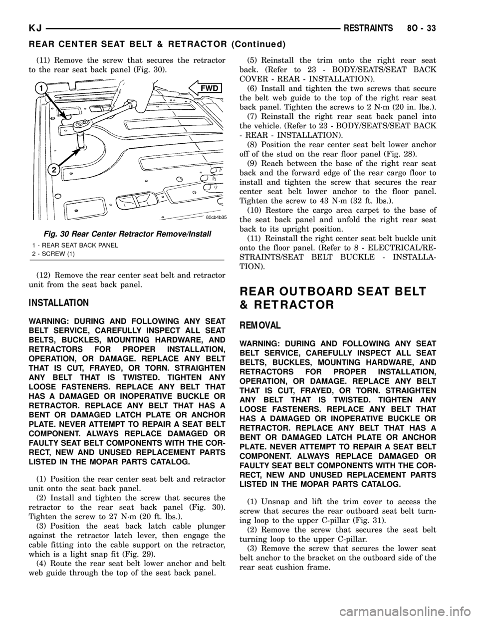
(10) Disengage the seat back latch cable fitting
from the cable support on the retractor, which is a
light snap fit (Fig. 29).
Fig. 28 Rear Center Seat Belt Anchor Plate
Remove/Install
1 - SCREW (2)
2 - BUCKLE UNIT
3 - REAR SEAT BACK
4 - REAR FLOOR PANEL
5 - STUD (1)
6 - ANCHOR PLATE
Fig. 29 Seat Back Latch Cable Disengage/Engage
1 - LEVER
2 - PLUNGER
3 - LATCH CABLE FITTING
4 - REAR CENTER RETRACTOR
5 - SUPPORT
8O - 32 RESTRAINTSKJ
Page 660 of 1803

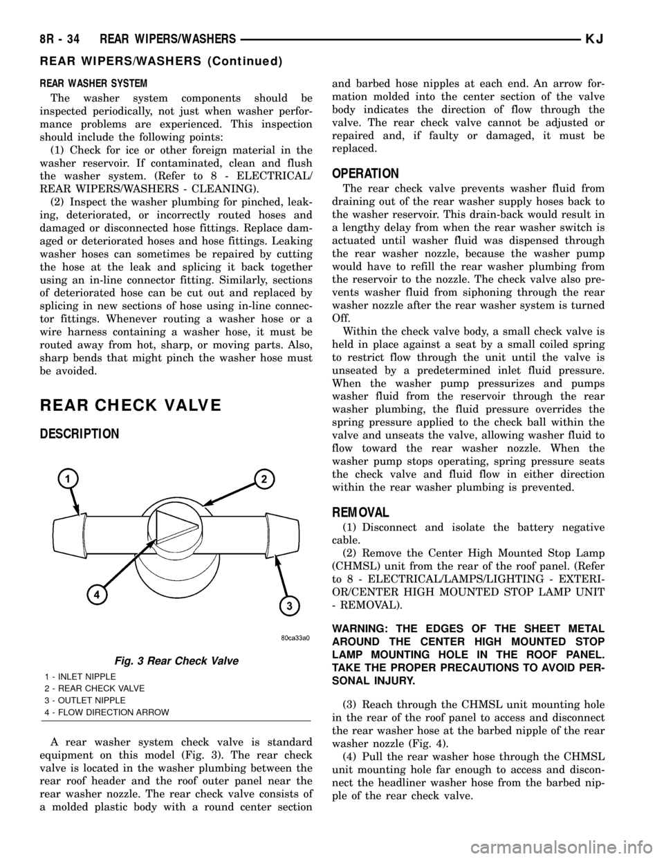
(11) Remove the screw that secures the retractor
to the rear seat back panel (Fig. 30).
(12) Remove the rear center seat belt and retractor
unit from the seat back panel.
INSTALLATION
WARNING: DURING AND FOLLOWING ANY SEAT
BELT SERVICE, CAREFULLY INSPECT ALL SEAT
BELTS, BUCKLES, MOUNTING HARDWARE, AND
RETRACTORS FOR PROPER INSTALLATION,
OPERATION, OR DAMAGE. REPLACE ANY BELT
THAT IS CUT, FRAYED, OR TORN. STRAIGHTEN
ANY BELT THAT IS TWISTED. TIGHTEN ANY
LOOSE FASTENERS. REPLACE ANY BELT THAT
HAS A DAMAGED OR INOPERATIVE BUCKLE OR
RETRACTOR. REPLACE ANY BELT THAT HAS A
BENT OR DAMAGED LATCH PLATE OR ANCHOR
PLATE. NEVER ATTEMPT TO REPAIR A SEAT BELT
COMPONENT. ALWAYS REPLACE DAMAGED OR
FAULTY SEAT BELT COMPONENTS WITH THE COR-
RECT, NEW AND UNUSED REPLACEMENT PARTS
LISTED IN THE MOPAR PARTS CATALOG.
(1) Position the rear center seat belt and retractor
unit onto the seat back panel.
(2) Install and tighten the screw that secures the
retractor to the rear seat back panel (Fig. 30).
Tighten the screw to 27 N´m (20 ft. lbs.).
(3) Position the seat back latch cable plunger
against the retractor latch lever, then engage the
cable fitting into the cable support on the retractor,
which is a light snap fit (Fig. 29).
(4) Route the rear seat belt lower anchor and belt
web guide through the top of the seat back panel.(5) Reinstall the trim onto the right rear seat
back. (Refer to 23 - BODY/SEATS/SEAT BACK
COVER - REAR - INSTALLATION).
(6) Install and tighten the two screws that secure
the belt web guide to the top of the right rear seat
back panel. Tighten the screws to 2 N´m (20 in. lbs.).
(7) Reinstall the right rear seat back panel into
the vehicle. (Refer to 23 - BODY/SEATS/SEAT BACK
- REAR - INSTALLATION).
(8) Position the rear center seat belt lower anchor
off of the stud on the rear floor panel (Fig. 28).
(9) Reach between the base of the right rear seat
back and the forward edge of the rear cargo floor to
install and tighten the screw that secures the rear
center seat belt lower anchor to the floor panel.
Tighten the screw to 43 N´m (32 ft. lbs.).
(10) Restore the cargo area carpet to the base of
the seat back panel and unfold the right rear seat
back to its upright position.
(11) Reinstall the right center seat belt buckle unit
onto the floor panel. (Refer to 8 - ELECTRICAL/RE-
STRAINTS/SEAT BELT BUCKLE - INSTALLA-
TION).
REAR OUTBOARD SEAT BELT
& RETRACTOR
REMOVAL
WARNING: DURING AND FOLLOWING ANY SEAT
BELT SERVICE, CAREFULLY INSPECT ALL SEAT
BELTS, BUCKLES, MOUNTING HARDWARE, AND
RETRACTORS FOR PROPER INSTALLATION,
OPERATION, OR DAMAGE. REPLACE ANY BELT
THAT IS CUT, FRAYED, OR TORN. STRAIGHTEN
ANY BELT THAT IS TWISTED. TIGHTEN ANY
LOOSE FASTENERS. REPLACE ANY BELT THAT
HAS A DAMAGED OR INOPERATIVE BUCKLE OR
RETRACTOR. REPLACE ANY BELT THAT HAS A
BENT OR DAMAGED LATCH PLATE OR ANCHOR
PLATE. NEVER ATTEMPT TO REPAIR A SEAT BELT
COMPONENT. ALWAYS REPLACE DAMAGED OR
FAULTY SEAT BELT COMPONENTS WITH THE COR-
RECT, NEW AND UNUSED REPLACEMENT PARTS
LISTED IN THE MOPAR PARTS CATALOG.
(1) Unsnap and lift the trim cover to access the
screw that secures the rear outboard seat belt turn-
ing loop to the upper C-pillar (Fig. 31).
(2) Remove the screw that secures the seat belt
turning loop to the upper C-pillar.
(3) Remove the screw that secures the lower seat
belt anchor to the bracket on the outboard side of the
rear seat cushion frame.
Fig. 30 Rear Center Retractor Remove/Install
1 - REAR SEAT BACK PANEL
2 - SCREW (1)
KJRESTRAINTS 8O - 33
REAR CENTER SEAT BELT & RETRACTOR (Continued)
Page 710 of 1803

OPERATION
The front check valve provides more than one func-
tion in this application. It serves as a wye connector
fitting between the cowl grille panel and washer noz-
zle sections of the front washer supply hose. It also
prevents washer fluid from draining out of the front
washer supply hoses back to the washer reservoir.
This drain-back would result in a lengthy delay when
the front washer switch is actuated until washer
fluid was dispensed through the front washer noz-
zles, because the washer pump would have to refill
the front washer plumbing from the reservoir to the
nozzles. Finally, the front check valve prevents
washer fluid from siphoning through the front
washer nozzles after the front washer system is
turned Off.
Within the check valve body, a small check valve is
held in place against a seat by a small coiled spring
to restrict flow through the unit until the valve is
unseated by a predetermined inlet fluid pressure.
When the washer pump pressurizes and pumps
washer fluid from the reservoir through the front
washer plumbing, the fluid pressure overrides the
spring pressure applied to the check valve and
unseats the valve, allowing washer fluid to flow
toward the front washer nozzles. When the washer
pump stops operating, spring pressure seats the
check valve and fluid flow in either direction within
the front washer plumbing is prevented.
REMOVAL
(1) Unlatch and open the hood.
(2) Remove both front wiper arms from the wiper
pivots. (Refer to 8 - ELECTRICAL/WIPERS/WASH-
ERS - FRONT/FRONT WIPER ARM - REMOVAL).
(3) Remove the cowl plenum cover/grille panel
from over the cowl plenum. (Refer to 23 - BODY/EX-
TERIOR/COWL GRILLE - REMOVAL).
(4) From the underside of the cowl plenum cover/
grille panel, disconnect the cowl plenum and washer
nozzle hoses from the three barbed nipples of the
front check valve (Fig. 4).
(5) Remove the front check valve from the under-
side of the cowl plenum cover/grille panel.
INSTALLATION
(1) Position the front check valve to the underside
of the cowl plenum cover/grille panel (Fig. 4). Be cer-
tain that the flow direction arrow molded into the
front check valve body is oriented towards the front
washer nozzles.
(2) From the underside of the cowl plenum cover/
grille panel, reconnect the cowl plenum and washer
nozzle hoses to the three barbed nipples of the front
check valve.
(3) Reinstall the cowl plenum cover/grille panel
over the cowl plenum. (Refer to 23 - BODY/EXTERI-
OR/COWL GRILLE - INSTALLATION).
(4) Reinstall both front wiper arms onto the wiper
pivots. (Refer to 8 - ELECTRICAL/FRONT WIPERS/
WASHERS/FRONT WIPER ARM - INSTALLATION).
(5) Close and latch the hood.
Fig. 3 Front Check Valve
1 - INLET NIPPLE
2 - FRONT CHECK VALVE
3 - OUTLET NIPPLE (2)
4 - FLOW DIRECTION ARROW
Fig. 4 Front Check Valve Remove/Install
1 - WASHER NOZZLE HOSE (RIGHT)
2 - FRONT CHECK VALVE
3 - COWL PLENUM WASHER HOSE
4 - ROUTING CLIP
5 - COWL GRILLE COVER (UNDERSIDE)
6 - WASHER NOZZLE HOSE (LEFT)
KJFRONT WIPERS/WASHERS 8R - 9
FRONT CHECK VALVE (Continued)
Page 735 of 1803

REAR WASHER SYSTEM
The washer system components should be
inspected periodically, not just when washer perfor-
mance problems are experienced. This inspection
should include the following points:
(1) Check for ice or other foreign material in the
washer reservoir. If contaminated, clean and flush
the washer system. (Refer to 8 - ELECTRICAL/
REAR WIPERS/WASHERS - CLEANING).
(2) Inspect the washer plumbing for pinched, leak-
ing, deteriorated, or incorrectly routed hoses and
damaged or disconnected hose fittings. Replace dam-
aged or deteriorated hoses and hose fittings. Leaking
washer hoses can sometimes be repaired by cutting
the hose at the leak and splicing it back together
using an in-line connector fitting. Similarly, sections
of deteriorated hose can be cut out and replaced by
splicing in new sections of hose using in-line connec-
tor fittings. Whenever routing a washer hose or a
wire harness containing a washer hose, it must be
routed away from hot, sharp, or moving parts. Also,
sharp bends that might pinch the washer hose must
be avoided.
REAR CHECK VALVE
DESCRIPTION
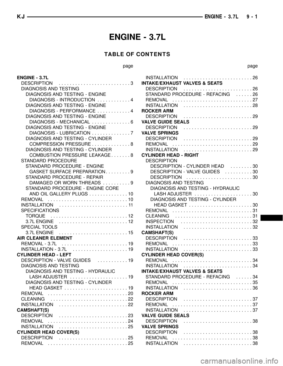
A rear washer system check valve is standard
equipment on this model (Fig. 3). The rear check
valve is located in the washer plumbing between the
rear roof header and the roof outer panel near the
rear washer nozzle. The rear check valve consists of
a molded plastic body with a round center sectionand barbed hose nipples at each end. An arrow for-
mation molded into the center section of the valve
body indicates the direction of flow through the
valve. The rear check valve cannot be adjusted or
repaired and, if faulty or damaged, it must be
replaced.
OPERATION
The rear check valve prevents washer fluid from
draining out of the rear washer supply hoses back to
the washer reservoir. This drain-back would result in
a lengthy delay from when the rear washer switch is
actuated until washer fluid was dispensed through
the rear washer nozzle, because the washer pump
would have to refill the rear washer plumbing from
the reservoir to the nozzle. The check valve also pre-
vents washer fluid from siphoning through the rear
washer nozzle after the rear washer system is turned
Off.
Within the check valve body, a small check valve is
held in place against a seat by a small coiled spring
to restrict flow through the unit until the valve is
unseated by a predetermined inlet fluid pressure.
When the washer pump pressurizes and pumps
washer fluid from the reservoir through the rear
washer plumbing, the fluid pressure overrides the
spring pressure applied to the check ball within the
valve and unseats the valve, allowing washer fluid to
flow toward the rear washer nozzle. When the
washer pump stops operating, spring pressure seats
the check valve and fluid flow in either direction
within the rear washer plumbing is prevented.
REMOVAL
(1) Disconnect and isolate the battery negative
cable.
(2) Remove the Center High Mounted Stop Lamp
(CHMSL) unit from the rear of the roof panel. (Refer
to 8 - ELECTRICAL/LAMPS/LIGHTING - EXTERI-
OR/CENTER HIGH MOUNTED STOP LAMP UNIT
- REMOVAL).
WARNING: THE EDGES OF THE SHEET METAL
AROUND THE CENTER HIGH MOUNTED STOP
LAMP MOUNTING HOLE IN THE ROOF PANEL.
TAKE THE PROPER PRECAUTIONS TO AVOID PER-
SONAL INJURY.
(3) Reach through the CHMSL unit mounting hole
in the rear of the roof panel to access and disconnect
the rear washer hose at the barbed nipple of the rear
washer nozzle (Fig. 4).
(4) Pull the rear washer hose through the CHMSL
unit mounting hole far enough to access and discon-
nect the headliner washer hose from the barbed nip-
ple of the rear check valve.
Fig. 3 Rear Check Valve
1 - INLET NIPPLE
2 - REAR CHECK VALVE
3 - OUTLET NIPPLE
4 - FLOW DIRECTION ARROW
8R - 34 REAR WIPERS/WASHERSKJ
REAR WIPERS/WASHERS (Continued)
Page 762 of 1803

8W-02 COMPONENT INDEX
Component Page
A/C Compressor Clutch Relay........... 8Wa-42
A/C Compressor Clutch................ 8Wa-42
A/C-Heater Control................... 8Wa-42
A/C High Pressure Switch.............. 8Wa-42
A/C Low Pressure Switch............... 8Wa-42
A/C Pressure Transducer............... 8Wa-42
Accelerator Pedal Position Sensor........ 8Wa-30
Airbag Control Module................. 8Wa-43
Ambient Temperature Sensor............ 8Wa-45
Antenna Module...................... 8Wa-47
Antenna............................ 8Wa-47
Ash Receiver Lamp................... 8Wa-44
Auto Shut Down Relay................. 8Wa-30
Back-Up Lamp Switch................. 8Wa-31
Battery Temperature Sensor......... 8Wa-20, 30
Battery............................. 8Wa-20
Blend Door Actuator................... 8Wa-42
Blower Motor Relay................... 8Wa-42
Blower Motor Resistor Block............ 8Wa-42
Blower Motor........................ 8Wa-42
Body Control Module.................. 8Wa-45
Boost Pressure Sensor................. 8Wa-30
Brake Lamp Switch................... 8Wa-33
Brake Pressure Switch................. 8Wa-35
Cabin Heater Relay................... 8Wa-42
Cabin Heater........................ 8Wa-42
Camshaft Position Sensor.............. 8Wa-30
Capacitor........................... 8Wa-30
Cargo Lamp......................... 8Wa-44
CD Changer......................... 8Wa-47
Center High Mounted Stop Lamp........ 8Wa-51
Cigar Lighter........................ 8Wa-41
Circuit Breakers...................... 8Wa-12
Clockspring................. 8Wa-33, 41, 43, 47
Clutch Interlock Switch................ 8Wa-21
Clutch Switch Override Relay........... 8Wa-21
Coil On Plugs........................ 8Wa-30
Coil Rail............................ 8Wa-30
Compass Mini-Trip Computer........... 8Wa-49
Controller Antilock Brake.............. 8Wa-35
Courtesy Lamps...................... 8Wa-44
Crankshaft Position Sensor............. 8Wa-30
Curtain Airbags...................... 8Wa-43
Cylinder Lock Switches................ 8Wa-61
Data Link Connector.................. 8Wa-18
Daytime Running Lamp Relay........... 8Wa-50
Defogger Relay....................... 8Wa-48
Diagnostic Junction Port............... 8Wa-18
Dome Lamp......................... 8Wa-44
Door Ajar Switches.................... 8Wa-45
Door Lock Motor/Ajar Switches.......... 8Wa-61
Door Lock Relay...................... 8Wa-61Component Page
Door Lock Switches................... 8Wa-61
Door Speakers....................... 8Wa-47
Driver Airbag Squib 1................. 8Wa-43
Driver Airbag Squib 2................. 8Wa-43
Driver Door Unlock Relay.............. 8Wa-61
Driver Seat Belt Switch................ 8Wa-40
Driver Seat Belt Tensioner.............. 8Wa-43
EGR Solenoid........................ 8Wa-30
Electric Brake Provision................ 8Wa-54
Engine Control Module................ 8Wa-30
Engine Coolant Level Sensor............ 8Wa-40
Engine Coolant Temperature Sensor...... 8Wa-30
Engine Oil Pressure Sensor............. 8Wa-30
EVAP/Purge Solenoid.................. 8Wa-30
Flip-Up Glass Release Motor............ 8Wa-61
Flip-Up Glass Release Switch........... 8Wa-61
Fog Lamps.......................... 8Wa-50
Front Fog Lamp Relay................. 8Wa-50
Front Wiper Motor.................... 8Wa-53
Fuel Heater Relay.................... 8Wa-30
Fuel Heater......................... 8Wa-30
Fuel Injectors........................ 8Wa-30
Fuel Pressure Sensor.................. 8Wa-30
Fuel Pressure Solenoid................. 8Wa-30
Fuel Pump Module.................... 8Wa-30
Fuel Pump Relay..................... 8Wa-30
Fuses........................... 8Wa-10, 12
Fusible Link......................... 8Wa-20
Grounds............................ 8Wa-15
Generator........................... 8Wa-20
Glow Plugs.......................... 8Wa-30
Hazard Switch/Combination Flasher...... 8Wa-52
Headlamp Leveling Switch.............. 8Wa-50
Headlamps.......................... 8Wa-50
Heated Seats........................ 8Wa-63
High Beam Relay..................... 8Wa-50
Horns.............................. 8Wa-41
Hood Ajar Switch..................... 8Wa-45
Idle Air Control Motor................. 8Wa-30
Ignition Switch....................... 8Wa-10
Impact Sensors....................... 8Wa-43
Input Speed Sensor................... 8Wa-31
Instrument Cluster................... 8Wa-40
Instrument Panel Speakers............. 8Wa-47
Intake Air Temperature Sensor.......... 8Wa-30
Intrusion Sensor..................... 8Wa-49
Junction Block....................... 8Wa-12
Knock Sensor........................ 8Wa-30
Leak Detection Pump.................. 8Wa-30
Leveling Motors...................... 8Wa-50
License Lamp........................ 8Wa-51
Line Pressure Sensor.................. 8Wa-31
KJ8W-02 COMPONENT INDEX8Wa-02-1
Page 763 of 1803

Component Page
Low Beam Relay..................... 8Wa-50
Manifold Absolute Pressure Sensor....... 8Wa-30
Multi-Function Switch........... 8Wa-50, 52, 53
Output Speed Sensor.................. 8Wa-31
Overhead Map/Reading Lamp........... 8Wa-44
Oxygen Sensors...................... 8Wa-30
Oxygen Sensor Downstream Relay........ 8Wa-30
Park Brake Switch.................... 8Wa-40
Park Lamp Relay..................... 8Wa-50
Park/Turn Signal Lamps............ 8Wa-50, 52
Passenger Airbag..................... 8Wa-43
Passenger Door Unlock Relay........... 8Wa-61
Passenger Seat Belt Switch............. 8Wa-40
Position Lamps...................... 8Wa-50
Power Distribution Center.............. 8Wa-10
Power Mirrors....................... 8Wa-62
Power Outlet........................ 8Wa-41
Power Seats......................... 8Wa-63
Power Steering Pressure Switch......... 8Wa-30
Power Windows...................... 8Wa-60
Powertrain Control Module............. 8Wa-30
Radiator Fans....................... 8Wa-30
Radio Choke......................... 8Wa-47
Radio.............................. 8Wa-47
Rear Fog Lamp Relay................. 8Wa-51
Rear Power Outlet.................... 8Wa-41
Rear Power Window Switch............. 8Wa-60
Rear Wheel Speed Sensor.............. 8Wa-35
Rear Window Defogger................. 8Wa-48
Rear Wiper Motor.................... 8Wa-53
Red Brake Warning Indicator Switch...... 8Wa-40Component Page
Remote Keyless Entry Module........... 8Wa-45
Remote Radio Switches................ 8Wa-47
Splices............................. 8Wa-10
Sentry Key Immobilizer Module.......... 8Wa-39
Shifter Assembly..................... 8Wa-31
Side Impact Airbag Control Modules...... 8Wa-43
Side Marker Lamps................ 8Wa-50, 52
Side Repeater Lamps............... 8Wa-50, 52
Siren.............................. 8Wa-49
Speed Control Servo................... 8Wa-33
Speed Control Switches................ 8Wa-33
Starter Motor Relay................... 8Wa-21
Starter Motor........................ 8Wa-21
Sunroof............................ 8Wa-64
Tail/Stop Lamps...................... 8Wa-51
Tailgate Cylinder Lock Switch........... 8Wa-61
Tailgate Flip-Up Ajar Switch............ 8Wa-61
Tailgate Lock Motor/Ajar Switch......... 8Wa-61
Throttle Position Sensor................ 8Wa-30
Trailer Tow.......................... 8Wa-54
Transfer Case Position Sensor........ 8Wa-30, 31
Transmission Control Module........... 8Wa-31
Transmission Control Relay............. 8Wa-31
Transmission Solenoid/TRS Assembly..... 8Wa-31
Visor/Vanity Lamps................... 8Wa-44
Washer Fluid Level Switch............. 8Wa-53
Washer Pump........................ 8Wa-53
Water In Fuel Sensor.................. 8Wa-30
Wheel Speed Sensors.................. 8Wa-35
Wiper High/Low Relay................. 8Wa-53
KJ8W-02 COMPONENT INDEX8Wa-02-1
Page 1216 of 1803

ENGINE - 3.7L
TABLE OF CONTENTS
page page
ENGINE - 3.7L
DESCRIPTION..........................3
DIAGNOSIS AND TESTING
DIAGNOSIS AND TESTING - ENGINE
DIAGNOSIS - INTRODUCTION............4
DIAGNOSIS AND TESTING - ENGINE
DIAGNOSIS - PERFORMANCE............4
DIAGNOSIS AND TESTING - ENGINE
DIAGNOSIS - MECHANICAL..............6
DIAGNOSIS AND TESTING - ENGINE
DIAGNOSIS - LUBRICATION..............7
DIAGNOSIS AND TESTING - CYLINDER
COMPRESSION PRESSURE..............8
DIAGNOSIS AND TESTING - CYLINDER
COMBUSTION PRESSURE LEAKAGE.......8
STANDARD PROCEDURE
STANDARD PROCEDURE - ENGINE
GASKET SURFACE PREPARATION.........9
STANDARD PROCEDURE - REPAIR
DAMAGED OR WORN THREADS..........9
STANDARD PROCEDURE - ENGINE CORE
AND OIL GALLERY PLUGS..............10
REMOVAL.............................10
INSTALLATION.........................11
SPECIFICATIONS
TORQUE............................12
3.7L ENGINE.........................12
SPECIAL TOOLS
3.7L ENGINE.........................15
AIR CLEANER ELEMENT
REMOVAL - 3.7L........................19
INSTALLATION - 3.7L....................19
CYLINDER HEAD - LEFT
DESCRIPTION - VALVE GUIDES...........19
DIAGNOSIS AND TESTING
DIAGNOSIS AND TESTING - HYDRAULIC
LASH ADJUSTER.....................19
DIAGNOSIS AND TESTING - CYLINDER
HEAD GASKET.......................19
REMOVAL.............................20
CLEANING............................22
INSTALLATION.........................22
CAMSHAFT(S)
DESCRIPTION.........................23
REMOVAL.............................24
INSTALLATION.........................25
CYLINDER HEAD COVER(S)
DESCRIPTION.........................25
REMOVAL.............................25INSTALLATION.........................26
INTAKE/EXHAUST VALVES & SEATS
DESCRIPTION.........................26
STANDARD PROCEDURE - REFACING......26
REMOVAL.............................27
INSTALLATION.........................28
ROCKER ARM
DESCRIPTION.........................29
VALVE GUIDE SEALS
DESCRIPTION.........................29
VALVE SPRINGS
DESCRIPTION.........................29
REMOVAL.............................29
INSTALLATION.........................29
CYLINDER HEAD - RIGHT
DESCRIPTION
DESCRIPTION - CYLINDER HEAD........30
DESCRIPTION - VALVE GUIDES..........30
DESCRIPTION........................30
DIAGNOSIS AND TESTING
DIAGNOSIS AND TESTING - HYDRAULIC
LASH ADJUSTER.....................30
DIAGNOSIS AND TESTING - CYLINDER
HEAD GASKET.......................30
REMOVAL.............................31
CLEANING............................31
INSPECTION..........................32
INSTALLATION.........................32
CAMSHAFT(S)
DESCRIPTION.........................33
REMOVAL.............................33
INSTALLATION.........................33
CYLINDER HEAD COVER(S)
REMOVAL.............................34
INSTALLATION.........................34
INTAKE/EXHAUST VALVES & SEATS
STANDARD PROCEDURE - REFACING......34
REMOVAL.............................35
INSTALLATION.........................36
ROCKER ARM
DESCRIPTION.........................37
REMOVAL.............................37
INSTALLATION.........................37
VALVE GUIDE SEALS
DESCRIPTION.........................38
VALVE SPRINGS
DESCRIPTION.........................38
REMOVAL.............................38
INSTALLATION.........................38
KJENGINE - 3.7L 9 - 1