2002 JEEP LIBERTY neutral switch
[x] Cancel search: neutral switchPage 678 of 1803

mounting bracket displayed in (Fig. 6) is a typical
bracket and may/may not be applicable to this model
vehicle.
(9) Remove servo from mounting bracket. While
removing, note orientation of servo to bracket.INSTALLATION
(1) Position servo to mounting bracket.
(2) Align hole in cable connector with hole in servo
pin. Install cable-to-servo retaining clip.
(3) Insert servo mounting studs through holes in
servo mounting bracket.
(4) Install servo-to-mounting bracket nuts and
tighten. Refer to torque specifications.
(5) Install servo mounting bracket-to-body nuts
and tighten. Refer to torque specifications.
(6) Connect vacuum line at servo.
(7) Connect electrical connector at servo.
(8) Connect servo cable to throttle body. Refer to
servo Cable Removal/Installation.
(9) Install coolant bottle.
(10) Connect negative battery cable to battery.
(11) Before starting engine, operate accelerator
pedal to check for any binding.
SWITCH
DESCRIPTION
There are two separate switch pods that operate
the speed control system. The steering-wheel-
mounted switches use multiplexed circuits to provide
inputs to the PCM for ON, OFF, RESUME, ACCEL-
ERATE, SET, DECEL and CANCEL modes. Refer to
the owner's manual for more information on speed
control switch functions and setting procedures.
The individual switches cannot be repaired. If one
switch fails, the entire switch module must be
replaced.
OPERATION
When speed control is selected by depressing the
ON, OFF switch, the PCM allows a set speed to be
stored in its RAM for speed control. To store a set
speed, depress the SET switch while the vehicle is
moving at a speed between approximately 35 and 85
mph. In order for the speed control to engage, the
brakes cannot be applied, nor can the gear selector
be indicating the transmission is in Park or Neutral.
The speed control can be disengaged manually by:
²Stepping on the brake pedal
²Depressing the OFF switch
²Depressing the CANCEL switch.
The speed control can be disengaged also by any of
the following conditions:
²An indication of Park or Neutral
²The VSS signal increases at a rate of 10 mph
per second (indicates that the co-efficient of friction
between the road surface and tires is extremely low)
²Depressing the clutch pedal.
²Excessive engine rpm (indicates that the trans-
mission may be in a low gear)
Fig. 5 SPEED CONTROL SERVO
1-9T9FITTING
2 - VACUUM LINE
3 - SERVO BRACKET MOUNTING NUTS
4 - SERVO MOUNTING BRACKET
5 - SERVO
6 - SERVO ELECTRICAL CONNECTOR
Fig. 6 SERVO CABLE CLIP REMOVE/INSTALL
TYPICAL
1 - SERVO MOUNTING NUTS (2)
2 - SERVO
3 - CABLE RETAINING CLIP
4 - SERVO CABLE AND SLEEVE
KJSPEED CONTROL 8P - 5
SERVO (Continued)
Page 754 of 1803

WARNING: BE SURE THAT THE IGNITION SWITCH
ALWAYS IS IN THE OFF POSITION, UNLESS THE
PROCEDURE REQUIRES IT TO BE ON.
WARNING: SET THE PARKING BRAKE WHEN
WORKING ON ANY VEHICLE. AN AUTOMATIC
TRANSMISSION SHOULD BE IN PARK. A MANUAL
TRANSMISSION SHOULD BE IN NEUTRAL.
WARNING: OPERATE THE ENGINE ONLY IN A
WELL-VENTILATED AREA.
WARNING: KEEP AWAY FROM MOVING PARTS
WHEN THE ENGINE IS RUNNING, ESPECIALLY THE
FAN AND BELTS.
WARNING: TO PREVENT SERIOUS BURNS, AVOID
CONTACT WITH HOT PARTS SUCH AS THE RADIA-
TOR, EXHAUST MANIFOLD(S), TAIL PIPE, CATA-
LYTIC CONVERTER AND MUFFLER.
WARNING: DO NOT ALLOW FLAME OR SPARKS
NEAR THE BATTERY. GASES ARE ALWAYS
PRESENT IN AND AROUND THE BATTERY.
WARNING: ALWAYS REMOVE RINGS, WATCHES,
LOOSE HANGING JEWELRY AND AVOID LOOSE
CLOTHING.
DIAGNOSIS AND TESTING - WIRING HARNESS
TROUBLESHOOTING TOOLS
When diagnosing a problem in an electrical circuit
there are several common tools necessary. These tools
are listed and explained below.
²Jumper Wire - This is a test wire used to con-
nect two points of a circuit. It can be used to bypass
an open in a circuit.
WARNING: NEVER USE A JUMPER WIRE ACROSS
A LOAD, SUCH AS A MOTOR, CONNECTED
BETWEEN A BATTERY FEED AND GROUND.
²Voltmeter - Used to check for voltage on a cir-
cuit. Always connect the black lead to a known good
ground and the red lead to the positive side of the
circuit.
CAUTION: Most of the electrical components used
in today's vehicles are Solid State. When checking
voltages in these circuits, use a meter with a 10 -
megohm or greater impedance rating.²Ohmmeter - Used to check the resistance
between two points of a circuit. Low or no resistance
in a circuit means good continuity.
CAUTION: Most of the electrical components used
in today's vehicles are Solid State. When checking
resistance in these circuits use a meter with a 10 -
megohm or greater impedance rating. In addition,
make sure the power is disconnected from the cir-
cuit. Circuits that are powered up by the vehicle's
electrical system can cause damage to the equip-
ment and provide false readings.
²Probing Tools - These tools are used for probing
terminals in connectors (Fig. 5). Select the proper
size tool from Special Tool Package 6807, and insert
it into the terminal being tested. Use the other end
of the tool to insert the meter probe.
INTERMITTENT AND POOR CONNECTIONS
Most intermittent electrical problems are caused
by faulty electrical connections or wiring. It is also
possible for a sticking component or relay to cause a
problem. Before condemning a component or wiring
assembly, check the following items.
²Connectors are fully seated
²Spread terminals, or terminal push out
²Terminals in the wiring assembly are fully
seated into the connector/component and locked into
position
²Dirt or corrosion on the terminals. Any amount
of corrosion or dirt could cause an intermittent prob-
lem
²Damaged connector/component casing exposing
the item to dirt or moisture
²Wire insulation that has rubbed through causing
a short to ground
²Some or all of the wiring strands broken inside
of the insulation
²Wiring broken inside of the insulation
Fig. 5 PROBING TOOL
1 - SPECIAL TOOL 6801
2 - PROBING END
KJ8W-01 WIRING DIAGRAM INFORMATION8Wa-01-7
WIRING DIAGRAM INFORMATION (Continued)
Page 1137 of 1803

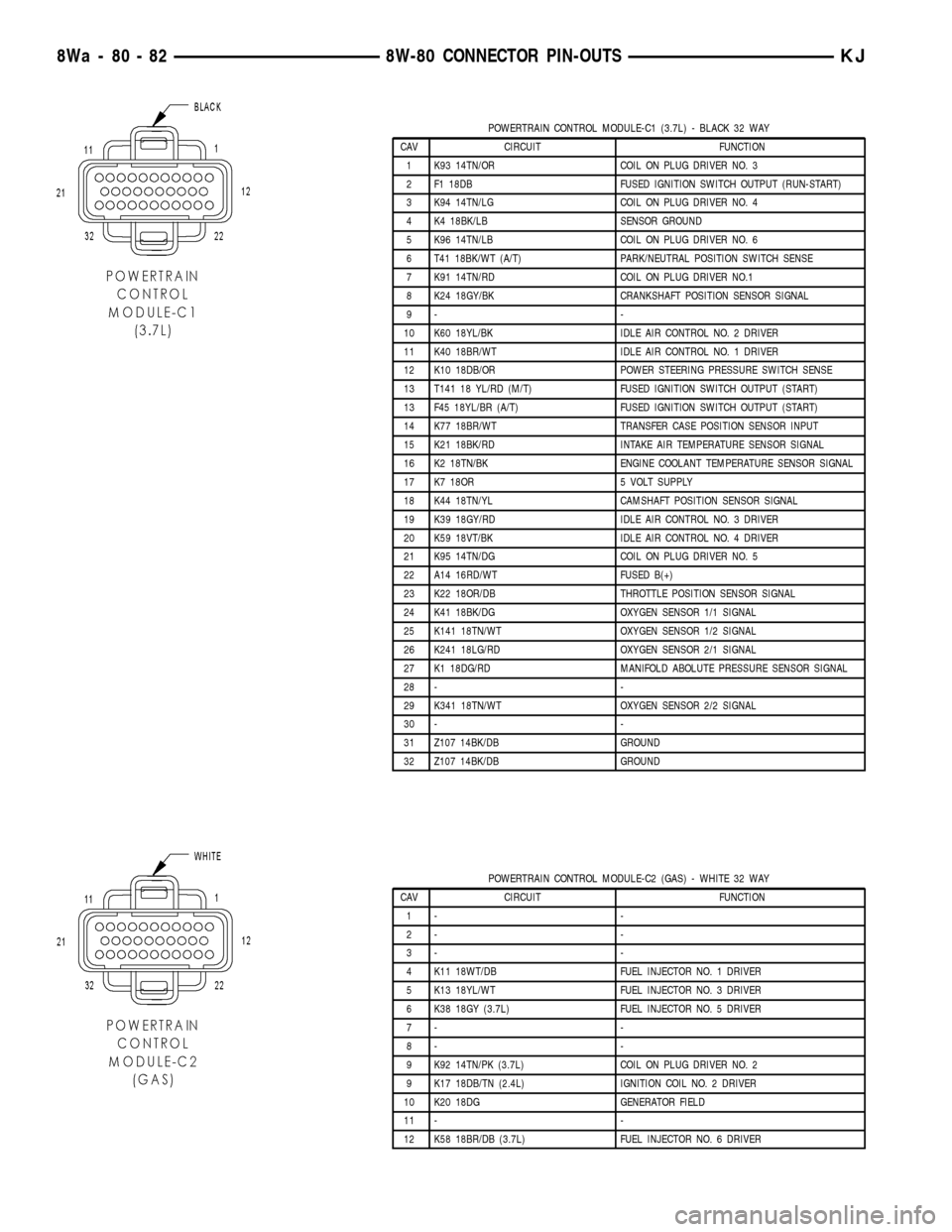
POWERTRAIN CONTROL MODULE-C1 (3.7L) - BLACK 32 WAY
CAV CIRCUIT FUNCTION
1 K93 14TN/OR COIL ON PLUG DRIVER NO. 3
2 F1 18DB FUSED IGNITION SWITCH OUTPUT (RUN-START)
3 K94 14TN/LG COIL ON PLUG DRIVER NO. 4
4 K4 18BK/LB SENSOR GROUND
5 K96 14TN/LB COIL ON PLUG DRIVER NO. 6
6 T41 18BK/WT (A/T) PARK/NEUTRAL POSITION SWITCH SENSE
7 K91 14TN/RD COIL ON PLUG DRIVER NO.1
8 K24 18GY/BK CRANKSHAFT POSITION SENSOR SIGNAL
9- -
10 K60 18YL/BK IDLE AIR CONTROL NO. 2 DRIVER
11 K40 18BR/WT IDLE AIR CONTROL NO. 1 DRIVER
12 K10 18DB/OR POWER STEERING PRESSURE SWITCH SENSE
13 T141 18 YL/RD (M/T) FUSED IGNITION SWITCH OUTPUT (START)
13 F45 18YL/BR (A/T) FUSED IGNITION SWITCH OUTPUT (START)
14 K77 18BR/WT TRANSFER CASE POSITION SENSOR INPUT
15 K21 18BK/RD INTAKE AIR TEMPERATURE SENSOR SIGNAL
16 K2 18TN/BK ENGINE COOLANT TEMPERATURE SENSOR SIGNAL
17 K7 18OR 5 VOLT SUPPLY
18 K44 18TN/YL CAMSHAFT POSITION SENSOR SIGNAL
19 K39 18GY/RD IDLE AIR CONTROL NO. 3 DRIVER
20 K59 18VT/BK IDLE AIR CONTROL NO. 4 DRIVER
21 K95 14TN/DG COIL ON PLUG DRIVER NO. 5
22 A14 16RD/WT FUSED B(+)
23 K22 18OR/DB THROTTLE POSITION SENSOR SIGNAL
24 K41 18BK/DG OXYGEN SENSOR 1/1 SIGNAL
25 K141 18TN/WT OXYGEN SENSOR 1/2 SIGNAL
26 K241 18LG/RD OXYGEN SENSOR 2/1 SIGNAL
27 K1 18DG/RD MANIFOLD ABOLUTE PRESSURE SENSOR SIGNAL
28 - -
29 K341 18TN/WT OXYGEN SENSOR 2/2 SIGNAL
30 - -
31 Z107 14BK/DB GROUND
32 Z107 14BK/DB GROUND
POWERTRAIN CONTROL MODULE-C2 (GAS) - WHITE 32 WAY
CAV CIRCUIT FUNCTION
1- -
2- -
3- -
4 K11 18WT/DB FUEL INJECTOR NO. 1 DRIVER
5 K13 18YL/WT FUEL INJECTOR NO. 3 DRIVER
6 K38 18GY (3.7L) FUEL INJECTOR NO. 5 DRIVER
7- -
8- -
9 K92 14TN/PK (3.7L) COIL ON PLUG DRIVER NO. 2
9 K17 18DB/TN (2.4L) IGNITION COIL NO. 2 DRIVER
10 K20 18DG GENERATOR FIELD
11 - -
12 K58 18BR/DB (3.7L) FUEL INJECTOR NO. 6 DRIVER
8Wa - 80 - 82 8W-80 CONNECTOR PIN-OUTSKJ
Page 1154 of 1803

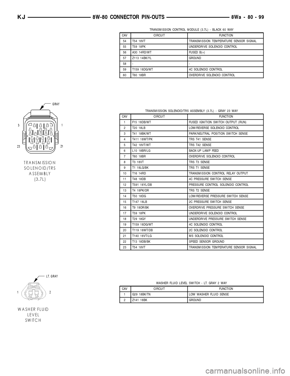
TRANSMISSION CONTROL MODULE (3.7L) - BLACK 60 WAY
CAV CIRCUIT FUNCTION
54 T54 18VT TRANSMISSION TEMPERATURE SENSOR SIGNAL
55 T59 18PK UNDERDRIVE SOLENOID CONTROL
56 A30 14RD/WT FUSED B(+)
57 Z113 14BK/YL GROUND
58 - -
59 T159 18DG/WT 4C SOLENOID CONTROL
60 T60 18BR OVERDRIVE SOLENOID CONTROL
TRANSMISSION SOLENOID/TRS ASSEMBLY (3.7L) - GRAY 23 WAY
CAV CIRCUIT FUNCTION
1 F15 18DB/WT FUSED IGNITION SWITCH OUTPUT (RUN)
2 T20 18LB LOW/REVERSE SOLENOID CONTROL
3 T41 18BK/WT PARK/NEUTRAL POSITION SWITCH SENSE
4 T411 18WT/PK TRS T41 SENSE
5 T42 18VT/WT TRS T42 SENSE
6 L10 18BR/LG BACK-UP LAMP FEED
7 T60 18BR OVERDRIVE SOLENOID CONTROL
8 T3 18VT TRS T3 SENSE
9 T1 18LG/BK TRS T1 SENSE
10 T16 14RD TRANSMISSION CONTROL RELAY OUTPUT
11 T48 18DB 4C PRESSURE SWITCH SENSE
12 T591 18YL/DB PRESSURE CONTROL SOLENOID CONTROL
13 T4 18PK/OR TRS T2 SENSE
14 T50 18DG LOW/REVERSE PRESSURE SWITCH SENSE
15 T147 18LB 2C PRESSURE SWITCH SENSE
16 T9 18OR/BK OVERDRIVE PRESSURE SWITCH SENSE
17 T59 18PK UNDERDRIVE SOLENOID CONTROL
18 T29 18GY UNDERDRIVE PRESSURE SWITCH SENSE
19 T159 18DG/WT 4C SOLENOID CONTROL
20 T119 18WT/DB 2C SOLENOID CONTROL
21 T140 18VT/LG MS SOLENOID CONTROL
22 T13 18DB/BK SPEED SENSOR GROUND
23 T54 18VT TRANSMISSION TEMPERATURE SENSOR SIGNAL
WASHER FLUID LEVEL SWITCH - LT. GRAY 2 WAY
CAV CIRCUIT FUNCTION
1 G29 18BK/TN LOW WASHER FLUID SENSE
2 Z141 18BK GROUND
KJ8W-80 CONNECTOR PIN-OUTS8Wa-80-99
Page 1722 of 1803

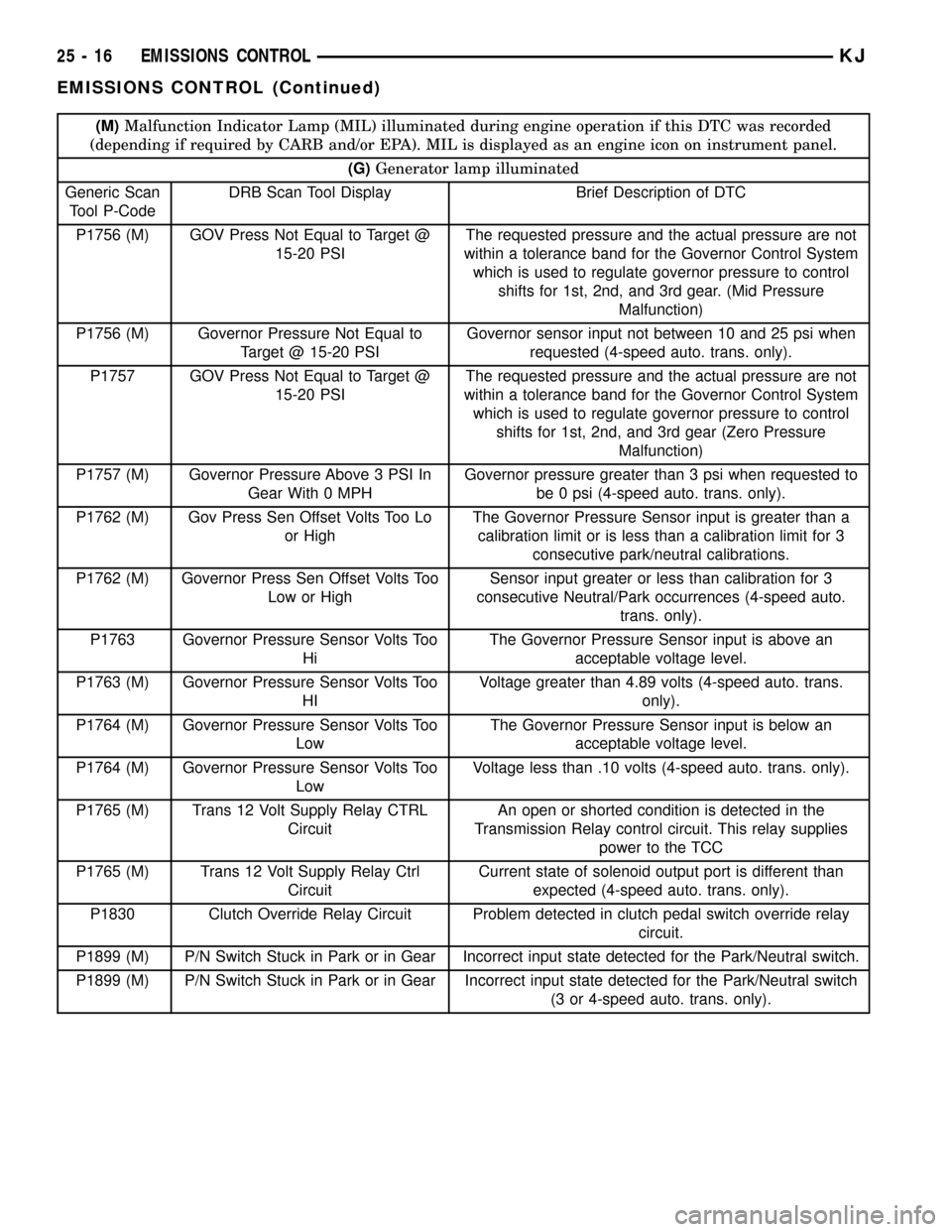
(M)Malfunction Indicator Lamp (MIL) illuminated during engine operation if this DTC was recorded
(depending if required by CARB and/or EPA). MIL is displayed as an engine icon on instrument panel.
(G)Generator lamp illuminated
Generic Scan
Tool P-CodeDRB Scan Tool Display Brief Description of DTC
P1756 (M) GOV Press Not Equal to Target @
15-20 PSIThe requested pressure and the actual pressure are not
within a tolerance band for the Governor Control System
which is used to regulate governor pressure to control
shifts for 1st, 2nd, and 3rd gear. (Mid Pressure
Malfunction)
P1756 (M) Governor Pressure Not Equal to
Target @ 15-20 PSIGovernor sensor input not between 10 and 25 psi when
requested (4-speed auto. trans. only).
P1757 GOV Press Not Equal to Target @
15-20 PSIThe requested pressure and the actual pressure are not
within a tolerance band for the Governor Control System
which is used to regulate governor pressure to control
shifts for 1st, 2nd, and 3rd gear (Zero Pressure
Malfunction)
P1757 (M) Governor Pressure Above 3 PSI In
Gear With 0 MPHGovernor pressure greater than 3 psi when requested to
be 0 psi (4-speed auto. trans. only).
P1762 (M) Gov Press Sen Offset Volts Too Lo
or HighThe Governor Pressure Sensor input is greater than a
calibration limit or is less than a calibration limit for 3
consecutive park/neutral calibrations.
P1762 (M) Governor Press Sen Offset Volts Too
Low or HighSensor input greater or less than calibration for 3
consecutive Neutral/Park occurrences (4-speed auto.
trans. only).
P1763 Governor Pressure Sensor Volts Too
HiThe Governor Pressure Sensor input is above an
acceptable voltage level.
P1763 (M) Governor Pressure Sensor Volts Too
HIVoltage greater than 4.89 volts (4-speed auto. trans.
only).
P1764 (M) Governor Pressure Sensor Volts Too
LowThe Governor Pressure Sensor input is below an
acceptable voltage level.
P1764 (M) Governor Pressure Sensor Volts Too
LowVoltage less than .10 volts (4-speed auto. trans. only).
P1765 (M) Trans 12 Volt Supply Relay CTRL
CircuitAn open or shorted condition is detected in the
Transmission Relay control circuit. This relay supplies
power to the TCC
P1765 (M) Trans 12 Volt Supply Relay Ctrl
CircuitCurrent state of solenoid output port is different than
expected (4-speed auto. trans. only).
P1830 Clutch Override Relay Circuit Problem detected in clutch pedal switch override relay
circuit.
P1899 (M) P/N Switch Stuck in Park or in Gear Incorrect input state detected for the Park/Neutral switch.
P1899 (M) P/N Switch Stuck in Park or in Gear Incorrect input state detected for the Park/Neutral switch
(3 or 4-speed auto. trans. only).
25 - 16 EMISSIONS CONTROLKJ
EMISSIONS CONTROL (Continued)
Page 1726 of 1803

an associated limp in will take two trips to illumi-
nate the MIL.
Refer to the Diagnostic Trouble Codes Description
Charts in this section and the appropriate Power-
train Diagnostic Procedure Manual for diagnostic
procedures.
DESCRIPTION - NON-MONITORED CIRCUITS
The PCM does not monitor the following circuits,
systems and conditions that could have malfunctions
causing driveability problems. The PCM might not
store diagnostic trouble codes for these conditions.
However, problems with these systems may cause the
PCM to store diagnostic trouble codes for other sys-
tems or components. For example, a fuel pressure
problem will not register a fault directly, but could
cause a rich/lean condition or misfire. This could
cause the PCM to store an oxygen sensor or misfire
diagnostic trouble code
FUEL PRESSURE
The fuel pressure regulator controls fuel system
pressure. The PCM cannot detect a clogged fuel
pump inlet filter, clogged in-line fuel filter, or a
pinched fuel supply or return line. However, these
could result in a rich or lean condition causing the
PCM to store an oxygen sensor or fuel system diag-
nostic trouble code.
SECONDARY IGNITION CIRCUIT
The PCM cannot detect an inoperative ignition coil,
fouled or worn spark plugs, ignition cross firing, or
open spark plug cables.
CYLINDER COMPRESSION
The PCM cannot detect uneven, low, or high engine
cylinder compression.
EXHAUST SYSTEM
The PCM cannot detect a plugged, restricted or
leaking exhaust system, although it may set a fuel
system fault.
FUEL INJECTOR MECHANICAL MALFUNCTIONS
The PCM cannot determine if a fuel injector is
clogged, the needle is sticking or if the wrong injectoris installed. However, these could result in a rich or
lean condition causing the PCM to store a diagnostic
trouble code for either misfire, an oxygen sensor, or
the fuel system.
EXCESSIVE OIL CONSUMPTION
Although the PCM monitors engine exhaust oxygen
content when the system is in closed loop, it cannot
determine excessive oil consumption.
THROTTLE BODY AIRFLOW
The PCM cannot detect a clogged or restricted air
cleaner inlet or filter element.
VACUUM ASSIST
The PCM cannot detect leaks or restrictions in the
vacuum circuits of vacuum assisted engine control
system devices. However, these could cause the PCM
to store a MAP sensor diagnostic trouble code and
cause a high idle condition.
PCM SYSTEM GROUND
The PCM cannot determine a poor system ground.
However, one or more diagnostic trouble codes may
be generated as a result of this condition. The mod-
ule should be mounted to the body at all times, also
during diagnostic.
PCM CONNECTOR ENGAGEMENT
The PCM may not be able to determine spread or
damaged connector pins. However, it might store
diagnostic trouble codes as a result of spread connec-
tor pins.
DESCRIPTION - HIGH AND LOW LIMITS
The PCM compares input signal voltages from each
input device with established high and low limits for
the device. If the input voltage is not within limits
and other criteria are met, the PCM stores a diagnos-
tic trouble code in memory. Other diagnostic trouble
code criteria might include engine RPM limits or
input voltages from other sensors or switches that
must be present before verifying a diagnostic trouble
code condition.
DESCRIPTION - LOAD VALUE
ENGINE IDLE/NEUTRAL 2500 RPM/NEUTRAL
All Engines 2% to 8% of Maximum Load 9% to 17% of Maximum Load
25 - 20 EMISSIONS CONTROLKJ
EMISSIONS CONTROL (Continued)