2002 JEEP LIBERTY length
[x] Cancel search: lengthPage 715 of 1803

element where it is gripped by the claws of the
superstructure.
All models have two 47.50 centimeter (18.70 inch)
long front wiper blades with non-replaceable rubber
elements (squeegees). The wiper blades cannot be
adjusted or repaired. If faulty, worn, or damaged the
entire wiper blade unit must be replaced.
OPERATION
The wiper blades are moved back and forth across
the glass by the wiper arms when the wipers are
being operated. The wiper blade superstructure is
the flexible frame that grips the wiper blade element
and evenly distributes the force of the spring-loaded
wiper arm along the length of the element. The com-
bination of the wiper arm force and the flexibility of
the superstructure makes the element conform to
and maintain proper contact with the glass, even as
the blade is moved over the varied curvature that
may be encountered across the glass surface. The
wiper element flexor provides the claws of the blade
superstructure with a rigid, yet flexible component
on the element which can be gripped. The rubber ele-
ment is designed to be stiff enough to maintain an
even cleaning edge as it is drawn across the glass,
yet resilient enough to conform to the glass surface
and flip from one cleaning edge to the other each
time the wiper blade changes directions. The airfoil
used on the driver side wiper blade is designed to
reduce the lifting effect caused by air moving over
the vehicle at higher highway speeds.
REMOVAL
NOTE: The notched end of the wiper element flexor
should always be oriented towards the end of the
wiper blade that is nearest to the wiper pivot.
(1) Lift the front wiper arm to raise the wiper
blade and element off of the glass, until the wiper
arm hinge is in its over-center position.
(2) To remove the wiper blade from the wiper arm,
depress the pivot block latch release tab under the
tip of the arm and slide the blade away from the tip
towards the pivot end of the arm far enough to dis-
engage the pivot block from the hook formation on
the end of the arm (Fig. 13).
(3) Extract the hook formation on the tip of the
wiper arm through the opening in the wiper blade
superstructure just ahead of the wiper blade pivot
block/latch unit.
CAUTION: Do not allow the wiper arm to spring
back against the glass without the wiper blade in
place or the glass may be damaged.(4) Gently lower the tip of the wiper arm onto the
glass.
INSTALLATION
NOTE: The notched end of the wiper element flexor
should always be oriented towards the end of the
wiper blade that is nearest to the wiper pivot.
(1) Lift the front wiper arm off of the windshield
glass, until the wiper arm hinge is in its over-center
position.
(2) Position the front wiper blade near the hook
formation on the tip of the arm with the notched end
of the wiper element flexor oriented towards the end
of the wiper arm that is nearest to the wiper pivot.
(3) Insert the hook formation on the tip of the
wiper arm through the opening in the wiper blade
superstructure ahead of the wiper blade pivot block/
latch unit far enough to engage the pivot block into
the hook (Fig. 13).
(4) Slide the wiper blade pivot block/latch up into
the hook formation on the tip of the wiper arm until
the latch release tab snaps into its locked position.
Latch engagement will be accompanied by an audible
click.
(5) Gently lower the wiper blade onto the glass.
Fig. 13 Front Wiper Blade Remove/Install
1 - SUPERSTRUCTURE
2 - WIPER ARM
3 - PIVOT BLOCK
4 - RELEASE TAB
5 - HOOK
6 - ELEMENT
8R - 14 FRONT WIPERS/WASHERSKJ
FRONT WIPER BLADE (Continued)
Page 735 of 1803
REAR WASHER SYSTEM
The washer system components should be
inspected periodically, not just when washer perfor-
mance problems are experienced. This inspection
should include the following points:
(1) Check for ice or other foreign material in the
washer reservoir. If contaminated, clean and flush
the washer system. (Refer to 8 - ELECTRICAL/
REAR WIPERS/WASHERS - CLEANING).
(2) Inspect the washer plumbing for pinched, leak-
ing, deteriorated, or incorrectly routed hoses and
damaged or disconnected hose fittings. Replace dam-
aged or deteriorated hoses and hose fittings. Leaking
washer hoses can sometimes be repaired by cutting
the hose at the leak and splicing it back together
using an in-line connector fitting. Similarly, sections
of deteriorated hose can be cut out and replaced by
splicing in new sections of hose using in-line connec-
tor fittings. Whenever routing a washer hose or a
wire harness containing a washer hose, it must be
routed away from hot, sharp, or moving parts. Also,
sharp bends that might pinch the washer hose must
be avoided.
REAR CHECK VALVE
DESCRIPTION
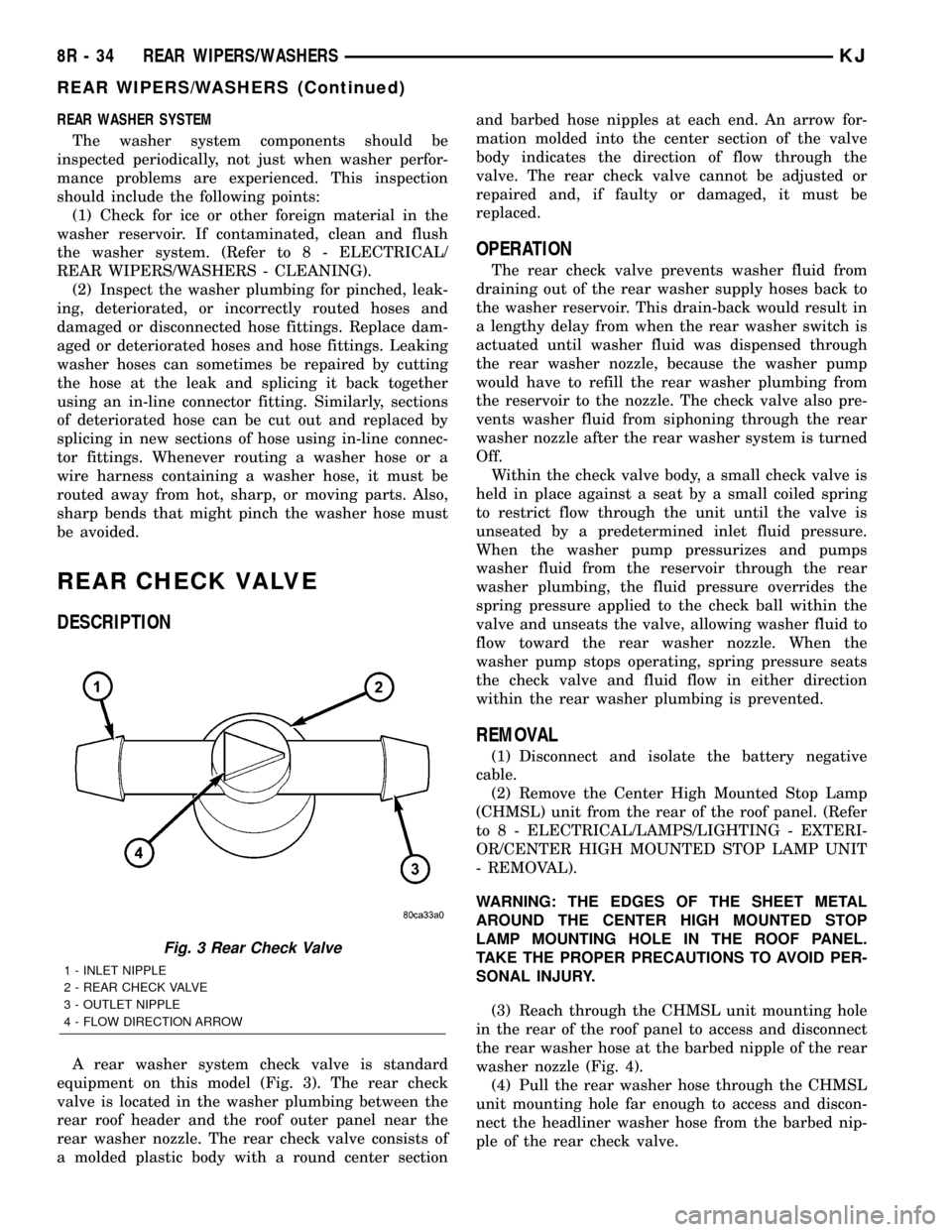
A rear washer system check valve is standard
equipment on this model (Fig. 3). The rear check
valve is located in the washer plumbing between the
rear roof header and the roof outer panel near the
rear washer nozzle. The rear check valve consists of
a molded plastic body with a round center sectionand barbed hose nipples at each end. An arrow for-
mation molded into the center section of the valve
body indicates the direction of flow through the
valve. The rear check valve cannot be adjusted or
repaired and, if faulty or damaged, it must be
replaced.
OPERATION
The rear check valve prevents washer fluid from
draining out of the rear washer supply hoses back to
the washer reservoir. This drain-back would result in
a lengthy delay from when the rear washer switch is
actuated until washer fluid was dispensed through
the rear washer nozzle, because the washer pump
would have to refill the rear washer plumbing from
the reservoir to the nozzle. The check valve also pre-
vents washer fluid from siphoning through the rear
washer nozzle after the rear washer system is turned
Off.
Within the check valve body, a small check valve is
held in place against a seat by a small coiled spring
to restrict flow through the unit until the valve is
unseated by a predetermined inlet fluid pressure.
When the washer pump pressurizes and pumps
washer fluid from the reservoir through the rear
washer plumbing, the fluid pressure overrides the
spring pressure applied to the check ball within the
valve and unseats the valve, allowing washer fluid to
flow toward the rear washer nozzle. When the
washer pump stops operating, spring pressure seats
the check valve and fluid flow in either direction
within the rear washer plumbing is prevented.
REMOVAL
(1) Disconnect and isolate the battery negative
cable.
(2) Remove the Center High Mounted Stop Lamp
(CHMSL) unit from the rear of the roof panel. (Refer
to 8 - ELECTRICAL/LAMPS/LIGHTING - EXTERI-
OR/CENTER HIGH MOUNTED STOP LAMP UNIT
- REMOVAL).
WARNING: THE EDGES OF THE SHEET METAL
AROUND THE CENTER HIGH MOUNTED STOP
LAMP MOUNTING HOLE IN THE ROOF PANEL.
TAKE THE PROPER PRECAUTIONS TO AVOID PER-
SONAL INJURY.
(3) Reach through the CHMSL unit mounting hole
in the rear of the roof panel to access and disconnect
the rear washer hose at the barbed nipple of the rear
washer nozzle (Fig. 4).
(4) Pull the rear washer hose through the CHMSL
unit mounting hole far enough to access and discon-
nect the headliner washer hose from the barbed nip-
ple of the rear check valve.
Fig. 3 Rear Check Valve
1 - INLET NIPPLE
2 - REAR CHECK VALVE
3 - OUTLET NIPPLE
4 - FLOW DIRECTION ARROW
8R - 34 REAR WIPERS/WASHERSKJ
REAR WIPERS/WASHERS (Continued)
Page 737 of 1803
headliner hose is glued to top of the headliner and
routed along the right roof side rail to the rear of the
vehicle. At the rear of the vehicle, the headliner hose
passes through a hole at the rear portion of the roof
rear inner header panel and is connected to the rear
check valve. From the rear check valve, there is a
short section of hose that connects the rear check
valve to the rear washer nozzle.
Washer hose is available for service only as roll
stock, which must then be cut to length. The head-
liner washer hose is integral to the headliner unit
and, if faulty or damaged, the headliner unit must be
replaced. However, the headliner hose is marked
with a white cut line on the A-pillar where the hose
should be cut and spliced with a plastic in-line con-
nector fitting to facilitate headliner removal without
the need to remove the instrument panel. (Refer to
23 - BODY/INTERIOR/HEADLINER - REMOVAL
AND INSTALLATION). The molded plastic washer
hose fittings cannot be repaired. If these fittings are
faulty or damaged, they must be replaced.
OPERATION
Washer fluid in the washer reservoir is pressurized
and fed by the washer pump/motor through the rear
washer system plumbing and fittings to the rear
washer nozzle located on the roof panel above the
rear flip-up glass opening. Whenever routing the
washer hose or a wire harness containing a washer
hose, it must be routed away from hot, sharp, or
moving parts; and, sharp bends that might pinch the
hose must be avoided.
REAR WASHER NOZZLE
DESCRIPTION
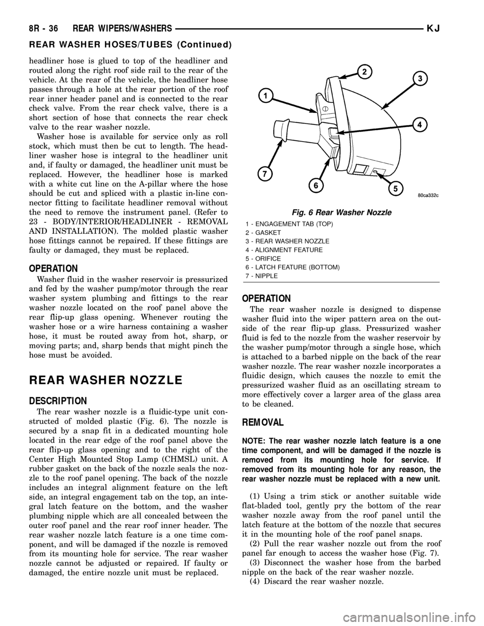
The rear washer nozzle is a fluidic-type unit con-
structed of molded plastic (Fig. 6). The nozzle is
secured by a snap fit in a dedicated mounting hole
located in the rear edge of the roof panel above the
rear flip-up glass opening and to the right of the
Center High Mounted Stop Lamp (CHMSL) unit. A
rubber gasket on the back of the nozzle seals the noz-
zle to the roof panel opening. The back of the nozzle
includes an integral alignment feature on the left
side, an integral engagement tab on the top, an inte-
gral latch feature on the bottom, and the washer
plumbing nipple which are all concealed between the
outer roof panel and the rear roof inner header. The
rear washer nozzle latch feature is a one time com-
ponent, and will be damaged if the nozzle is removed
from its mounting hole for service. The rear washer
nozzle cannot be adjusted or repaired. If faulty or
damaged, the entire nozzle unit must be replaced.
OPERATION
The rear washer nozzle is designed to dispense
washer fluid into the wiper pattern area on the out-
side of the rear flip-up glass. Pressurized washer
fluid is fed to the nozzle from the washer reservoir by
the washer pump/motor through a single hose, which
is attached to a barbed nipple on the back of the rear
washer nozzle. The rear washer nozzle incorporates a
fluidic design, which causes the nozzle to emit the
pressurized washer fluid as an oscillating stream to
more effectively cover a larger area of the glass area
to be cleaned.
REMOVAL
NOTE: The rear washer nozzle latch feature is a one
time component, and will be damaged if the nozzle is
removed from its mounting hole for service. If
removed from its mounting hole for any reason, the
rear washer nozzle must be replaced with a new unit.
(1) Using a trim stick or another suitable wide
flat-bladed tool, gently pry the bottom of the rear
washer nozzle away from the roof panel until the
latch feature at the bottom of the nozzle that secures
it in the mounting hole of the roof panel snaps.
(2) Pull the rear washer nozzle out from the roof
panel far enough to access the washer hose (Fig. 7).
(3) Disconnect the washer hose from the barbed
nipple on the back of the rear washer nozzle.
(4) Discard the rear washer nozzle.
Fig. 6 Rear Washer Nozzle
1 - ENGAGEMENT TAB (TOP)
2 - GASKET
3 - REAR WASHER NOZZLE
4 - ALIGNMENT FEATURE
5 - ORIFICE
6 - LATCH FEATURE (BOTTOM)
7 - NIPPLE
8R - 36 REAR WIPERS/WASHERSKJ
REAR WASHER HOSES/TUBES (Continued)
Page 740 of 1803
(4) Install and tighten the nut that secures the
rear wiper arm to the rear wiper motor output shaft.
Tighten the nut to 18 N´m (13 ft. lbs.).
(5) Close the rear wiper arm pivot cover.
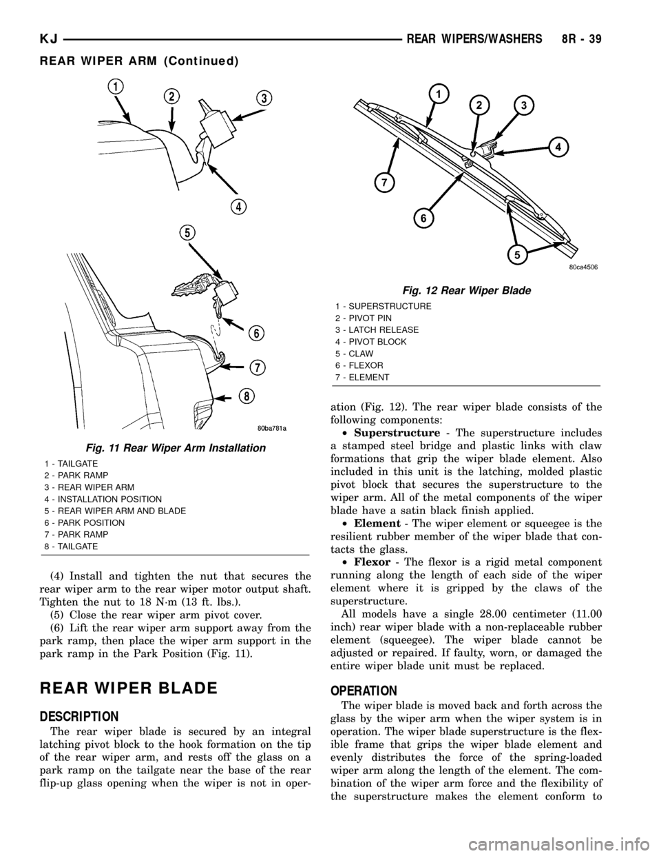
(6) Lift the rear wiper arm support away from the
park ramp, then place the wiper arm support in the
park ramp in the Park Position (Fig. 11).
REAR WIPER BLADE
DESCRIPTION
The rear wiper blade is secured by an integral
latching pivot block to the hook formation on the tip
of the rear wiper arm, and rests off the glass on a
park ramp on the tailgate near the base of the rear
flip-up glass opening when the wiper is not in oper-ation (Fig. 12). The rear wiper blade consists of the
following components:
²Superstructure- The superstructure includes
a stamped steel bridge and plastic links with claw
formations that grip the wiper blade element. Also
included in this unit is the latching, molded plastic
pivot block that secures the superstructure to the
wiper arm. All of the metal components of the wiper
blade have a satin black finish applied.
²Element- The wiper element or squeegee is the
resilient rubber member of the wiper blade that con-
tacts the glass.
²Flexor- The flexor is a rigid metal component
running along the length of each side of the wiper
element where it is gripped by the claws of the
superstructure.
All models have a single 28.00 centimeter (11.00
inch) rear wiper blade with a non-replaceable rubber
element (squeegee). The wiper blade cannot be
adjusted or repaired. If faulty, worn, or damaged the
entire wiper blade unit must be replaced.
OPERATION
The wiper blade is moved back and forth across the
glass by the wiper arm when the wiper system is in
operation. The wiper blade superstructure is the flex-
ible frame that grips the wiper blade element and
evenly distributes the force of the spring-loaded
wiper arm along the length of the element. The com-
bination of the wiper arm force and the flexibility of
the superstructure makes the element conform to
Fig. 11 Rear Wiper Arm Installation
1 - TAILGATE
2 - PARK RAMP
3 - REAR WIPER ARM
4 - INSTALLATION POSITION
5 - REAR WIPER ARM AND BLADE
6 - PARK POSITION
7 - PARK RAMP
8 - TAILGATE
Fig. 12 Rear Wiper Blade
1 - SUPERSTRUCTURE
2 - PIVOT PIN
3 - LATCH RELEASE
4 - PIVOT BLOCK
5 - CLAW
6 - FLEXOR
7 - ELEMENT
KJREAR WIPERS/WASHERS 8R - 39
REAR WIPER ARM (Continued)
Page 760 of 1803

INSTALLATION
(1) Insert the removed terminal in the same cavity
on the repair connector.
(2) Repeat steps for each terminal in the connec-
tor, being sure that all wires are inserted into the
proper cavities. For additional connector pin-out
identification, refer to the wiring diagrams.
(3) When the connector is re-assembled, the sec-
ondary terminal lock must be placed in the locked
position to prevent terminal push out.
(4) Replace dress cover (if applicable).
(5) Connect connector to its mating half/compo-
nent.
(6) Connect battery and test all affected systems.
DIODE
REMOVAL
(1) Disconnect the battery.
(2) Locate the diode in the harness, and remove
the protective covering.
(3) Remove the diode from the harness, pay atten-
tion to the current flow direction (Fig. 13).
INSTALLATION
(1) Remove the insulation from the wires in the
harness. Only remove enough insulation to solder in
the new diode.(2) Install the new diode in the harness, making
sure current flow is correct. If necessary, refer to the
appropriate wiring diagram for current flow (Fig. 13).
(3) Solder the connection together using rosin core
type solder only.Do not use acid core solder.
(4) Tape the diode to the harness using electrical
tape. Make sure the diode is completely sealed from
the elements.
(5) Re-connect the battery and test affected sys-
tems.
TERMINAL
REMOVAL
(1) Follow steps for removing terminals described
in the connector removal section.
(2) Cut the wire 6 inches from the back of the con-
nector.
INSTALLATION
(1) Select a wire from the terminal repair kit that
best matches the color and gage of the wire being
repaired.
(2) Cut the repair wire to the proper length and
remove one±half (1/2) inch of insulation.
(3) Splice the repair wire to the wire harness (see
wire splicing procedure).
(4) Insert the repaired wire into the connector.
(5) Install the connector locking wedge, if required,
and reconnect the connector to its mating half/compo-
nent.
(6) Re-tape the wire harness starting at 1±1/2
inches behind the connector and 2 inches past the
repair.
(7) Connect battery and test all affected systems.
WIRE
STANDARD PROCEDURE - WIRE SPLICING
When splicing a wire, it is important that the cor-
rect gage be used as shown in the wiring diagrams.
(1) Remove one-half (1/2) inch of insulation from
each wire that needs to be spliced.
(2) Place a piece of adhesive lined heat shrink tub-
ing on one side of the wire. Make sure the tubing will
be long enough to cover and seal the entire repair
area.
Fig. 13 DIODE IDENTIFICATION
1 - CURRENT FLOW
2 - BAND AROUND DIODE INDICATES CURRENT FLOW
3 - DIODE AS SHOWN IN THE DIAGRAMS
KJ8W-01 WIRING DIAGRAM INFORMATION8Wa-01-13
CONNECTOR (Continued)
Page 1229 of 1803
DESCRIPTION SPECIFICATION
VALVE TIMING
Intake
Opens (ATDC) 3.6É
Closes (ATDC) 247.1É
Duration 243.5É
Exhaust
Opens (BTDC) 232.5É
Closes (ATDC) 21.2É
Duration 253.70É
Valve Overlap 17.6É
VA LV E S
Face Angle 45É - 45.5É
Head Diameter
Intake 48.52 - 48.78 mm
(1.9103 - 1.9205 in.)
Exhaust 36.87 - 37.13 mm
1.4516 - 1.4618 in.)
Length (Overall)
Intake 113.45 - 114.21 mm
(4.4666 - 4.4965)
Exhaust 114.92 - 115.68 mm
(4.5244 - 4.5543 in.)
Stem Diameter
Intake 6.931 - 6.957 mm
(0.2729 - 0.2739 in.)
Exhaust 6.902 - 6.928 mm
(0.2717 - 0.2728 in.)
Stem - to - Guide
Clearance
Intake 0.018 - 0.069 mm
(0.0008 - 0.0028 in.)
Exhaust 0.047 - 0.098 mm
(0.0019 - 0.0039 in.)
Max. Allowable Stem -
to -
Guide Clearance
(Rocking
Method)
Intake 0.069 mm (0.0028 in.)
Exhaust 0.098 mm (0.0039 in.)DESCRIPTION SPECIFICATION
Valve Lift (Zero Lash)
Intake 12.00 mm (0.472 in.)
Exhaust 10.90 mm (0.4292 in.)
VALVE SPRING
Free Lenght (Approx)
Intake and Exhaust 48.92 mm (1.9260 in.)
Spring Force (Valve
Closed)
Intake and Exhaust 361.0 - 399.0 N @ 40.12
mm
(81.15 - 89.70 lbs. @
1.5795 in.)
Spring Force (Valve
Open)
Intake and Exhaust 984.0 - 1076.0 N @
28.12 mm
221.2 - 241.9 lbs. @
1.107 in.)
Number of Coils
Intake and Exhaust 7.30
Wire Diameter
Intake and Exhaust 4.77 ý 3.80mm
(0.1878 - 0.1496 in.)
Installed Height (Spring
Seat to Bottom of
Retainer)
Nominal
Intake 41.11 mm (1.619 in.)
Exhaust 41.13 mm (1.619 in.)
CYLINDER HEAD
Gasket Thickness
(Compressed) 0.7 mm (0.0276 in.)
Valve Seat Angle 44.5É - 45.0É
Valve Seat Runout (MAX) 0.051 mm (0.002 in.)
Valve Seat Width
Intake 1.75 - 2.36 mm
(0.0698 - 0.0928 in.)
Exhaust 1.71 - 2.32 mm
(0.0673 - 0.0911 in.)
Guide Bore Diameter
(Std.)6.975 - 7.00 mm
(0.2747 - 0.2756 in.)
9 - 14 ENGINE - 3.7LKJ
ENGINE - 3.7L (Continued)
Page 1243 of 1803
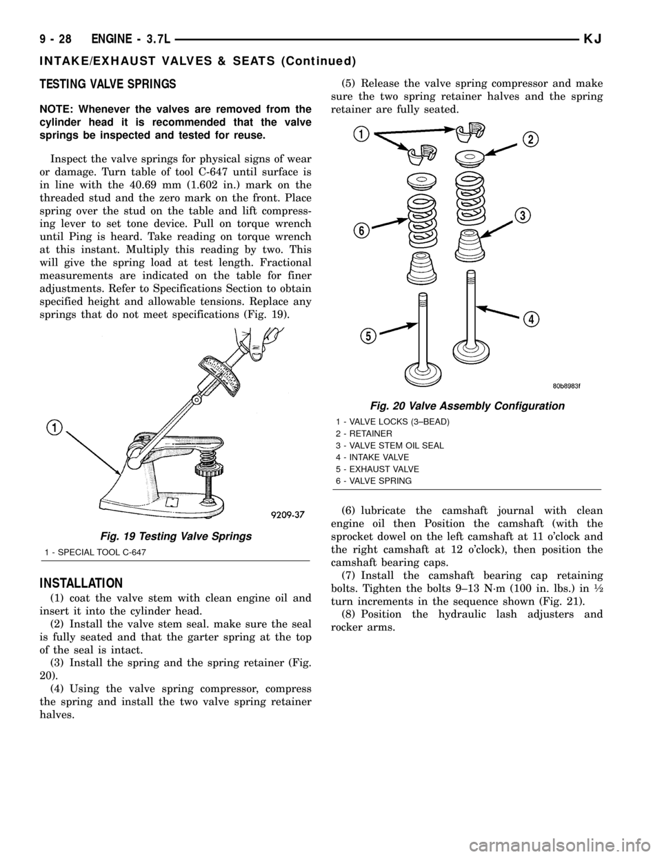
TESTING VALVE SPRINGS
NOTE: Whenever the valves are removed from the
cylinder head it is recommended that the valve
springs be inspected and tested for reuse.
Inspect the valve springs for physical signs of wear
or damage. Turn table of tool C-647 until surface is
in line with the 40.69 mm (1.602 in.) mark on the
threaded stud and the zero mark on the front. Place
spring over the stud on the table and lift compress-
ing lever to set tone device. Pull on torque wrench
until Ping is heard. Take reading on torque wrench
at this instant. Multiply this reading by two. This
will give the spring load at test length. Fractional
measurements are indicated on the table for finer
adjustments. Refer to Specifications Section to obtain
specified height and allowable tensions. Replace any
springs that do not meet specifications (Fig. 19).
INSTALLATION
(1) coat the valve stem with clean engine oil and
insert it into the cylinder head.
(2) Install the valve stem seal. make sure the seal
is fully seated and that the garter spring at the top
of the seal is intact.
(3) Install the spring and the spring retainer (Fig.
20).
(4) Using the valve spring compressor, compress
the spring and install the two valve spring retainer
halves.(5) Release the valve spring compressor and make
sure the two spring retainer halves and the spring
retainer are fully seated.
(6) lubricate the camshaft journal with clean
engine oil then Position the camshaft (with the
sprocket dowel on the left camshaft at 11 o'clock and
the right camshaft at 12 o'clock), then position the
camshaft bearing caps.
(7) Install the camshaft bearing cap retaining
bolts. Tighten the bolts 9±13 N´m (100 in. lbs.) in ó
turn increments in the sequence shown (Fig. 21).
(8) Position the hydraulic lash adjusters and
rocker arms.
Fig. 19 Testing Valve Springs
1 - SPECIAL TOOL C-647
Fig. 20 Valve Assembly Configuration
1 - VALVE LOCKS (3±BEAD)
2 - RETAINER
3 - VALVE STEM OIL SEAL
4 - INTAKE VALVE
5 - EXHAUST VALVE
6 - VALVE SPRING
9 - 28 ENGINE - 3.7LKJ
INTAKE/EXHAUST VALVES & SEATS (Continued)
Page 1251 of 1803
NOTE: Check for sharp edges on the keeper
grooves. Remove any burrs from the valve stem
before removing the valve from the cylinder head.
(7) Remove the valve from the cylinder head.
NOTE: The valve stem seals are common between
intake and exhaust.
(8) Remove the valve stem seal. Mark the valve for
proper installation.
TESTING VALVE SPRINGS
NOTE: Whenever the valves are removed from the
cylinder head it is recommended that the valve
springs be inspected and tested for reuse.
Inspect the valve springs for physical signs of wear
or damage. Turn table of tool C-647 until surface is
in line with the 40.69 mm (1.602 in.) mark on the
threaded stud and the zero mark on the front. Place
spring over the stud on the table and lift compress-
ing lever to set tone device. Pull on torque wrench
until Ping is heard. Take reading on torque wrench
at this instant. Multiply this reading by two. This
will give the spring load at test length. Fractional
measurements are indicated on the table for finer
adjustments. Refer to Specifications Section to obtain
specified height and allowable tensions. Replace any
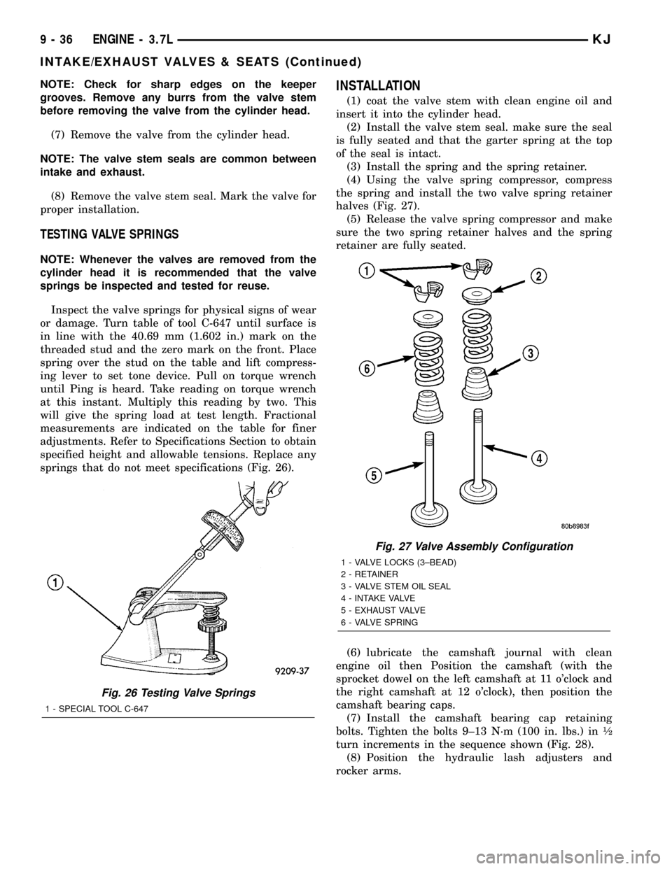
springs that do not meet specifications (Fig. 26).
INSTALLATION
(1) coat the valve stem with clean engine oil and
insert it into the cylinder head.
(2) Install the valve stem seal. make sure the seal
is fully seated and that the garter spring at the top
of the seal is intact.
(3) Install the spring and the spring retainer.
(4) Using the valve spring compressor, compress
the spring and install the two valve spring retainer
halves (Fig. 27).
(5) Release the valve spring compressor and make
sure the two spring retainer halves and the spring
retainer are fully seated.
(6) lubricate the camshaft journal with clean
engine oil then Position the camshaft (with the
sprocket dowel on the left camshaft at 11 o'clock and
the right camshaft at 12 o'clock), then position the
camshaft bearing caps.
(7) Install the camshaft bearing cap retaining
bolts. Tighten the bolts 9±13 N´m (100 in. lbs.) in ó
turn increments in the sequence shown (Fig. 28).
(8) Position the hydraulic lash adjusters and
rocker arms.
Fig. 26 Testing Valve Springs
1 - SPECIAL TOOL C-647
Fig. 27 Valve Assembly Configuration
1 - VALVE LOCKS (3±BEAD)
2 - RETAINER
3 - VALVE STEM OIL SEAL
4 - INTAKE VALVE
5 - EXHAUST VALVE
6 - VALVE SPRING
9 - 36 ENGINE - 3.7LKJ
INTAKE/EXHAUST VALVES & SEATS (Continued)