2002 JEEP LIBERTY injector
[x] Cancel search: injectorPage 1225 of 1803
²Tapping the hole with a special Heli-Coil Tap, or
equivalent.
²Installing an insert into the tapped hole to bring
the hole back to its original thread size.
STANDARD PROCEDURE - ENGINE CORE AND
OIL GALLERY PLUGS
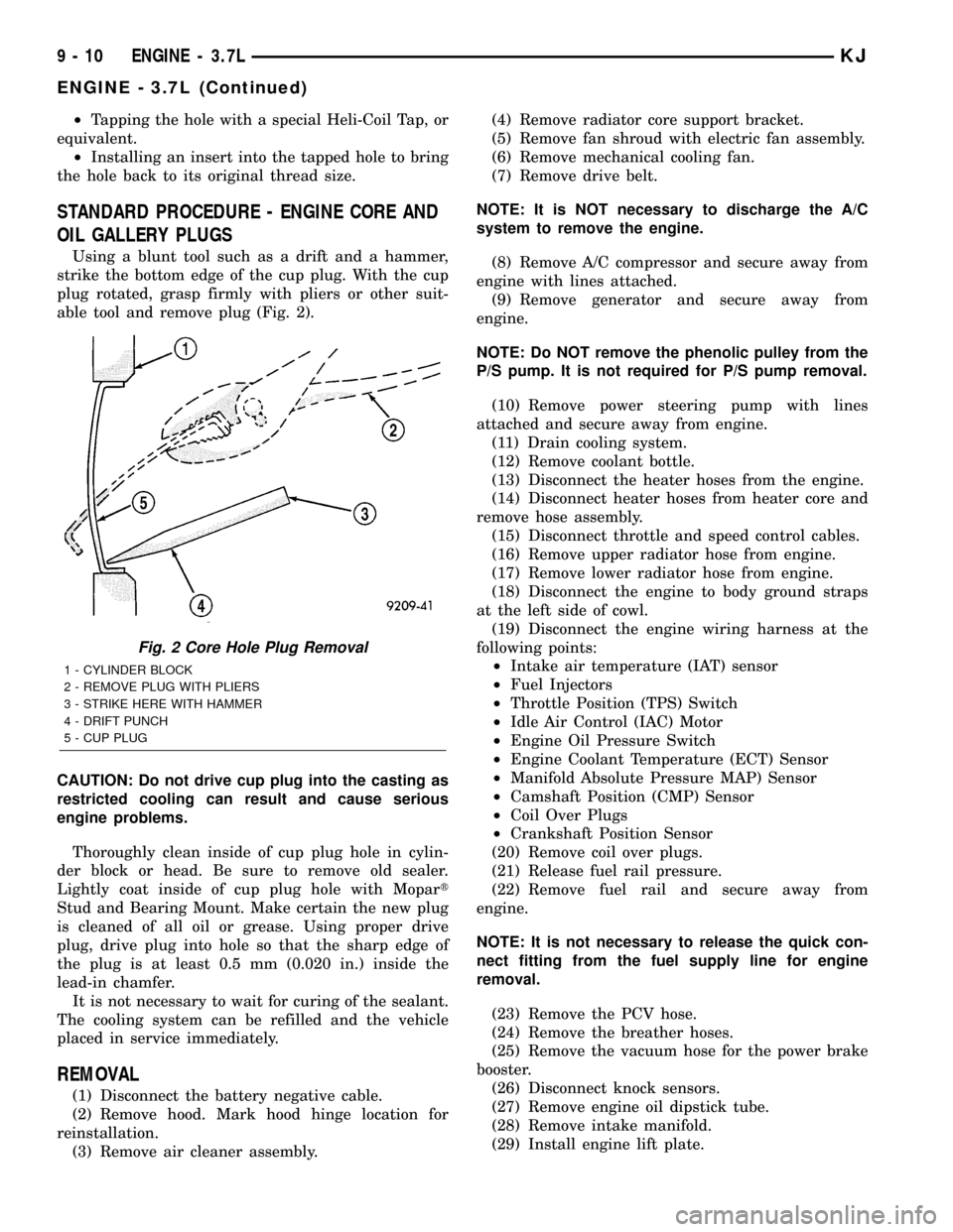
Using a blunt tool such as a drift and a hammer,
strike the bottom edge of the cup plug. With the cup
plug rotated, grasp firmly with pliers or other suit-
able tool and remove plug (Fig. 2).
CAUTION: Do not drive cup plug into the casting as
restricted cooling can result and cause serious
engine problems.
Thoroughly clean inside of cup plug hole in cylin-
der block or head. Be sure to remove old sealer.
Lightly coat inside of cup plug hole with Mopart
Stud and Bearing Mount. Make certain the new plug
is cleaned of all oil or grease. Using proper drive
plug, drive plug into hole so that the sharp edge of
the plug is at least 0.5 mm (0.020 in.) inside the
lead-in chamfer.
It is not necessary to wait for curing of the sealant.
The cooling system can be refilled and the vehicle
placed in service immediately.
REMOVAL
(1) Disconnect the battery negative cable.
(2) Remove hood. Mark hood hinge location for
reinstallation.
(3) Remove air cleaner assembly.(4) Remove radiator core support bracket.
(5) Remove fan shroud with electric fan assembly.
(6) Remove mechanical cooling fan.
(7) Remove drive belt.
NOTE: It is NOT necessary to discharge the A/C
system to remove the engine.
(8) Remove A/C compressor and secure away from
engine with lines attached.
(9) Remove generator and secure away from
engine.
NOTE: Do NOT remove the phenolic pulley from the
P/S pump. It is not required for P/S pump removal.
(10) Remove power steering pump with lines
attached and secure away from engine.
(11) Drain cooling system.
(12) Remove coolant bottle.
(13) Disconnect the heater hoses from the engine.
(14) Disconnect heater hoses from heater core and
remove hose assembly.
(15) Disconnect throttle and speed control cables.
(16) Remove upper radiator hose from engine.
(17) Remove lower radiator hose from engine.
(18) Disconnect the engine to body ground straps
at the left side of cowl.
(19) Disconnect the engine wiring harness at the
following points:
²Intake air temperature (IAT) sensor
²Fuel Injectors
²Throttle Position (TPS) Switch
²Idle Air Control (IAC) Motor
²Engine Oil Pressure Switch
²Engine Coolant Temperature (ECT) Sensor
²Manifold Absolute Pressure MAP) Sensor
²Camshaft Position (CMP) Sensor
²Coil Over Plugs
²Crankshaft Position Sensor
(20) Remove coil over plugs.
(21) Release fuel rail pressure.
(22) Remove fuel rail and secure away from
engine.
NOTE: It is not necessary to release the quick con-
nect fitting from the fuel supply line for engine
removal.
(23) Remove the PCV hose.
(24) Remove the breather hoses.
(25) Remove the vacuum hose for the power brake
booster.
(26) Disconnect knock sensors.
(27) Remove engine oil dipstick tube.
(28) Remove intake manifold.
(29) Install engine lift plate.
Fig. 2 Core Hole Plug Removal
1 - CYLINDER BLOCK
2 - REMOVE PLUG WITH PLIERS
3 - STRIKE HERE WITH HAMMER
4 - DRIFT PUNCH
5 - CUP PLUG
9 - 10 ENGINE - 3.7LKJ
ENGINE - 3.7L (Continued)
Page 1226 of 1803
NOTE: Recheck bolt torque for engine lift plate
before removing engine.
(30) Secure the left and right engine wiring har-
nesses away from engine.
(31) Raise vehicle.
(32) Disconnect oxygen sensor wiring.
(33) Disconnect crankshaft postion sensor.
(34) Disconnect the engine block heater power
cable, if equipped.
(35) Disconnect the front propshaft at the front
differential and secure out of way.
NOTE: It is necessary to disconnect the front prop-
shaft for access to the starter and left side exhaust
flange.
(36) Remove the starter.
(37) Remove the ground straps from the left and
right side of the block.
(38) Disconnect the right and left exhaust pipes at
the manifolds and from the crossover, and remove
from the vehicle.
NOTE: The exhaust clamps at the manifolds cannot
be reused. New clamps must be used or leaks may
occur.
NOTE: For manual transmission vehicles, the trans-
mission must be removed from the vehicle, before
the engine can be removed. The manual transmis-
sion will contact the floorpan before the engine
clears the motor mounts, so it must be removed.
(39) Remove the structural cover.
(40) Remove torque convertor bolts, and mark
location for reassembly.
(41) Remove transmission bellhousing to engine
bolts.
(42) Loosen left and right engine mount thru bolts.
NOTE: It is not necessary to completely remove
engine mount thru bolts, for engine removal.
(43) Lower the vehicle.
(44) Support the transmission with a suitable jack.
(45) Connect a suitable engine hoist to the engine
lift plate.
(46) Remove engine from vehicle.
INSTALLATION
(1) Position the engine in the vehicle.
(2) Install both left and right side engine mounts
onto engine.
(3) Raise the vehicle.(4) Install the transmission bellhousing to engine
mounting bolts. Tighten the bolts to 41 N´m (30ft.
lbs.).
(5) Tighten the engine mount thru bolts.
(6) Install the torque convertor bolts.
(7) Connect the ground straps on the left and right
side of the engine.
(8) Install the starter.
(9) Connect the crankshaft position sensor.
(10) Install the engine block heater power cable, if
equipped.
CAUTION: The structural cover requires a specific
torque sequence. Failure to follow this sequence
may cause severe damage to the cover.
(11) Install the structural cover.
NOTE: New clamps must be used on exhaust man-
ifold flanges. Failure to use new clamps may result
in exhaust leaks.
(12) Install the left and right exhaust pipes.
(13) Connect the left and right oxygen sensors.
(14) Lower vehicle.
(15) Remove the engine lift plate.
(16) Connect the knock sensors.
(17) Connect the engine to body ground straps at
the left side of the cowl.
(18) Install the intake manifold.
(19) Install the engine oil dipstick tube.
(20) Install the power brake booster vacuum hose.
(21) Install the breather hoses.
(22) Install the PCV hose.
(23) Install the fuel rail.
(24) Install the coil over plugs.
(25) Connect the engine wiring harness at the fol-
lowing points:
²Intake air temperature (IAT) sensor
²Fuel Injectors
²Throttle Position (TPS) Switch
²Idle Air Control (IAC) Motor
²Engine Oil Pressure Switch
²Engine Coolant Temperature (ECT) Sensor
²Manifold Absolute Pressure MAP) Sensor
²Camshaft Position (CMP) Sensor
²Coil Over Plugs
²Crankshaft Position Sensor
(26) Connect lower radiator hose.
(27) Connect upper radiator hose.
(28) Connect throttle and speed control cables.
(29) Install the heater hose assembly.
(30) Install coolant recovery bottle.
(31) Install the power steering pump.
(32) Install the generator.
(33) Install the A/C compressor.
(34) Install the drive belt.
KJENGINE - 3.7L 9 - 11
ENGINE - 3.7L (Continued)
Page 1240 of 1803
NOTE: When the camshaft is removed the rocker
arms may slide downward, mark the rocker arms
before removing camshaft.
(9) Remove the camshaft bearing caps and the
camshaft.
INSTALLATION
(1) Lubricate camshaft journals with clean engine
oil.
NOTE: Position the left side camshaft so that the
camshaft sprocket dowel is near the 1 o'clock posi-
tion, This will place the camshaft at the neutral
position easing the installation of the camshaft
bearing caps.
(2) Position the camshaft into the cylinder head.
(3) Install the camshaft bearing caps, hand tighten
the retaining bolts.
NOTE: Caps should be installed so that the
stamped numbers on the caps are in numerical
order, ( 1 thru 4 ) from the front to the rear of the
engine. All caps should be installed so that the
stamped arrows on the caps point toward the front
of the engine.
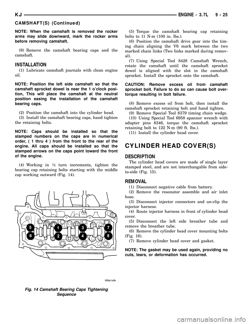
(4) Working in ó turn increments, tighten the
bearing cap retaining bolts starting with the middle
cap working outward (Fig. 14).(5) Torque the camshaft bearing cap retaining
bolts to 11 N´m (100 in. lbs.).
(6) Position the camshaft drive gear into the tim-
ing chain aligning the V6 mark between the two
marked chain links (Two links marked during remov-
al).
(7) Using Special Tool 8428 Camshaft Wrench,
rotate the camshaft until the camshaft sprocket
dowel is aligned with the slot in the camshaft
sprocket. Install the sprocket onto the camshaft.
CAUTION: Remove excess oil from camshaft
sprocket bolt. Failure to do so can cause bolt over-
torque resulting in bolt failure.
(8) Remove excess oil from bolt, then install the
camshaft sprocket retaining bolt and hand tighten.
(9) Remove Special Tool 8379 timing chain wedge.
(10) Using Special Tool 6958 spanner wrench with
adapter pins 8346, torque the camshaft sprocket
retaining bolt to 122 N´m (90 ft. lbs.).
(11) Install the cylinder head cover.
CYLINDER HEAD COVER(S)
DESCRIPTION
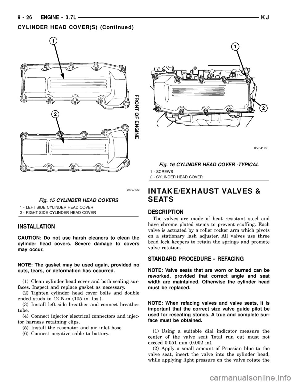
The cylinder head covers are made of single layer
stamped steel, and are not interchangable from side-
to-side (Fig. 15).
REMOVAL
(1) Disconnect negative cable from battery.
(2) Remove the resonator assemble and air inlet
hose.
(3) Disconnect injector connectors and un-clip the
injector harness.
(4) Route injector harness in front of cylinder head
cover.
(5) Disconnect the left side breather tube and
remove the breather tube.
(6) Remove the cylinder head cover mounting bolts
(Fig. 16).
(7) Remove cylinder head cover and gasket.
NOTE: The gasket may be used again, providing no
cuts, tears, or deformation has occurred.
Fig. 14 Camshaft Bearing Caps Tightening
Sequence
KJENGINE - 3.7L 9 - 25
CAMSHAFT(S) (Continued)
Page 1241 of 1803
INSTALLATION
CAUTION: Do not use harsh cleaners to clean the
cylinder head covers. Severe damage to covers
may occur.
NOTE: The gasket may be used again, provided no
cuts, tears, or deformation has occurred.
(1) Clean cylinder head cover and both sealing sur-
faces. Inspect and replace gasket as necessary.
(2) Tighten cylinder head cover bolts and double
ended studs to 12 N´m (105 in. lbs.).
(3) Install left side breather and connect breather
tube.
(4) Connect injector electrical connectors and injec-
tor harness retaining clips.
(5) Install the resonator and air inlet hose.
(6) Connect negative cable to battery.
INTAKE/EXHAUST VALVES &
SEATS
DESCRIPTION
The valves are made of heat resistant steel and
have chrome plated stems to prevent scuffing. Each
valve is actuated by a roller rocker arm which pivots
on a stationary lash adjuster. All valves use three
bead lock keepers to retain the springs and promote
valve rotation.
STANDARD PROCEDURE - REFACING
NOTE: Valve seats that are worn or burned can be
reworked, provided that correct angle and seat
width are maintained. Otherwise the cylinder head
must be replaced.
NOTE: When refacing valves and valve seats, it is
important that the correct size valve guide pilot be
used for reseating stones. A true and complete sur-
face must be obtained.
(1) Using a suitable dial indicator measure the
center of the valve seat Total run out must not
exceed 0.051 mm (0.002 in).
(2) Apply a small amount of Prussian blue to the
valve seat, insert the valve into the cylinder head,
while applying light pressure on the valve rotate the
Fig. 15 CYLINDER HEAD COVERS
1 - LEFT SIDE CYLINDER HEAD COVER
2 - RIGHT SIDE CYLINDER HEAD COVER
Fig. 16 CYLINDER HEAD COVER -TYPICAL
1 - SCREWS
2 - CYLINDER HEAD COVER
9 - 26 ENGINE - 3.7LKJ
CYLINDER HEAD COVER(S) (Continued)
Page 1249 of 1803
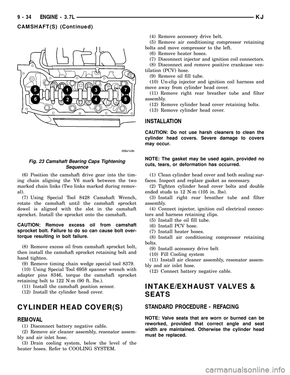
(6) Position the camshaft drive gear into the tim-
ing chain aligning the V6 mark between the two
marked chain links (Two links marked during remov-
al).
(7) Using Special Tool 8428 Camshaft Wrench,
rotate the camshaft until the camshaft sprocket
dowel is aligned with the slot in the camshaft
sprocket. Install the sprocket onto the camshaft.
CAUTION: Remove excess oil from camshaft
sprocket bolt. Failure to do so can cause bolt over-
torque resulting in bolt failure.
(8) Remove excess oil from camshaft sprocket bolt,
then install the camshaft sprocket retaining bolt and
hand tighten.
(9) Remove timing chain wedge special tool 8379.
(10) Using Special Tool 6958 spanner wrench with
adapter pins 8346, torque the camshaft sprocket
retaining bolt to 122 N´m (90 ft. lbs.).
(11) Install the camshaft position sensor.
(12) Install the cylinder head cover.
CYLINDER HEAD COVER(S)
REMOVAL
(1) Disconnect battery negative cable.
(2) Remove air cleaner assembly, resonator assem-
bly and air inlet hose.
(3) Drain cooling system, below the level of the
heater hoses. Refer to COOLING SYSTEM.(4) Remove accessory drive belt.
(5) Remove air conditioning compressor retaining
bolts and move compressor to the left.
(6) Remove heater hoses.
(7) Disconnect injector and ignition coil connectors.
(8) Disconnect and remove positive crankcase ven-
tilation (PCV) hose.
(9) Remove oil fill tube.
(10) Un-clip injector and ignition coil harness and
move away from cylinder head cover.
(11) Remove right rear breather tube and filter
assembly.
(12) Remove cylinder head cover retaining bolts.
(13) Remove cylinder head cover.
INSTALLATION
CAUTION: Do not use harsh cleaners to clean the
cylinder head covers. Severe damage to covers
may occur.
NOTE: The gasket may be used again, provided no
cuts, tears, or deformation has occurred.
(1) Clean cylinder head cover and both sealing sur-
faces. Inspect and replace gasket as necessary.
(2) Tighten cylinder head cover bolts and double
ended studs to 12 N´m (105 in. lbs).
(3) Install right rear breather tube and filter
assembly.
(4) Connect injector, ignition coil electrical connec-
tors and harness retaining clips.
(5) Install the oil fill tube.
(6) Install PCV hose.
(7) Install heater hoses.
(8) Install air conditioning compressor retaining
bolts.
(9) Install accessory drive belt
(10) Fill Cooling system
(11) Install air cleaner assembly, resonator assem-
bly and air inlet hose.
(12) Connect battery negative cable.
INTAKE/EXHAUST VALVES &
SEATS
STANDARD PROCEDURE - REFACING
NOTE: Valve seats that are worn or burned can be
reworked, provided that correct angle and seat
width are maintained. Otherwise the cylinder head
must be replaced.
Fig. 23 Camshaft Bearing Caps Tightening
Sequence
9 - 34 ENGINE - 3.7LKJ
CAMSHAFT(S) (Continued)
Page 1284 of 1803
(11) Bleed fuel system. Refer to FUEL SYSTEM.
(12) Remove fuel rail.
(13) Remove throttle body assembly and mounting
bracket.
(14) Drain cooling system below coolant tempera-
ture level. Refer to COOLING SYSTEM.
(15) Remove the heater hoses from the engine
front cover and the heater core.
(16) Unclip and remove heater hoses and tubes
from intake manifold.
(17) Remove coolant temperature sensor. Refer to
FUEL SYSTEM.
(18) Remove intake manifold retaining fasteners in
reverse order of tightening sequence.
(19) Remove intake manifold.
INSTALLATION
(1) Install intake manifold gaskets.
(2) Install intake manifold.
(3) Install intake manifold retaining bolts and
tighten in sequence shown in to 12 N´m (105 in. lbs.).
(4) Install left and right radio suppressor straps.
(5) Install throttle body assembly.
(6) Install throttle cable bracket.
(7) Connect throttle cable and speed control cable
to throttle body.
(8) Install fuel rail.
(9) Install ignition coil towers.
(10) Position and install heater hoses and tubes
onto intake manifold.
(11) Install the heater hoses to the heater core and
engine front cover.
(12) Connect electrical connectors for the following
components:
²Manifold Absolute Pressure (MAP) Sensor
²Intake Air Temperature (IAT) Sensor
²Throttle Position (TPS) Sensor
²Coolant Temperature (CTS) Sensor
²Idle Air Control (IAC) Motor
²Ignition coil towers
²Fuel injectors
(13) Install top oil dipstick tube retaining bolt and
ground strap.
(14) Connect generator electrical connections.
(15) Connect Vapor purge hose, Brake booster
hose, Speed control servo hose, Positive crankcase
ventilation (PCV) hose.
(16) Fill cooling system.
(17) Install resonator assembly and air inlet hose.
(18) Connect negative cable to battery.
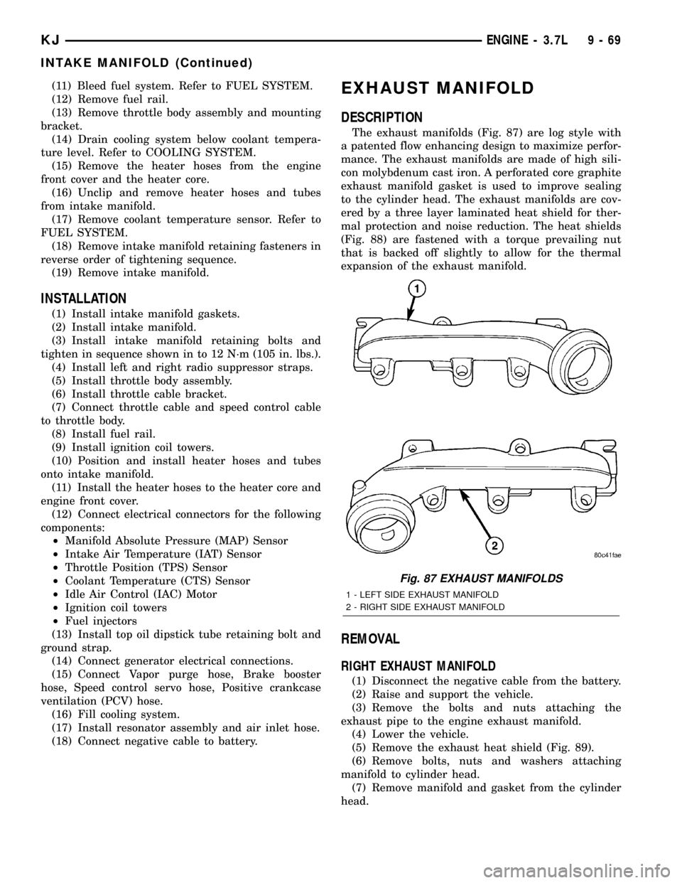
EXHAUST MANIFOLD
DESCRIPTION
The exhaust manifolds (Fig. 87) are log style with
a patented flow enhancing design to maximize perfor-
mance. The exhaust manifolds are made of high sili-
con molybdenum cast iron. A perforated core graphite
exhaust manifold gasket is used to improve sealing
to the cylinder head. The exhaust manifolds are cov-
ered by a three layer laminated heat shield for ther-
mal protection and noise reduction. The heat shields
(Fig. 88) are fastened with a torque prevailing nut
that is backed off slightly to allow for the thermal
expansion of the exhaust manifold.
REMOVAL
RIGHT EXHAUST MANIFOLD
(1) Disconnect the negative cable from the battery.
(2) Raise and support the vehicle.
(3) Remove the bolts and nuts attaching the
exhaust pipe to the engine exhaust manifold.
(4) Lower the vehicle.
(5) Remove the exhaust heat shield (Fig. 89).
(6) Remove bolts, nuts and washers attaching
manifold to cylinder head.
(7) Remove manifold and gasket from the cylinder
head.
Fig. 87 EXHAUST MANIFOLDS
1 - LEFT SIDE EXHAUST MANIFOLD
2 - RIGHT SIDE EXHAUST MANIFOLD
KJENGINE - 3.7L 9 - 69
INTAKE MANIFOLD (Continued)
Page 1303 of 1803
CONDITION POSSIBLE CAUSE CORRECTION
ENGINE STALLS OR IDLES
ROUGH1. Idle speed too low. 1. Test minimum air flow. (Refer to
Appropriate Diagnostic Information)
2. Incorrect fuel mixture. 2. (Refer to Appropriate Diagnostic
Information)
3. Intake manifold leakage. 3. Inspect intake manifold, manifold
gasket, and vacuum hoses.
4. Faulty ignition coil(s). 4. Test and replace as necessary.
(Refer to Appropriate Diagnostic
Information)
ENGINE LOSS OF POWER 1. Dirty or incorrectly gapped plugs. 1. Clean plugs and set gap.
2. Contamination in fuel system. 2. Clean system and replace fuel
filter.
3. Faulty fuel pump. 3. Test and replace as necessary.
(Refer to Appropriate Diagnostic
Information)
4. Incorrect valve timing. 4. Correct valve timing.
5. Leaking cylinder head gasket. 5. Replace cylinder head gasket.
6. Low compression. 6. Test compression of each
cylinder.
7. Burned, warped, or pitted valves. 7. Replace valves.
8. Plugged or restricted exhaust
system.8. Perform exhaust restriction test.
(Refer to 11 - EXHAUST SYSTEM -
DIAGNOSIS AND TESTING) Install
new parts, as necessary.
9. Faulty ignition coil(s). 9. Test and replace as necessary.
(Refer to Appropriate Diagnostic
Information)
ENGINE MISSES ON
ACCELERATION1. Dirty or incorrectly gapped spark
plugs.1. Clean spark plugs and set gap.
2. Contamination in Fuel System. 2. Clean fuel system and replace
fuel filter.
3. Burned, warped, or pitted valves. 3. Replace valves.
4. Faulty ignition coil(s). 4. Test and replace as necessary.
(Refer to Appropriate Diagnostic
Information)
ENGINE MISSES AT HIGH SPEED 1. Dirty or incorrect spark plug gap. 1. Clean spark plugs and set gap.
2. Faulty ignition coil(s). 2. Test and replace as necessary.
(Refer to Appropriate Diagnostic
Information)
3. Dirty fuel injector(s). Test and replace as necessary.
(Refer to Appropriate Diagnostic
Information)
4. Contamination in fuel system. 4. Clean system and replace fuel
filter.
9s - 6 ENGINEKJ
ENGINE - 2.4L (Continued)
Page 1309 of 1803
NOTE: Plastigage is available in a variety of clear-
ance ranges. Use the most appropriate range for
the specifications you are checking.
(4) Install the proper crankshaft bearings to
achieve the specified bearing clearances. (Refer to 9 -
ENGINE/ENGINE BLOCK/CRANKSHAFT MAIN
BEARINGS - STANDARD PROCEDURE) (Refer to 9
- ENGINE/ENGINE BLOCK/CONNECTING ROD
BEARINGS - STANDARD PROCEDURE)
REMOVAL - ENGINE ASSEMBLY
(1) Disconnect the battery negative cable.
(2) Remove hood. Mark hood hinge location for
reinstallation.
(3) Remove air cleaner assembly.
(4) Remove radiator core support bracket.
(5) Remove fan shroud with electric fan assembly.
(6) Remove drive belt.
NOTE: It is NOT necessary to discharge the A/C
system to remove the engine.
(7) Remove A/C compressor and secure away from
engine with lines attached.
(8) Remove generator and secure away from
engine.
NOTE: Do NOT remove the phenolic pulley from the
P/S pump. It is not required for P/S pump removal.
(9) Remove power steering pump with lines
attached and secure away from engine.
(10) Drain cooling system.
(11) Remove coolant bottle.
(12) Disconnect the heater hoses from the engine.
(13) Disconnect heater hoses from heater core and
remove hose assembly.
(14) Disconnect throttle and speed control cables.
(15) Remove upper radiator hose from engine.
(16) Remove lower radiator hose from engine.
(17) Disconnect the engine to body ground straps
at the left side of cowl.
(18) Disconnect the engine wiring harness at the
following points:
²Intake air temperature (IAT) sensor
²Fuel Injectors
²Throttle Position (TPS) Switch
²Idle Air Control (IAC) Motor
²Engine Oil Pressure Switch
²Engine Coolant Temperature (ECT) Sensor
²Manifold Absolute Pressure MAP) Sensor
²Camshaft Position (CMP) Sensor
²Coil Over Plugs
²Crankshaft Position Sensor
(19) Remove coil over plugs.
(20) Release fuel rail pressure.(21) Remove fuel rail and secure away from
engine.
(22) Remove the PCV hose.
(23) Remove the breather hoses.
(24) Remove the vacuum hose for the power brake
booster.
(25) Disconnect knock sensors.
(26) Secure the left and right engine wiring har-
nesses away from engine.
(27) Raise vehicle.
(28) Disconnect oxygen sensor wiring.
(29) Disconnect crankshaft postion sensor.
(30) Disconnect the engine block heater power
cable, if equipped.
(31) Disconnect the front propshaft at the front
differential and secure out of way.
(32) Remove the starter.
(33) Remove the ground straps from the engine
(34) Disconnect the exhaust pipes at the manifold.
(35) Remove the structural cover, if equipped.
(36) Remove torque convertor bolts, and mark
location for reassembly.
(37) Remove transmission bellhousing to engine
bolts.
(38) Loosen left and right engine mount thru bolts.
NOTE: It is not necessary to completely remove
engine mount thru bolts, for engine removal.
(39) Lower the vehicle.
(40) Support the transmission with a suitable jack.
(41) Connect a suitable engine hoist to the engine.
CAUTION: The 2.4L engine with manual transmis-
sions, can be removed without removing the man-
ual transmission. Use caution when attempting this
procedure as the clearance is tight.
(42) Remove engine from vehicle.
INSTALLATION - ENGINE ASSEMBLY
(1) Position the engine in the vehicle.
CAUTION: Use caution when installing 2.4L engine
into vehicle equipped with manual transmission, as
clearance is tight.
(2) Install both left and right side engine mounts
into the frame mounts.
(3) Raise the vehicle.
(4) Install the transmission bellhousing to engine
mounting bolts. Tighten the bolts to 41 N´m (30ft.
lbs.).
(5) Tighten the engine mount thru bolts.
(6) Install the torque convertor bolts.
(7) Connect the ground straps on the left and right
side of the engine.
9s - 12 ENGINEKJ
ENGINE - 2.4L (Continued)