2002 JEEP LIBERTY change time
[x] Cancel search: change timePage 718 of 1803

WASHER FLUID LEVEL
SWITCH
DESCRIPTION
The washer fluid level switch is a single pole, sin-
gle throw reed-type switch mounted at the rear of
the sump area near the bottom of the washer reser-
voir (Fig. 16). Only the molded plastic switch mount-
ing flange and the integral connector receptacle are
visible when the switch is installed in the reservoir.
A short nipple formation extends from the inner sur-
face of the switch mounting flange, and a barb on the
nipple near the switch mounting flange is pressed
through a rubber grommet seal installed in the
mounting hole of the reservoir. A small, molded plas-
tic float has two pivot pins near its center that are
snapped into two receptacles near the ends of two
stanchions that extend toward the float from the
switch nipple formation. A small magnet is secured
within the end of the float nearest the switch nipple
formation, and a reed switch is concealed within the
nipple. A diagnostic resistor is connected between the
two switch terminals within the switch mounting
flange. The washer fluid level switch cannot be
adjusted or repaired. If faulty or damaged, the switch
must be replaced.
OPERATION
The washer fluid level switch uses a pivoting,
oblong float to monitor the level of the washer fluid
in the washer reservoir. The float contains a small
magnet. When the float pivots, the proximity of this
magnet to a stationary reed switch within the nipple
formation of the switch changes. When the fluid level
in the washer reservoir is at or above the float level,
the float moves to a vertical position, the influence of
the float magnetic field is removed from the reed
switch, and the normally open reed switch contacts
open. When the fluid level in the washer reservoir
falls below the level of the pivoting float, the float
moves to a horizontal position, the influence of the
float magnetic field is applied to the reed switch, and
the contacts of the normally open reed switch close.
The washer fluid level switch is connected to the
vehicle electrical system through a dedicated take
out and connector of the headlamp and dash wire
harness. The switch is connected in series between
ground and the washer fluid switch sense input to
the ElectroMechanical Instrument Cluster (EMIC).
The switch receives a path to ground at all times
through another take out of the headlamp and dash
wire harness with a single eyelet terminal connector
that is secured under a ground screw near the front
of the left front fender inner shield in the engine
compartment. When the switch closes, the EMIC
senses the ground on the washer fluid switch sense
circuit. The EMIC is programmed to respond to this
input by illuminating the washer fluid indicator and
by sounding an audible chime tone warning.
The washer fluid level switch input to the EMIC
can be diagnosed using conventional diagnostic tools
and methods. (Refer to 8 - ELECTRICAL/INSTRU-
MENT CLUSTER/WASHER FLUID INDICATOR -
DIAGNOSIS AND TESTING).
REMOVAL
The washer fluid level switch can be removed from
the washer reservoir without removing the reservoir
from the vehicle.
(1) Disconnect and isolate the battery negative
cable.
(2) Raise and support the vehicle.
(3) Remove the splash shield from the right front
fender wheel house. (Refer to 23 - BODY/EXTERIOR/
FRONT WHEELHOUSE SPLASH SHIELD -
REMOVAL).
(4) Disconnect the front or rear washer hose from
one of the barbed outlet nipples of the washer pump/
motor unit and allow the washer fluid to drain into a
clean container for reuse.
(5) Disconnect the headlamp and dash wire har-
ness connector for the washer fluid level switch from
the switch connector receptacle (Fig. 17).
Fig. 16 Washer Fluid Level Switch
1 - MOUNTING FLANGE
2 - BARBED NIPPLE
3 - FLOAT
4 - RESERVOIR
5 - GROMMET SEAL
6 - PIVOT
7 - MAGNET
8 - CONNECTOR RECEPTACLE
KJFRONT WIPERS/WASHERS 8R - 17
Page 741 of 1803
and maintain proper contact with the glass, even as
the blade is moved over the varied curvature found
across the glass surface. The wiper element flexor
provides the claws of the blade superstructure with a
rigid, yet flexible component on the element which
can be gripped. The rubber element is designed to be
stiff enough to maintain an even cleaning edge as it
is drawn across the glass, but resilient enough to
conform to the glass surface and flip from one clean-
ing edge to the other each time the wiper blade
changes directions.
REMOVAL
NOTE: The notched end of the wiper element flexor
should always be oriented towards the end of the
wiper blade that is nearest to the wiper motor out-
put shaft.
(1) Disengage the rear wiper arm support from the
rear wiper arm park ramp on the right side of the
tailgate just below the rear flip-up glass.
(2) Lift the rear wiper arm to raise the wiper blade
and element off of the tailgate and the rear flip-up
glass.
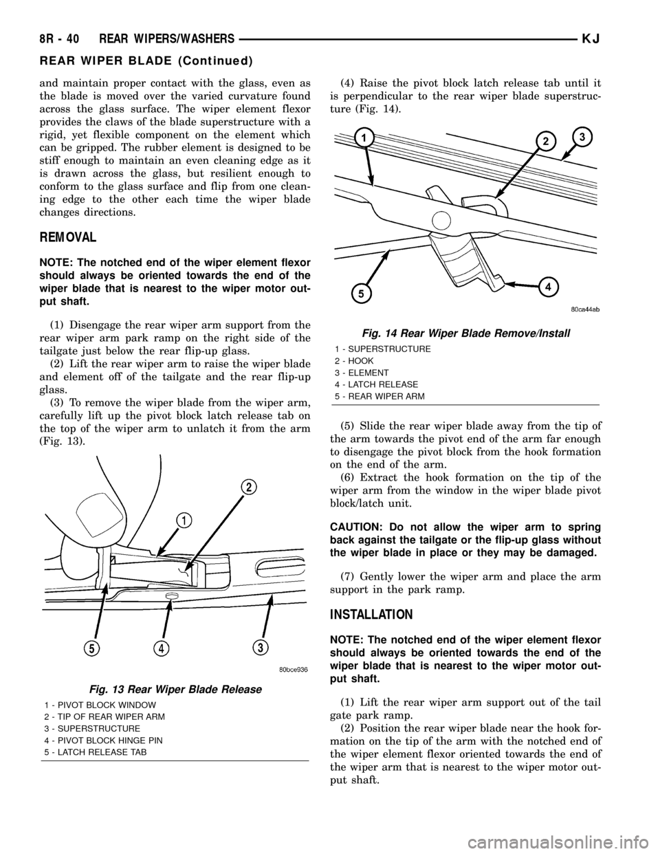
(3) To remove the wiper blade from the wiper arm,
carefully lift up the pivot block latch release tab on
the top of the wiper arm to unlatch it from the arm
(Fig. 13).(4) Raise the pivot block latch release tab until it
is perpendicular to the rear wiper blade superstruc-
ture (Fig. 14).
(5) Slide the rear wiper blade away from the tip of
the arm towards the pivot end of the arm far enough
to disengage the pivot block from the hook formation
on the end of the arm.
(6) Extract the hook formation on the tip of the
wiper arm from the window in the wiper blade pivot
block/latch unit.
CAUTION: Do not allow the wiper arm to spring
back against the tailgate or the flip-up glass without
the wiper blade in place or they may be damaged.
(7) Gently lower the wiper arm and place the arm
support in the park ramp.
INSTALLATION
NOTE: The notched end of the wiper element flexor
should always be oriented towards the end of the
wiper blade that is nearest to the wiper motor out-
put shaft.
(1) Lift the rear wiper arm support out of the tail
gate park ramp.
(2) Position the rear wiper blade near the hook for-
mation on the tip of the arm with the notched end of
the wiper element flexor oriented towards the end of
the wiper arm that is nearest to the wiper motor out-
put shaft.
Fig. 13 Rear Wiper Blade Release
1 - PIVOT BLOCK WINDOW
2 - TIP OF REAR WIPER ARM
3 - SUPERSTRUCTURE
4 - PIVOT BLOCK HINGE PIN
5 - LATCH RELEASE TAB
Fig. 14 Rear Wiper Blade Remove/Install
1 - SUPERSTRUCTURE
2 - HOOK
3 - ELEMENT
4 - LATCH RELEASE
5 - REAR WIPER ARM
8R - 40 REAR WIPERS/WASHERSKJ
REAR WIPER BLADE (Continued)
Page 762 of 1803

8W-02 COMPONENT INDEX
Component Page
A/C Compressor Clutch Relay........... 8Wa-42
A/C Compressor Clutch................ 8Wa-42
A/C-Heater Control................... 8Wa-42
A/C High Pressure Switch.............. 8Wa-42
A/C Low Pressure Switch............... 8Wa-42
A/C Pressure Transducer............... 8Wa-42
Accelerator Pedal Position Sensor........ 8Wa-30
Airbag Control Module................. 8Wa-43
Ambient Temperature Sensor............ 8Wa-45
Antenna Module...................... 8Wa-47
Antenna............................ 8Wa-47
Ash Receiver Lamp................... 8Wa-44
Auto Shut Down Relay................. 8Wa-30
Back-Up Lamp Switch................. 8Wa-31
Battery Temperature Sensor......... 8Wa-20, 30
Battery............................. 8Wa-20
Blend Door Actuator................... 8Wa-42
Blower Motor Relay................... 8Wa-42
Blower Motor Resistor Block............ 8Wa-42
Blower Motor........................ 8Wa-42
Body Control Module.................. 8Wa-45
Boost Pressure Sensor................. 8Wa-30
Brake Lamp Switch................... 8Wa-33
Brake Pressure Switch................. 8Wa-35
Cabin Heater Relay................... 8Wa-42
Cabin Heater........................ 8Wa-42
Camshaft Position Sensor.............. 8Wa-30
Capacitor........................... 8Wa-30
Cargo Lamp......................... 8Wa-44
CD Changer......................... 8Wa-47
Center High Mounted Stop Lamp........ 8Wa-51
Cigar Lighter........................ 8Wa-41
Circuit Breakers...................... 8Wa-12
Clockspring................. 8Wa-33, 41, 43, 47
Clutch Interlock Switch................ 8Wa-21
Clutch Switch Override Relay........... 8Wa-21
Coil On Plugs........................ 8Wa-30
Coil Rail............................ 8Wa-30
Compass Mini-Trip Computer........... 8Wa-49
Controller Antilock Brake.............. 8Wa-35
Courtesy Lamps...................... 8Wa-44
Crankshaft Position Sensor............. 8Wa-30
Curtain Airbags...................... 8Wa-43
Cylinder Lock Switches................ 8Wa-61
Data Link Connector.................. 8Wa-18
Daytime Running Lamp Relay........... 8Wa-50
Defogger Relay....................... 8Wa-48
Diagnostic Junction Port............... 8Wa-18
Dome Lamp......................... 8Wa-44
Door Ajar Switches.................... 8Wa-45
Door Lock Motor/Ajar Switches.......... 8Wa-61
Door Lock Relay...................... 8Wa-61Component Page
Door Lock Switches................... 8Wa-61
Door Speakers....................... 8Wa-47
Driver Airbag Squib 1................. 8Wa-43
Driver Airbag Squib 2................. 8Wa-43
Driver Door Unlock Relay.............. 8Wa-61
Driver Seat Belt Switch................ 8Wa-40
Driver Seat Belt Tensioner.............. 8Wa-43
EGR Solenoid........................ 8Wa-30
Electric Brake Provision................ 8Wa-54
Engine Control Module................ 8Wa-30
Engine Coolant Level Sensor............ 8Wa-40
Engine Coolant Temperature Sensor...... 8Wa-30
Engine Oil Pressure Sensor............. 8Wa-30
EVAP/Purge Solenoid.................. 8Wa-30
Flip-Up Glass Release Motor............ 8Wa-61
Flip-Up Glass Release Switch........... 8Wa-61
Fog Lamps.......................... 8Wa-50
Front Fog Lamp Relay................. 8Wa-50
Front Wiper Motor.................... 8Wa-53
Fuel Heater Relay.................... 8Wa-30
Fuel Heater......................... 8Wa-30
Fuel Injectors........................ 8Wa-30
Fuel Pressure Sensor.................. 8Wa-30
Fuel Pressure Solenoid................. 8Wa-30
Fuel Pump Module.................... 8Wa-30
Fuel Pump Relay..................... 8Wa-30
Fuses........................... 8Wa-10, 12
Fusible Link......................... 8Wa-20
Grounds............................ 8Wa-15
Generator........................... 8Wa-20
Glow Plugs.......................... 8Wa-30
Hazard Switch/Combination Flasher...... 8Wa-52
Headlamp Leveling Switch.............. 8Wa-50
Headlamps.......................... 8Wa-50
Heated Seats........................ 8Wa-63
High Beam Relay..................... 8Wa-50
Horns.............................. 8Wa-41
Hood Ajar Switch..................... 8Wa-45
Idle Air Control Motor................. 8Wa-30
Ignition Switch....................... 8Wa-10
Impact Sensors....................... 8Wa-43
Input Speed Sensor................... 8Wa-31
Instrument Cluster................... 8Wa-40
Instrument Panel Speakers............. 8Wa-47
Intake Air Temperature Sensor.......... 8Wa-30
Intrusion Sensor..................... 8Wa-49
Junction Block....................... 8Wa-12
Knock Sensor........................ 8Wa-30
Leak Detection Pump.................. 8Wa-30
Leveling Motors...................... 8Wa-50
License Lamp........................ 8Wa-51
Line Pressure Sensor.................. 8Wa-31
KJ8W-02 COMPONENT INDEX8Wa-02-1
Page 1221 of 1803
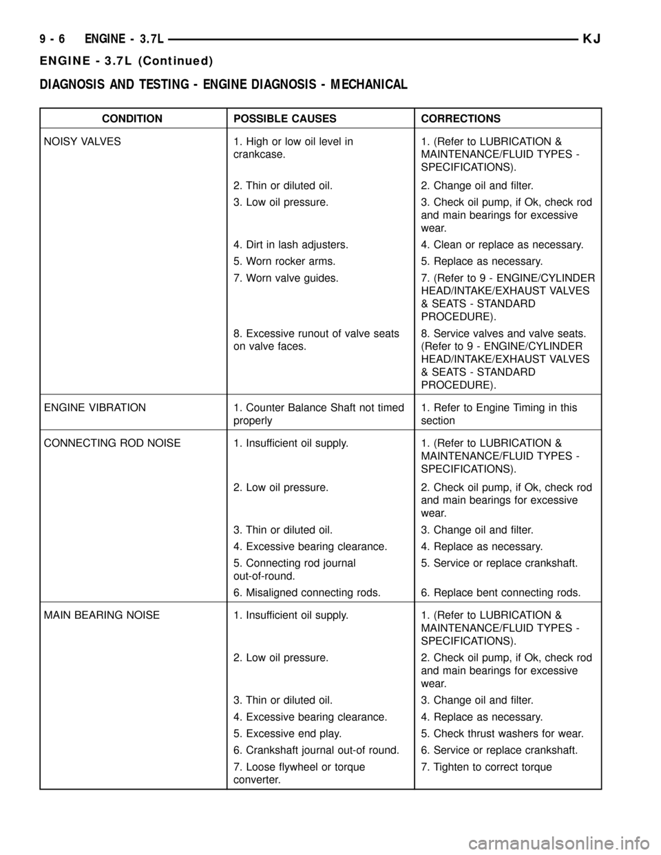
DIAGNOSIS AND TESTING - ENGINE DIAGNOSIS - MECHANICAL
CONDITION POSSIBLE CAUSES CORRECTIONS
NOISY VALVES 1. High or low oil level in
crankcase.1. (Refer to LUBRICATION &
MAINTENANCE/FLUID TYPES -
SPECIFICATIONS).
2. Thin or diluted oil. 2. Change oil and filter.
3. Low oil pressure. 3. Check oil pump, if Ok, check rod
and main bearings for excessive
wear.
4. Dirt in lash adjusters. 4. Clean or replace as necessary.
5. Worn rocker arms. 5. Replace as necessary.
7. Worn valve guides. 7. (Refer to 9 - ENGINE/CYLINDER
HEAD/INTAKE/EXHAUST VALVES
& SEATS - STANDARD
PROCEDURE).
8. Excessive runout of valve seats
on valve faces.8. Service valves and valve seats.
(Refer to 9 - ENGINE/CYLINDER
HEAD/INTAKE/EXHAUST VALVES
& SEATS - STANDARD
PROCEDURE).
ENGINE VIBRATION 1. Counter Balance Shaft not timed
properly1. Refer to Engine Timing in this
section
CONNECTING ROD NOISE 1. Insufficient oil supply. 1. (Refer to LUBRICATION &
MAINTENANCE/FLUID TYPES -
SPECIFICATIONS).
2. Low oil pressure. 2. Check oil pump, if Ok, check rod
and main bearings for excessive
wear.
3. Thin or diluted oil. 3. Change oil and filter.
4. Excessive bearing clearance. 4. Replace as necessary.
5. Connecting rod journal
out-of-round.5. Service or replace crankshaft.
6. Misaligned connecting rods. 6. Replace bent connecting rods.
MAIN BEARING NOISE 1. Insufficient oil supply. 1. (Refer to LUBRICATION &
MAINTENANCE/FLUID TYPES -
SPECIFICATIONS).
2. Low oil pressure. 2. Check oil pump, if Ok, check rod
and main bearings for excessive
wear.
3. Thin or diluted oil. 3. Change oil and filter.
4. Excessive bearing clearance. 4. Replace as necessary.
5. Excessive end play. 5. Check thrust washers for wear.
6. Crankshaft journal out-of round. 6. Service or replace crankshaft.
7. Loose flywheel or torque
converter.7. Tighten to correct torque
9 - 6 ENGINE - 3.7LKJ
ENGINE - 3.7L (Continued)
Page 1277 of 1803

ple viscosities such as 5W-30 or 10W-30 in the 3.7L
engines. These are specified with a dual SAE viscos-
ity grade which indicates the cold-to-hot temperature
viscosity range. Select an engine oil that is best
suited to your particular temperature range and vari-
ation (Fig. 71).
ENERGY CONSERVING OIL
An Energy Conserving type oil is recommended for
gasoline engines. The designation of ENERGY CON-
SERVING is located on the label of an engine oil con-
tainer.
CONTAINER IDENTIFICATION
Standard engine oil identification notations have
been adopted to aid in the proper selection of engine
oil. The identifying notations are located on the label
of engine oil plastic bottles and the top of engine oil
cans (Fig. 72).
OIL LEVEL INDICATOR (DIPSTICK)
The engine oil level indicator is located on the
right side of the the 3.7L engine.
CRANKCASE OIL LEVEL INSPECTION
CAUTION: Do not overfill crankcase with engine oil,
pressure loss or oil foaming can result.Inspect engine oil level approximately every 800
kilometers (500 miles). Unless the engine has exhib-
ited loss of oil pressure, run the engine for about five
minutes before checking oil level. Checking engine oil
level on a cold engine is not accurate.
To ensure proper lubrication of an engine, the
engine oil must be maintained at an acceptable level.
The acceptable levels are indicated between the ADD
and SAFE marks on the engine oil dipstick.
(1) Position vehicle on level surface.
(2) With engine OFF, allow approximately ten min-
utes for oil to settle to bottom of crankcase, remove
engine oil dipstick.
(3) Wipe dipstick clean.
(4) Install dipstick and verify it is seated in the
tube.
(5) Remove dipstick, with handle held above the
tip, take oil level reading.
(6) Add oil if level is below the SAFE ZONE on
dipstick.
ENGINE OIL CHANGE
Change engine oil at mileage and time intervals
described in Maintenance Schedules.
Run engine until achieving normal operating tem-
perature.
(1) Position the vehicle on a level surface and turn
engine off.
(2) Remove oil fill cap.
(3) Hoist and support vehicle on safety stands.
(4) Place a suitable drain pan under crankcase
drain.
(5) Remove drain plug from crankcase and allow
oil to drain into pan. Inspect drain plug threads for
stretching or other damage. Replace drain plug if
damaged.
(6) Install drain plug in crankcase.
(7) Remove oil filter (Refer to 9 - ENGINE/LUBRI-
CATION/OIL FILTER - REMOVAL).
(8) Install a new oil filter.
(9) Lower vehicle and fill crankcase with 5 quarts
of the specified type of engine oil described in this
section.
(10) Install oil fill cap.
(11) Start engine and inspect for leaks.
(12) Stop engine and inspect oil level.
USED ENGINE OIL DISPOSAL
Care should be exercised when disposing used
engine oil after it has been drained from a vehicle
engine. Refer to the WARNING at beginning of this
section.
Fig. 71 Temperature/Engine Oil Viscosity - 3.7L
Engine
Fig. 72 Engine Oil Container Standard Notations
9 - 62 ENGINE - 3.7LKJ
OIL (Continued)
Page 1321 of 1803
REMOVAL
(1) Remove cylinder head cover. (Refer to 9 -
ENGINE/CYLINDER HEAD/CYLINDER HEAD
COVER(S) - REMOVAL)
(2) Remove camshaft position sensor and camshaft
target magnet. (Refer to 8 - ELECTRICAL/IGNI-
TION CONTROL/CAMSHAFT POSITION SENSOR -
REMOVAL)
(3) Remove timing belt. (Refer to 9 - ENGINE/
VALVE TIMING/TIMING BELT/CHAIN AND
SPROCKETS - REMOVAL)(4) Remove camshaft sprockets and timing belt
rear cover. (Refer to 9 - ENGINE/VALVE TIMING/
TIMING BELT / CHAIN COVER(S) - REMOVAL)
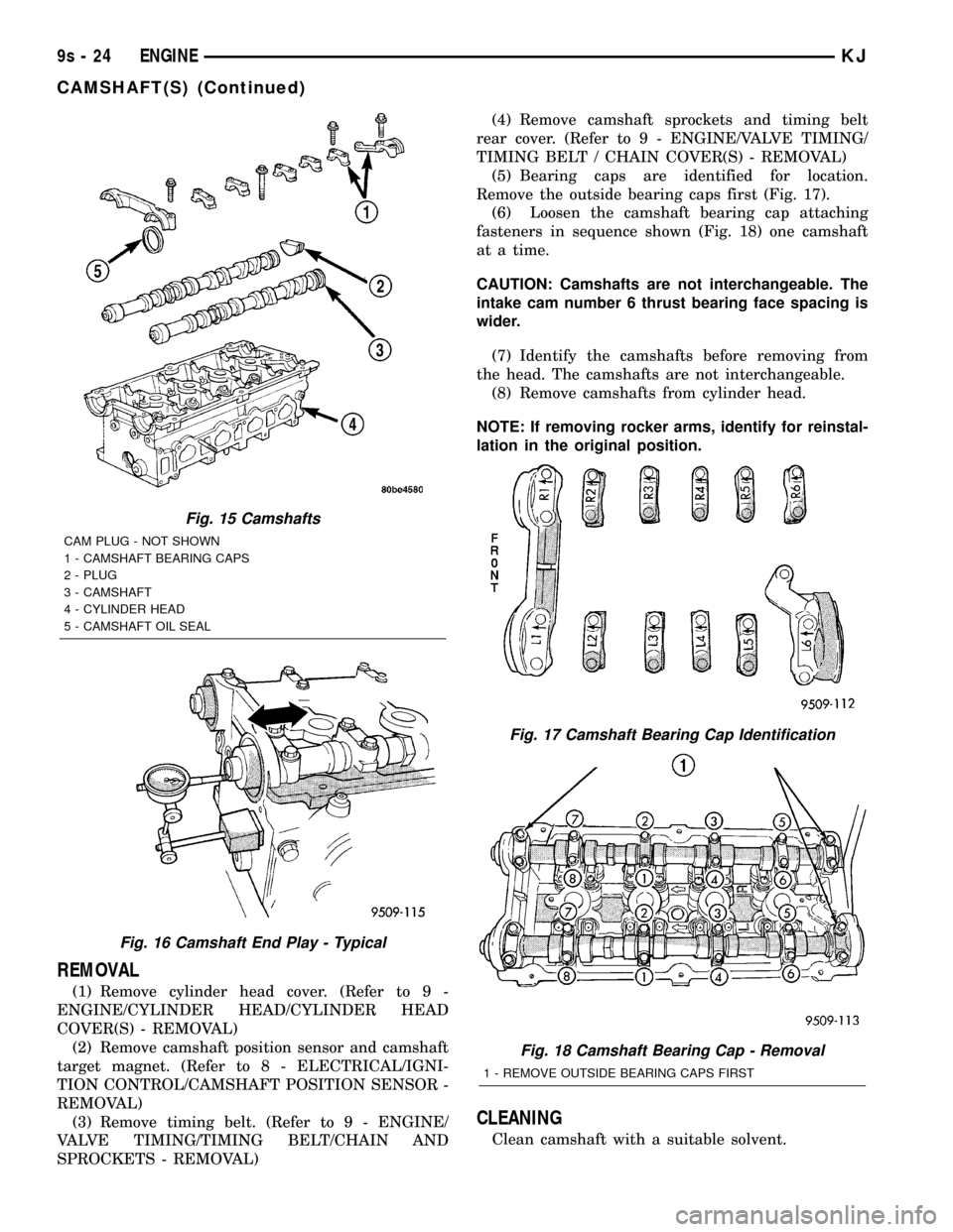
(5) Bearing caps are identified for location.
Remove the outside bearing caps first (Fig. 17).
(6) Loosen the camshaft bearing cap attaching
fasteners in sequence shown (Fig. 18) one camshaft
at a time.
CAUTION: Camshafts are not interchangeable. The
intake cam number 6 thrust bearing face spacing is
wider.
(7) Identify the camshafts before removing from
the head. The camshafts are not interchangeable.
(8) Remove camshafts from cylinder head.
NOTE: If removing rocker arms, identify for reinstal-
lation in the original position.
CLEANING
Clean camshaft with a suitable solvent.
Fig. 15 Camshafts
CAM PLUG - NOT SHOWN
1 - CAMSHAFT BEARING CAPS
2 - PLUG
3 - CAMSHAFT
4 - CYLINDER HEAD
5 - CAMSHAFT OIL SEAL
Fig. 16 Camshaft End Play - Typical
Fig. 17 Camshaft Bearing Cap Identification
Fig. 18 Camshaft Bearing Cap - Removal
1 - REMOVE OUTSIDE BEARING CAPS FIRST
9s - 24 ENGINEKJ
CAMSHAFT(S) (Continued)
Page 1338 of 1803
INSTALLATION
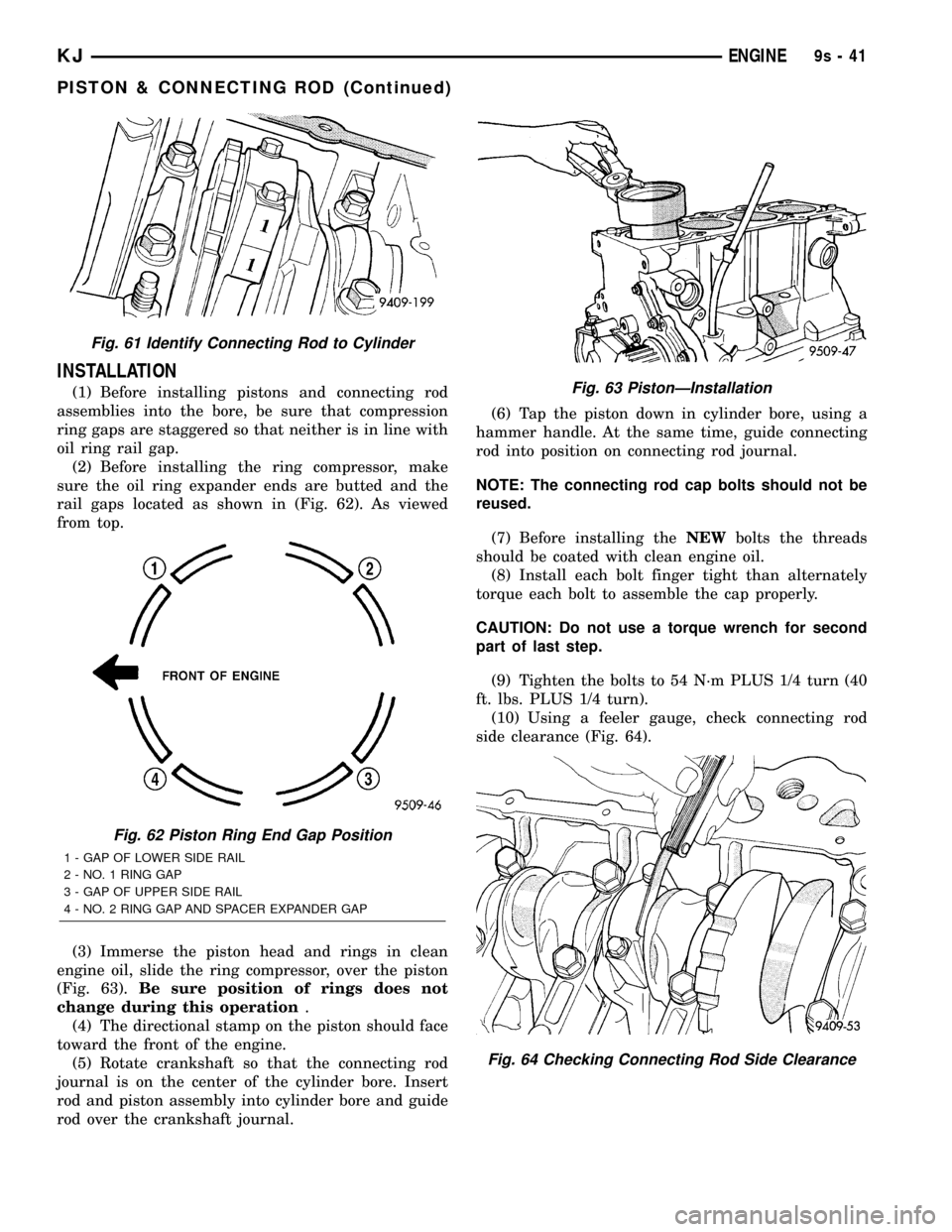
(1) Before installing pistons and connecting rod
assemblies into the bore, be sure that compression
ring gaps are staggered so that neither is in line with
oil ring rail gap.
(2) Before installing the ring compressor, make
sure the oil ring expander ends are butted and the
rail gaps located as shown in (Fig. 62). As viewed
from top.
(3) Immerse the piston head and rings in clean
engine oil, slide the ring compressor, over the piston
(Fig. 63).Be sure position of rings does not
change during this operation.
(4) The directional stamp on the piston should face
toward the front of the engine.
(5) Rotate crankshaft so that the connecting rod
journal is on the center of the cylinder bore. Insert
rod and piston assembly into cylinder bore and guide
rod over the crankshaft journal.(6) Tap the piston down in cylinder bore, using a
hammer handle. At the same time, guide connecting
rod into position on connecting rod journal.
NOTE: The connecting rod cap bolts should not be
reused.
(7) Before installing theNEWbolts the threads
should be coated with clean engine oil.
(8) Install each bolt finger tight than alternately
torque each bolt to assemble the cap properly.
CAUTION: Do not use a torque wrench for second
part of last step.
(9) Tighten the bolts to 54 N´m PLUS 1/4 turn (40
ft. lbs. PLUS 1/4 turn).
(10) Using a feeler gauge, check connecting rod
side clearance (Fig. 64).
Fig. 61 Identify Connecting Rod to Cylinder
Fig. 62 Piston Ring End Gap Position
1 - GAP OF LOWER SIDE RAIL
2 - NO. 1 RING GAP
3 - GAP OF UPPER SIDE RAIL
4 - NO. 2 RING GAP AND SPACER EXPANDER GAP
Fig. 63 PistonÐInstallation
Fig. 64 Checking Connecting Rod Side Clearance
KJENGINE9s-41
PISTON & CONNECTING ROD (Continued)
Page 1344 of 1803
(6) Install oil pressure switch and connector. (Refer
to 9 - ENGINE/LUBRICATION/OIL PRESSURE
SENSOR/SWITCH - INSTALLATION)
OIL
STANDARD PROCEDURE
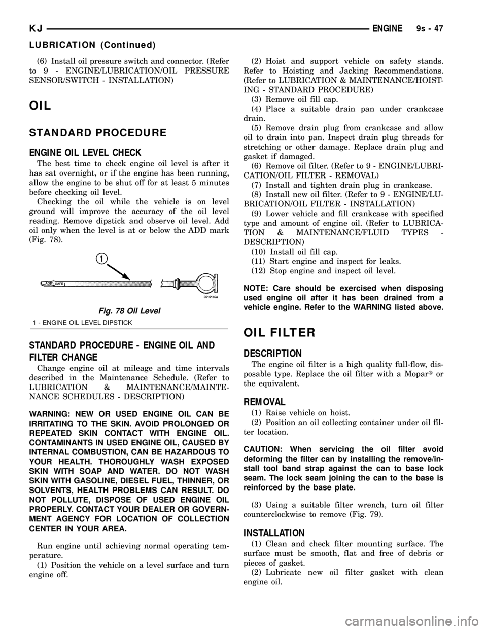
ENGINE OIL LEVEL CHECK
The best time to check engine oil level is after it
has sat overnight, or if the engine has been running,
allow the engine to be shut off for at least 5 minutes
before checking oil level.
Checking the oil while the vehicle is on level
ground will improve the accuracy of the oil level
reading. Remove dipstick and observe oil level. Add
oil only when the level is at or below the ADD mark
(Fig. 78).
STANDARD PROCEDURE - ENGINE OIL AND
FILTER CHANGE
Change engine oil at mileage and time intervals
described in the Maintenance Schedule. (Refer to
LUBRICATION & MAINTENANCE/MAINTE-
NANCE SCHEDULES - DESCRIPTION)
WARNING: NEW OR USED ENGINE OIL CAN BE
IRRITATING TO THE SKIN. AVOID PROLONGED OR
REPEATED SKIN CONTACT WITH ENGINE OIL.
CONTAMINANTS IN USED ENGINE OIL, CAUSED BY
INTERNAL COMBUSTION, CAN BE HAZARDOUS TO
YOUR HEALTH. THOROUGHLY WASH EXPOSED
SKIN WITH SOAP AND WATER. DO NOT WASH
SKIN WITH GASOLINE, DIESEL FUEL, THINNER, OR
SOLVENTS, HEALTH PROBLEMS CAN RESULT. DO
NOT POLLUTE, DISPOSE OF USED ENGINE OIL
PROPERLY. CONTACT YOUR DEALER OR GOVERN-
MENT AGENCY FOR LOCATION OF COLLECTION
CENTER IN YOUR AREA.
Run engine until achieving normal operating tem-
perature.
(1) Position the vehicle on a level surface and turn
engine off.(2) Hoist and support vehicle on safety stands.
Refer to Hoisting and Jacking Recommendations.
(Refer to LUBRICATION & MAINTENANCE/HOIST-
ING - STANDARD PROCEDURE)
(3) Remove oil fill cap.
(4) Place a suitable drain pan under crankcase
drain.
(5) Remove drain plug from crankcase and allow
oil to drain into pan. Inspect drain plug threads for
stretching or other damage. Replace drain plug and
gasket if damaged.
(6) Remove oil filter. (Refer to 9 - ENGINE/LUBRI-
CATION/OIL FILTER - REMOVAL)
(7) Install and tighten drain plug in crankcase.
(8) Install new oil filter. (Refer to 9 - ENGINE/LU-
BRICATION/OIL FILTER - INSTALLATION)
(9) Lower vehicle and fill crankcase with specified
type and amount of engine oil. (Refer to LUBRICA-
TION & MAINTENANCE/FLUID TYPES -
DESCRIPTION)
(10) Install oil fill cap.
(11) Start engine and inspect for leaks.
(12) Stop engine and inspect oil level.
NOTE: Care should be exercised when disposing
used engine oil after it has been drained from a
vehicle engine. Refer to the WARNING listed above.
OIL FILTER
DESCRIPTION
The engine oil filter is a high quality full-flow, dis-
posable type. Replace the oil filter with a Mopartor
the equivalent.
REMOVAL
(1) Raise vehicle on hoist.
(2) Position an oil collecting container under oil fil-
ter location.
CAUTION: When servicing the oil filter avoid
deforming the filter can by installing the remove/in-
stall tool band strap against the can to base lock
seam. The lock seam joining the can to the base is
reinforced by the base plate.
(3) Using a suitable filter wrench, turn oil filter
counterclockwise to remove (Fig. 79).
INSTALLATION
(1) Clean and check filter mounting surface. The
surface must be smooth, flat and free of debris or
pieces of gasket.
(2) Lubricate new oil filter gasket with clean
engine oil.
Fig. 78 Oil Level
1 - ENGINE OIL LEVEL DIPSTICK
KJENGINE9s-47
LUBRICATION (Continued)