2002 JEEP LIBERTY light
[x] Cancel search: lightPage 1430 of 1803

3.7L
The Throttle Position Sensor (TPS) is mounted to
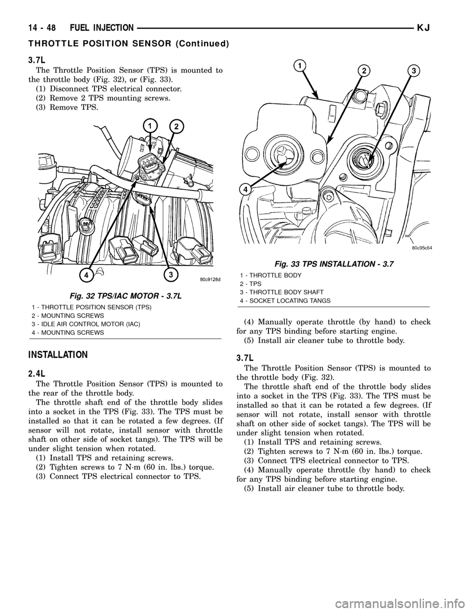
the throttle body (Fig. 32), or (Fig. 33).
(1) Disconnect TPS electrical connector.
(2) Remove 2 TPS mounting screws.
(3) Remove TPS.
INSTALLATION
2.4L
The Throttle Position Sensor (TPS) is mounted to
the rear of the throttle body.
The throttle shaft end of the throttle body slides
into a socket in the TPS (Fig. 33). The TPS must be
installed so that it can be rotated a few degrees. (If
sensor will not rotate, install sensor with throttle
shaft on other side of socket tangs). The TPS will be
under slight tension when rotated.
(1) Install TPS and retaining screws.
(2) Tighten screws to 7 N´m (60 in. lbs.) torque.
(3) Connect TPS electrical connector to TPS.(4) Manually operate throttle (by hand) to check
for any TPS binding before starting engine.
(5) Install air cleaner tube to throttle body.
3.7L
The Throttle Position Sensor (TPS) is mounted to
the throttle body (Fig. 32).
The throttle shaft end of the throttle body slides
into a socket in the TPS (Fig. 33). The TPS must be
installed so that it can be rotated a few degrees. (If
sensor will not rotate, install sensor with throttle
shaft on other side of socket tangs). The TPS will be
under slight tension when rotated.
(1) Install TPS and retaining screws.
(2) Tighten screws to 7 N´m (60 in. lbs.) torque.
(3) Connect TPS electrical connector to TPS.
(4) Manually operate throttle (by hand) to check
for any TPS binding before starting engine.
(5) Install air cleaner tube to throttle body.
Fig. 32 TPS/IAC MOTOR - 3.7L
1 - THROTTLE POSITION SENSOR (TPS)
2 - MOUNTING SCREWS
3 - IDLE AIR CONTROL MOTOR (IAC)
4 - MOUNTING SCREWS
Fig. 33 TPS INSTALLATION - 3.7
1 - THROTTLE BODY
2 - TPS
3 - THROTTLE BODY SHAFT
4 - SOCKET LOCATING TANGS
14 - 48 FUEL INJECTIONKJ
THROTTLE POSITION SENSOR (Continued)
Page 1448 of 1803

NOTE: Power steering pumps have different pres-
sure rates and are not interchangeable with other
pumps.
STANDARD PROCEDURE - POWER STEERING
PUMP - INITIAL OPERATION
WARNING: THE FLUID LEVEL SHOULD BE
CHECKED WITH ENGINE OFF TO PREVENT INJURY
FROM MOVING COMPONENTS.
CAUTION: Use MOPAR Power Steering Fluid or
equivalent. Do not use automatic transmission fluid
and do not overfill.
Wipe filler cap clean, then check the fluid level.
The dipstick should indicateCOLDwhen the fluid is
at normal ambient temperature.
(1) Fill the pump fluid reservoir to the proper level
and let the fluid settle for at least two minutes.
(2) Raise the front wheels off the ground.
(3) Slowly turn the steering wheel right and left,
lightly contacting the wheel stops at least 20 times.
(4) Check the fluid level add if necessary.
(5) Lower the vehicle, start the engine and turn
the steering wheel slowly from lock to lock.
(6) Stop the engine and check the fluid level and
refill as required.
CAUTION: Do not run a vehicle with foamy fluid for
an extended period. This may cause pump damage.
(7) If the fluid is extremely foamy or milky look-
ing, allow the vehicle to stand a few minutes and
repeat the procedure.
(8) Add fluid if necessary. Repeat the above proce-
dure until the fluid level remains constant after run-
ning the engine.
REMOVAL
REMOVAL - 3.7L
(1) Siphon out as much power steering fluid as
possible.
(2) Remove the radiator cross member (Refer to 23
- BODY/EXTERIOR/RADIATOR CROSSMEMBER -
REMOVAL).
(3) Remove the engine cooling fan (Refer to 7 -
COOLING/ENGINE/RADIATOR FAN - REMOVAL).
(4) Remove the fan shroud
(5) Remove the serpentine drive belt (Refer to 7 -
COOLING/ACCESSORY DRIVE/DRIVE BELTS -
REMOVAL).
(6) Remove the power steering high pressure hose
at the pump.
(7) Remove the return hose at the pump.
(8) Remove the three bolts securing the pump to
the bracket thru the holes in the pulley. (Fig. 3)
(9) Remove the pump from the vehicle.
REMOVAL - 2.4L
CAUTION: On vehicles equipped with the 2.4L, Do
not reuse the old power steering pump pulley it is
not intended for reuse. A new pulley must be
installed if removed.
(1) Siphon out as much power steering fluid as
possible.
(2) Remove the serpentine drive belt.
(3) Remove the power steering high pressure hose
at the pump using care not to remove the flow con-
trol valve.
(4) Remove the return hose at the pump.
Fig. 2 FLUID RESERVOIR - 2.4L
Fig. 3 POWER STEERING PUMP - 3.7L
1 - MOUNTING BOLTS
2 - RESERVOIR
3 - STEEL PULLEY
19 - 18 PUMPKJ
PUMP (Continued)
Page 1462 of 1803

DIAGNOSIS AND TESTING - TREAD WEAR
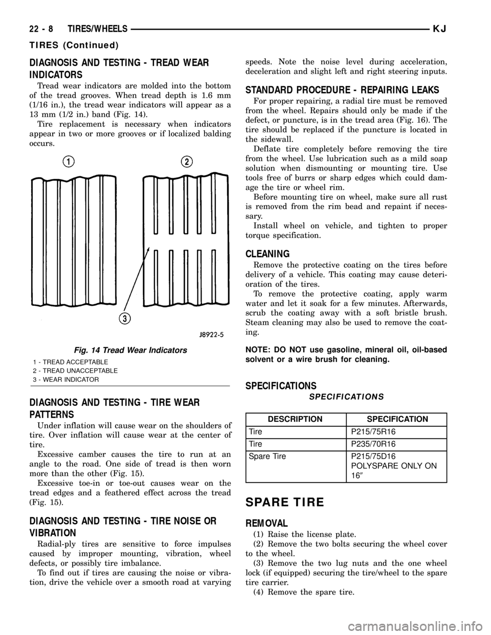
INDICATORS
Tread wear indicators are molded into the bottom
of the tread grooves. When tread depth is 1.6 mm
(1/16 in.), the tread wear indicators will appear as a
13 mm (1/2 in.) band (Fig. 14).
Tire replacement is necessary when indicators
appear in two or more grooves or if localized balding
occurs.
DIAGNOSIS AND TESTING - TIRE WEAR
PATTERNS
Under inflation will cause wear on the shoulders of
tire. Over inflation will cause wear at the center of
tire.
Excessive camber causes the tire to run at an
angle to the road. One side of tread is then worn
more than the other (Fig. 15).
Excessive toe-in or toe-out causes wear on the
tread edges and a feathered effect across the tread
(Fig. 15).
DIAGNOSIS AND TESTING - TIRE NOISE OR
VIBRATION
Radial-ply tires are sensitive to force impulses
caused by improper mounting, vibration, wheel
defects, or possibly tire imbalance.
To find out if tires are causing the noise or vibra-
tion, drive the vehicle over a smooth road at varyingspeeds. Note the noise level during acceleration,
deceleration and slight left and right steering inputs.
STANDARD PROCEDURE - REPAIRING LEAKS
For proper repairing, a radial tire must be removed
from the wheel. Repairs should only be made if the
defect, or puncture, is in the tread area (Fig. 16). The
tire should be replaced if the puncture is located in
the sidewall.
Deflate tire completely before removing the tire
from the wheel. Use lubrication such as a mild soap
solution when dismounting or mounting tire. Use
tools free of burrs or sharp edges which could dam-
age the tire or wheel rim.
Before mounting tire on wheel, make sure all rust
is removed from the rim bead and repaint if neces-
sary.
Install wheel on vehicle, and tighten to proper
torque specification.
CLEANING
Remove the protective coating on the tires before
delivery of a vehicle. This coating may cause deteri-
oration of the tires.
To remove the protective coating, apply warm
water and let it soak for a few minutes. Afterwards,
scrub the coating away with a soft bristle brush.
Steam cleaning may also be used to remove the coat-
ing.
NOTE: DO NOT use gasoline, mineral oil, oil-based
solvent or a wire brush for cleaning.
SPECIFICATIONS
SPECIFICATIONS
DESCRIPTION SPECIFICATION
Tire P215/75R16
Tire P235/70R16
Spare Tire P215/75D16
POLYSPARE ONLY ON
169
SPARE TIRE
REMOVAL
(1) Raise the license plate.
(2) Remove the two bolts securing the wheel cover
to the wheel.
(3) Remove the two lug nuts and the one wheel
lock (if equipped) securing the tire/wheel to the spare
tire carrier.
(4) Remove the spare tire.
Fig. 14 Tread Wear Indicators
1 - TREAD ACCEPTABLE
2 - TREAD UNACCEPTABLE
3 - WEAR INDICATOR
22 - 8 TIRES/WHEELSKJ
TIRES (Continued)
Page 1467 of 1803

DIAGNOSIS AND TESTING
DIAGNOSIS AND TESTING - WATER LEAKS
Water leaks can be caused by poor sealing,
improper body component alignment, body seam
porosity, missing plugs, or blocked drain holes. Cen-
trifugal and gravitational force can cause water to
drip from a location away from the actual leak point,
making leak detection difficult. All body sealing
points should be water tight in normal wet-driving
conditions. Water flowing downward from the front of
the vehicle should not enter the passenger or luggage
compartment. Moving sealing surfaces will not
always seal water tight under all conditions. At
times, side glass or door seals will allow water to
enter the passenger compartment during high pres-
sure washing or hard driving rain (severe) condi-
tions. Overcompensating on door or glass
adjustments to stop a water leak that occurs under
severe conditions can cause premature seal wear and
excessive closing or latching effort. After completing
a repair, water test vehicle to verify leak has stopped
before returning vehicle to use.
VISUAL INSPECTION BEFORE WATER LEAK TESTS
Verify that floor and body plugs are in place, body
drains are clear, and body components are properly
aligned and sealed. If component alignment or seal-
ing is necessary, refer to the appropriate section of
this group for proper procedures.
WATER LEAK TESTS
WARNING: DO NOT USE ELECTRIC SHOP LIGHTS
OR TOOLS IN WATER TEST AREA. PERSONAL
INJURY CAN RESULT.
When the conditions causing a water leak have
been determined, simulate the conditions as closely
as possible.
²If a leak occurs with the vehicle parked in a
steady light rain, flood the leak area with an open-
ended garden hose.
²If a leak occurs while driving at highway speeds
in a steady rain, test the leak area with a reasonable
velocity stream or fan spray of water. Direct the
spray in a direction comparable to actual conditions.
²If a leak occurs when the vehicle is parked on an
incline, hoist the end or side of the vehicle to simu-
late this condition. This method can be used when
the leak occurs when the vehicle accelerates, stops or
turns. If the leak occurs on acceleration, hoist the
front of the vehicle. If the leak occurs when braking,
hoist the back of the vehicle. If the leak occurs on left
turns, hoist the left side of the vehicle. If the leak
occurs on right turns, hoist the right side of the vehi-cle. For hoisting recommendations refer to Group 0,
Lubrication and Maintenance, General Information
section.
WATER LEAK DETECTION
To detect a water leak point-of-entry, do a water
test and watch for water tracks or droplets forming
on the inside of the vehicle. If necessary, remove inte-
rior trim covers or panels to gain visual access to the
leak area. If the hose cannot be positioned without
being held, have someone help do the water test.
Some water leaks must be tested for a considerable
length of time to become apparent. When a leak
appears, find the highest point of the water track or
drop. The highest point usually will show the point of
entry. After leak point has been found, repair the
leak and water test to verify that the leak has
stopped.
Locating the entry point of water that is leaking
into a cavity between panels can be difficult. The
trapped water may splash or run from the cavity,
often at a distance from the entry point. Most water
leaks of this type become apparent after accelerating,
stopping, turning, or when on an incline.
MIRROR INSPECTION METHOD
When a leak point area is visually obstructed, use
a suitable mirror to gain visual access. A mirror can
also be used to deflect light to a limited-access area
to assist in locating a leak point.
BRIGHT LIGHT LEAK TEST METHOD
Some water leaks in the luggage compartment can
be detected without water testing. Position the vehi-
cle in a brightly lit area. From inside the darkened
luggage compartment inspect around seals and body
seams. If necessary, have a helper direct a drop light
over the suspected leak areas around the luggage
compartment. If light is visible through a normally
sealed location, water could enter through the open-
ing.
PRESSURIZED LEAK TEST METHOD
When a water leak into the passenger compart-
ment cannot be detected by water testing, pressurize
the passenger compartment and soap test exterior of
the vehicle. To pressurize the passenger compart-
ment, close all doors and windows, start engine, and
set heater control to high blower in HEAT position. If
engine can not be started, connect a charger to the
battery to ensure adequate voltage to the blower.
With interior pressurized, apply dish detergent solu-
tion to suspected leak area on the exterior of the
vehicle. Apply detergent solution with spray device or
soft bristle brush. If soap bubbles occur at a body
seam, joint, seal or gasket, the leak entry point could
be at that location.
23 - 2 BODYKJ
BODY (Continued)
Page 1607 of 1803

(2) Install the three screws.
(3) Install the fuel cap.
GRILLE
REMOVAL
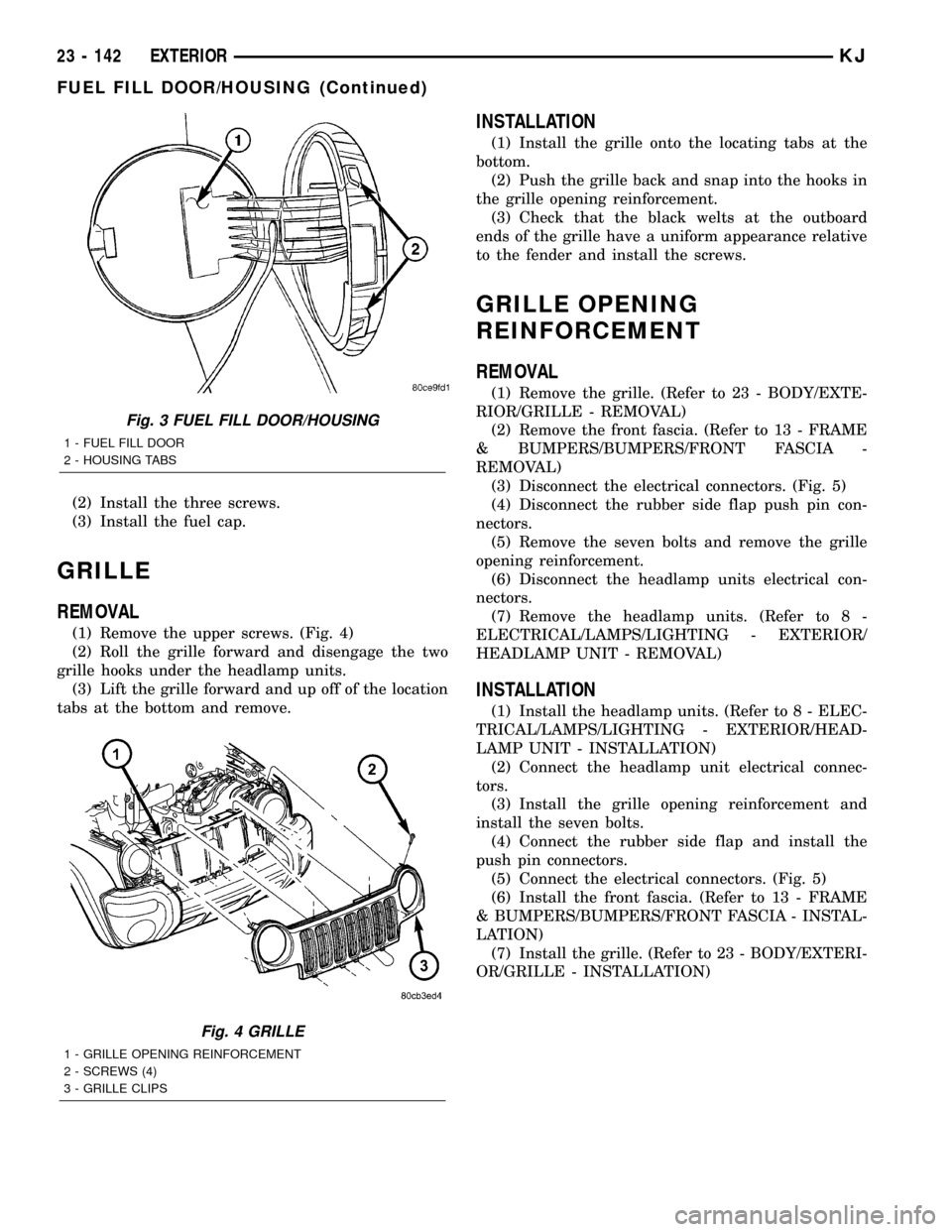
(1) Remove the upper screws. (Fig. 4)
(2) Roll the grille forward and disengage the two
grille hooks under the headlamp units.
(3) Lift the grille forward and up off of the location
tabs at the bottom and remove.
INSTALLATION
(1) Install the grille onto the locating tabs at the
bottom.
(2) Push the grille back and snap into the hooks in
the grille opening reinforcement.
(3) Check that the black welts at the outboard
ends of the grille have a uniform appearance relative
to the fender and install the screws.
GRILLE OPENING
REINFORCEMENT
REMOVAL
(1) Remove the grille. (Refer to 23 - BODY/EXTE-
RIOR/GRILLE - REMOVAL)
(2) Remove the front fascia. (Refer to 13 - FRAME
& BUMPERS/BUMPERS/FRONT FASCIA -
REMOVAL)
(3) Disconnect the electrical connectors. (Fig. 5)
(4) Disconnect the rubber side flap push pin con-
nectors.
(5) Remove the seven bolts and remove the grille
opening reinforcement.
(6) Disconnect the headlamp units electrical con-
nectors.
(7) Remove the headlamp units. (Refer to 8 -
ELECTRICAL/LAMPS/LIGHTING - EXTERIOR/
HEADLAMP UNIT - REMOVAL)
INSTALLATION
(1) Install the headlamp units. (Refer to 8 - ELEC-
TRICAL/LAMPS/LIGHTING - EXTERIOR/HEAD-
LAMP UNIT - INSTALLATION)
(2) Connect the headlamp unit electrical connec-
tors.
(3) Install the grille opening reinforcement and
install the seven bolts.
(4) Connect the rubber side flap and install the
push pin connectors.
(5) Connect the electrical connectors. (Fig. 5)
(6) Install the front fascia. (Refer to 13 - FRAME
& BUMPERS/BUMPERS/FRONT FASCIA - INSTAL-
LATION)
(7) Install the grille. (Refer to 23 - BODY/EXTERI-
OR/GRILLE - INSTALLATION)
Fig. 3 FUEL FILL DOOR/HOUSING
1 - FUEL FILL DOOR
2 - HOUSING TABS
Fig. 4 GRILLE
1 - GRILLE OPENING REINFORCEMENT
2 - SCREWS (4)
3 - GRILLE CLIPS
23 - 142 EXTERIORKJ
FUEL FILL DOOR/HOUSING (Continued)
Page 1614 of 1803

(1) Open the glove box.
(2) Remove the two striker screws and remove the
latch striker.
INSTALLATION
WARNING: ON VEHICLES EQUIPPED WITH AIR-
BAGS, DISABLE THE AIRBAG SYSTEM BEFORE
ATTEMPTING ANY STEERING WHEEL, STEERING
COLUMN, SEAT BELT TENSIONER, OR INSTRU-
MENT PANEL COMPONENT DIAGNOSIS OR SER-
VICE. DISCONNECT AND ISOLATE THE BATTERY
NEGATIVE (GROUND) CABLE, THEN WAIT TWO
MINUTES FOR THE AIRBAG SYSTEM CAPACITOR
TO DISCHARGE BEFORE PERFORMING FURTHER
DIAGNOSIS OR SERVICE. THIS IS THE ONLY SURE
WAY TO DISABLE THE AIRBAG SYSTEM. FAILURE
TO TAKE THE PROPER PRECAUTIONS COULD
RESULT IN ACCIDENTAL AIRBAG DEPLOYMENT
AND POSSIBLE PERSONAL INJURY.
(1) Install the striker and install the two screws.
(2) Loosen the screws to adjust if necessary.
INSTRUMENT PANEL
ASSEMBLY
REMOVAL
WARNING: ON VEHICLES EQUIPPED WITH AIR-
BAGS, DISABLE THE AIRBAG SYSTEM BEFORE
ATTEMPTING ANY STEERING WHEEL, STEERING
COLUMN, OR INSTRUMENT PANEL COMPONENT
DIAGNOSIS OR SERVICE. DISCONNECT AND ISO-
LATE THE BATTERY NEGATIVE (GROUND) CABLE,
THEN WAIT TWO MINUTES FOR THE AIRBAG SYS-
TEM CAPACITOR TO DISCHARGE BEFORE PER-
FORMING FURTHER DIAGNOSIS OR SERVICE. THIS
IS THE ONLY SURE WAY TO DISABLE THE AIRBAG
SYSTEM. FAILURE TO TAKE THE PROPER PRE-
CAUTIONS COULD RESULT IN ACCIDENTAL AIR-
BAG DEPLOYMENT AND POSSIBLE PERSONAL
INJURY.
NOTE: Before starting this procedure, be certain to
turn the steering wheel until the front wheels are in
the straight-ahead position.(1) Disconnect and isolate the battery negative
cable.
(2) Remove the instrument panel top cover. (Refer
to 23 - BODY/INSTRUMENT PANEL/INSTRUMENT
PANEL TOP COVER - REMOVAL)
(3) Remove the speakers.
(4) Remove the floor console. (Refer to 23 - BODY/
INTERIOR/FLOOR CONSOLE - REMOVAL)
(5) Remove the radio. (Refer to 8 - ELECTRICAL/
AUDIO/RADIO - REMOVAL)
(6) Remove the four nuts and remove the center
support bracket. (Fig. 6)
(7) Remove the steering column. (Refer to 19 -
STEERING/COLUMN - REMOVAL)
(8) Remove the drivers side cowl trim cover. (Refer
to 23 - BODY/INTERIOR/COWL TRIM COVER -
REMOVAL)
(9) Disconnect the wire harness connector behind
the drivers side cowl trim cover.
(10) Disconnect the green and light blue wire har-
ness bulk connectors at the junction block. (Fig. 1)
(11) Disconnect the electrical connector at the
inner side of the pedal support bracket. (Fig. 2)
(12) Remove the two bolts at the front of the pedal
support bracket. (Fig. 2)
(13) Remove the two bolts from the bottom side of
the pedal support bracket. (Fig. 2)
Fig. 1 JUNCTION BLOCK CONNECTORS
1 - ELECTRICAL CONNECTOR
2 - ELECTRICAL CONNECTOR
3 - PEDAL SUPPORT BRACKET
4 - JUNCTION BLOCK
KJINSTRUMENT PANEL 23 - 149
GLOVE BOX LATCH STRIKER (Continued)
Page 1624 of 1803

HEADLINER
REMOVAL
(1) Remove the a-pillar trim. (Refer to 23 - BODY/
INTERIOR/A-PILLAR TRIM AND GRAB HANDLE -
REMOVAL)
(2) Remove the visors. (Refer to 23 - BODY/INTE-
RIOR/SUN VISOR - REMOVAL)
(3) Remove the sun visor support. (Refer to 23 -
BODY/INTERIOR/SUN VISOR SUPPORT -
REMOVAL)
(4) Remove the overhead console. (Refer to 8 -
ELECTRICAL/OVERHEAD CONSOLE - REMOVAL)
(5) Cut rear washer hose at the mark about half-
way up the a-pillar.
(6) Remove the upper b-pillar trim. (Refer to 23 -
BODY/INTERIOR/B-PILLAR UPPER TRIM -
REMOVAL)
(7) Remove the assist handles. (Refer to 23 -
BODY/INTERIOR/ASSIST HANDLE - REMOVAL)
(8) Remove the quarter trim. (Refer to 23 - BODY/
INTERIOR/QUARTER TRIM PANEL - REMOVAL)
(9) Disconnect the electrical connector along the
left d-pillar and remove the ground wire.
(10) Remove the dome light in the rear.
(11) Remove the sunroof opening trim lace, if
equipped. (Refer to 23 - BODY/SUNROOF/OPENING
TRIM LACE - REMOVAL)(12) Remove the rear washer nozzle.
(13) Remove the headliner.
INSTALLATION
(1) Install the headliner.
(2) Install the assist handles. (Refer to 23 - BODY/
INTERIOR/ASSIST HANDLE - INSTALLATION)
(3) Install the visors. (Refer to 23 - BODY/INTERI-
OR/SUN VISOR - INSTALLATION)
(4) Install the visor supports. (Refer to 23 - BODY/
INTERIOR/SUN VISOR SUPPORT - INSTALLA-
TION)
(5) Install the overhead console. (Refer to 8 -
ELECTRICAL/OVERHEAD CONSOLE - INSTALLA-
TION)
(6) Connect the rear washer hose, previously cut,
with a hose junction.
(7) Install the a-pillar trim and grab handles.
(Refer to 23 - BODY/INTERIOR/A-PILLAR TRIM -
INSTALLATION)
(8) Install the upper b-pillar trim. (Refer to 23 -
BODY/INTERIOR/B-PILLAR UPPER TRIM -
INSTALLATION)
(9) Install the rear washer nozzle.
(10) Connect the electrical connector and ground
wire at the left d-pillar.
(11) Install the quarter trim panels. (Refer to 23 -
BODY/INTERIOR/QUARTER TRIM PANEL -
INSTALLATION)
(12) Install the rear dome light.
(13) Install the sunroof opening trim lace, if
equipped. (Refer to 23 - BODY/SUNROOF/OPENING
TRIM LACE - INSTALLATION)
QUARTER TRIM PANEL
REMOVAL
(1) Using a trim stick C-4755 or equivalent,
remove the rear header trim.
(2) Using a trim stick C-4755 or equivalent,
remove the rear sill plate.
(3) Remove the hook pin type connector.
(4) Fold down the rear seat.
(5) Remove the seat belt anchor and pivot. (Refer
to 8 - ELECTRICAL/RESTRAINTS/SEAT BELT &
RETRACTOR - REMOVAL)
(6) Remove the belt access panel. (Fig. 4)
(7) Remove the storage cover.
(8) Disconnect the 12v power supply electrical con-
nector, if equipped.
INSTALLATION
(1) Position the 12v power supply electrical con-
nector, if equipped.
(2) Install the storage cover.
Fig. 3 FLOOR CONSOLE
1 - SHIFT BEZEL
2 - ACCESSORY CUP
3 - BOLTS (4)
4 - FLOOR CONSOLE
KJINTERIOR 23 - 159
FLOOR CONSOLE LID LATCH (Continued)
Page 1627 of 1803

PAINT
TABLE OF CONTENTS
page page
PAINT
SPECIFICATIONS - PAINT CODES.........162
PAINT CODE
DESCRIPTION........................162
BASE COAT/CLEAR COAT FINISH
DESCRIPTION........................162PAINT TOUCH-UP
DESCRIPTION........................163
FINESSE SANDING/BUFFING & POLISHING
DESCRIPTION........................163
PAINT
SPECIFICATIONS - PAINT CODES
EXTERIOR COLORS
EXTERIOR COLOR DAIMLERCHRYSLER
CODE
Black Clear Coat DX8
Bright Cactus Green
Pearl CoatAFM
Bright Silver Metallic
Clear CoatWS2
Dark Garnet Red Pearl
CoatXRV
Flame Red Clear Coat PR4
Patriot Blue Pearl Coat WB7
Salsa Red Pearl Coat WE5
Shale Green Metallic
Clear CoatXGR
Steel Blue Pearl Coat XBQ
Stone White Clear Coat SW1
Woodland Brown Satin
GlowYU2
INTERIOR COLORS
INTERIOR COLOR DAIMLERCHRYSLER
CODE
Taupe L5
Dark Slate Gray DV
Dark Slate Gray/Light
TaupeD2
Taupe/Light Taupe L2
ACCESSORY COLORS
PART COLOR DAIMLERCHRYSLER
CODE
Renegade
Roof
Rack/Light
BarDeep Gray ZSP
Sport
Fascia/Wheel
FlareDark Neutral
GrayHS5
PAINT CODE
DESCRIPTION
The paint code is identified on the Vehicle Safety
Certification Label which is located on the drivers
door shut face. The color names provided in the Paint
and Trim Code Description chart are the color names
used on most repair product containers.
BASE COAT/CLEAR COAT
FINISH
DESCRIPTION
The original equipment finish is a multi step pro-
cess that involves cleaning, applying electro de-posi-
tion (E-coat), anti-chip primer, base coat, and clear
coat steps.
On most vehicles a two-part paint application (base
coat/clear coat) is used. Color paint that is applied to
primer is called base coat. The clear coat protects the
base coat from ultraviolet light and provides a dura-
ble high-gloss finish.
23 - 162 PAINTKJ