2002 JEEP LIBERTY pistons
[x] Cancel search: pistonsPage 1322 of 1803
INSPECTION
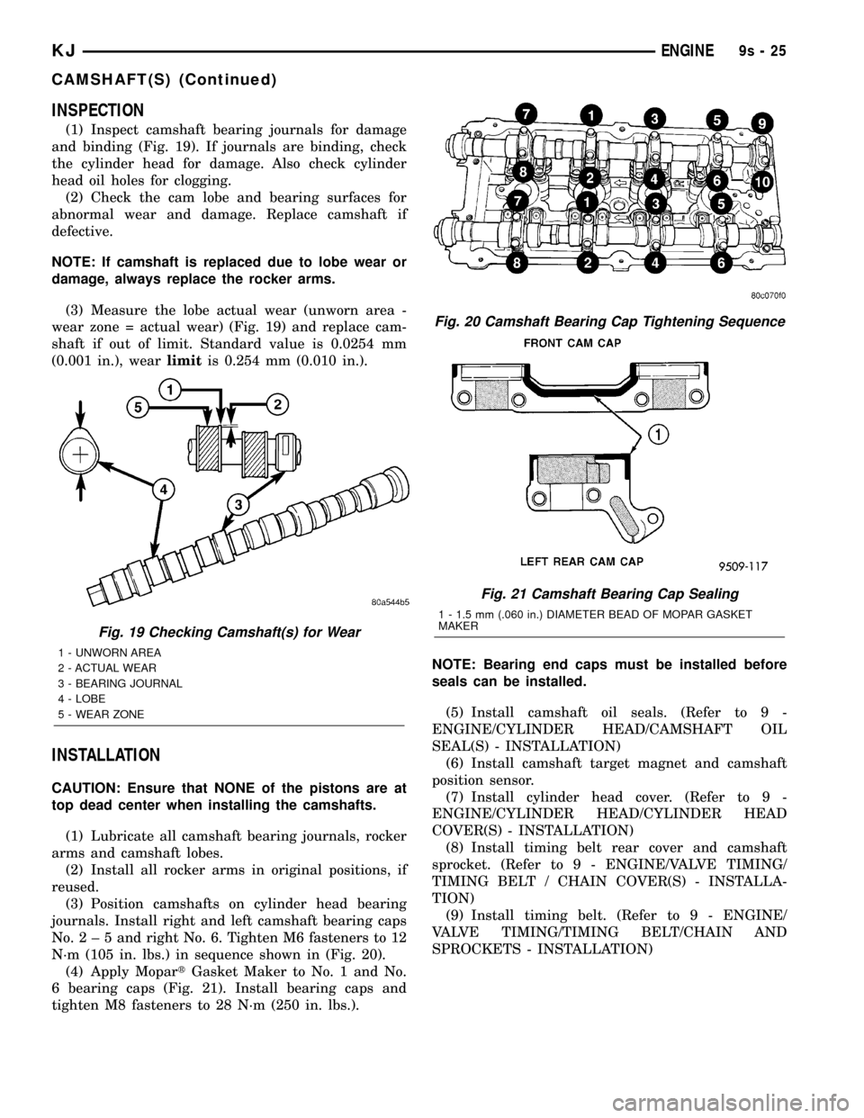
(1) Inspect camshaft bearing journals for damage
and binding (Fig. 19). If journals are binding, check
the cylinder head for damage. Also check cylinder
head oil holes for clogging.
(2) Check the cam lobe and bearing surfaces for
abnormal wear and damage. Replace camshaft if
defective.
NOTE: If camshaft is replaced due to lobe wear or
damage, always replace the rocker arms.
(3) Measure the lobe actual wear (unworn area -
wear zone = actual wear) (Fig. 19) and replace cam-
shaft if out of limit. Standard value is 0.0254 mm
(0.001 in.), wearlimitis 0.254 mm (0.010 in.).
INSTALLATION
CAUTION: Ensure that NONE of the pistons are at
top dead center when installing the camshafts.
(1) Lubricate all camshaft bearing journals, rocker
arms and camshaft lobes.
(2) Install all rocker arms in original positions, if
reused.
(3) Position camshafts on cylinder head bearing
journals. Install right and left camshaft bearing caps
No.2±5andright No. 6. Tighten M6 fasteners to 12
N´m (105 in. lbs.) in sequence shown in (Fig. 20).
(4) Apply MopartGasket Maker to No. 1 and No.
6 bearing caps (Fig. 21). Install bearing caps and
tighten M8 fasteners to 28 N´m (250 in. lbs.).NOTE: Bearing end caps must be installed before
seals can be installed.
(5) Install camshaft oil seals. (Refer to 9 -
ENGINE/CYLINDER HEAD/CAMSHAFT OIL
SEAL(S) - INSTALLATION)
(6) Install camshaft target magnet and camshaft
position sensor.
(7) Install cylinder head cover. (Refer to 9 -
ENGINE/CYLINDER HEAD/CYLINDER HEAD
COVER(S) - INSTALLATION)
(8) Install timing belt rear cover and camshaft
sprocket. (Refer to 9 - ENGINE/VALVE TIMING/
TIMING BELT / CHAIN COVER(S) - INSTALLA-
TION)
(9) Install timing belt. (Refer to 9 - ENGINE/
VALVE TIMING/TIMING BELT/CHAIN AND
SPROCKETS - INSTALLATION)
Fig. 19 Checking Camshaft(s) for Wear
1 - UNWORN AREA
2 - ACTUAL WEAR
3 - BEARING JOURNAL
4 - LOBE
5 - WEAR ZONE
Fig. 20 Camshaft Bearing Cap Tightening Sequence
Fig. 21 Camshaft Bearing Cap Sealing
1 - 1.5 mm (.060 in.) DIAMETER BEAD OF MOPAR GASKET
MAKER
KJENGINE9s-25
CAMSHAFT(S) (Continued)
Page 1328 of 1803
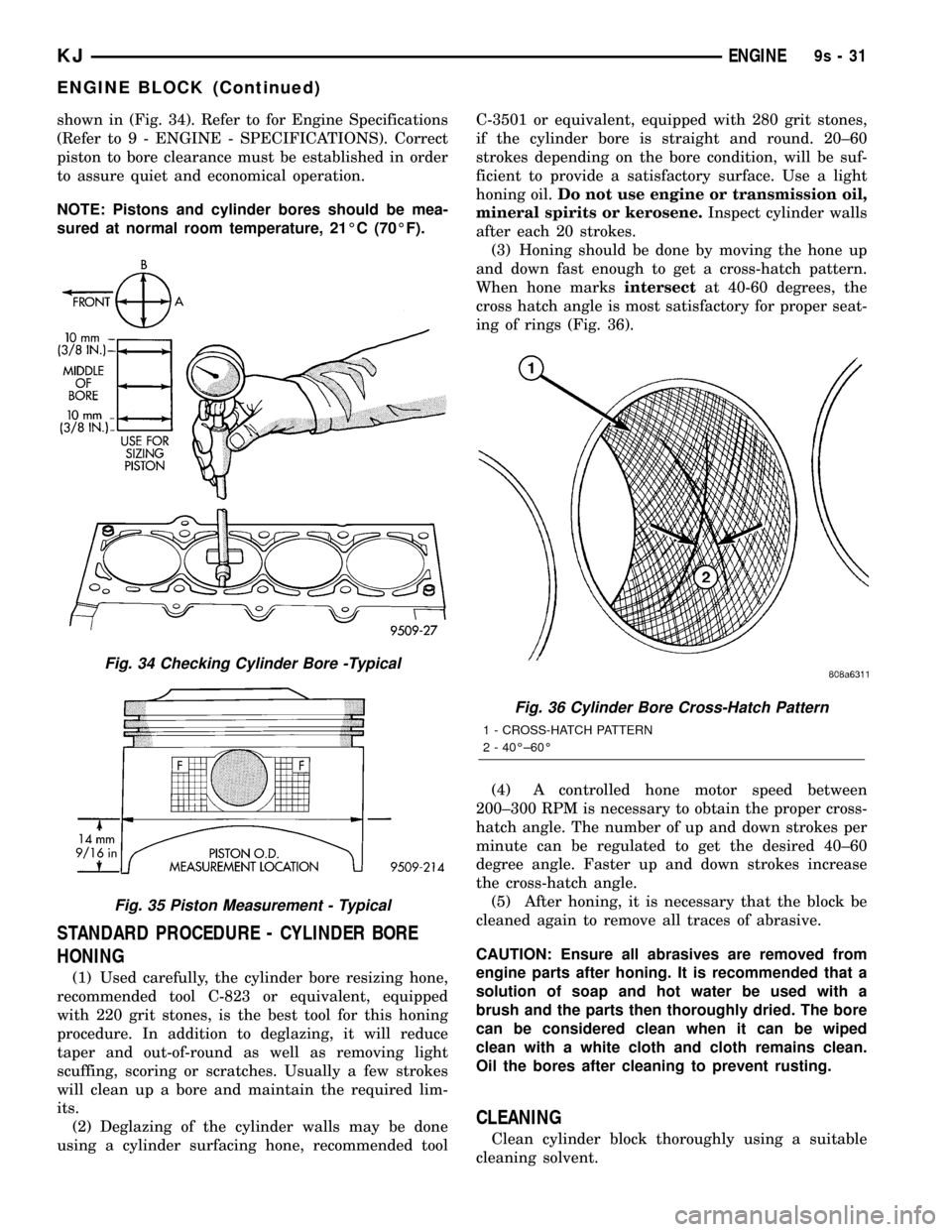
shown in (Fig. 34). Refer to for Engine Specifications
(Refer to 9 - ENGINE - SPECIFICATIONS). Correct
piston to bore clearance must be established in order
to assure quiet and economical operation.
NOTE: Pistons and cylinder bores should be mea-
sured at normal room temperature, 21ÉC (70ÉF).
STANDARD PROCEDURE - CYLINDER BORE
HONING
(1) Used carefully, the cylinder bore resizing hone,
recommended tool C-823 or equivalent, equipped
with 220 grit stones, is the best tool for this honing
procedure. In addition to deglazing, it will reduce
taper and out-of-round as well as removing light
scuffing, scoring or scratches. Usually a few strokes
will clean up a bore and maintain the required lim-
its.
(2) Deglazing of the cylinder walls may be done
using a cylinder surfacing hone, recommended toolC-3501 or equivalent, equipped with 280 grit stones,
if the cylinder bore is straight and round. 20±60
strokes depending on the bore condition, will be suf-
ficient to provide a satisfactory surface. Use a light
honing oil.Do not use engine or transmission oil,
mineral spirits or kerosene.Inspect cylinder walls
after each 20 strokes.
(3) Honing should be done by moving the hone up
and down fast enough to get a cross-hatch pattern.
When hone marksintersectat 40-60 degrees, the
cross hatch angle is most satisfactory for proper seat-
ing of rings (Fig. 36).
(4) A controlled hone motor speed between
200±300 RPM is necessary to obtain the proper cross-
hatch angle. The number of up and down strokes per
minute can be regulated to get the desired 40±60
degree angle. Faster up and down strokes increase
the cross-hatch angle.
(5) After honing, it is necessary that the block be
cleaned again to remove all traces of abrasive.
CAUTION: Ensure all abrasives are removed from
engine parts after honing. It is recommended that a
solution of soap and hot water be used with a
brush and the parts then thoroughly dried. The bore
can be considered clean when it can be wiped
clean with a white cloth and cloth remains clean.
Oil the bores after cleaning to prevent rusting.
CLEANING
Clean cylinder block thoroughly using a suitable
cleaning solvent.
Fig. 34 Checking Cylinder Bore -Typical
Fig. 35 Piston Measurement - Typical
Fig. 36 Cylinder Bore Cross-Hatch Pattern
1 - CROSS-HATCH PATTERN
2 - 40ɱ60É
KJENGINE9s-31
ENGINE BLOCK (Continued)
Page 1329 of 1803
INSPECTION
ENGINE BLOCK
(1) Clean cylinder block thoroughly and check all
core hole plugs for evidence of leaking.
(2) If new core plugs are to be installed, (Refer to 9
- ENGINE - STANDARD PROCEDURE - ENGINE
CORE AND OIL GALLERY PLUGS).
(3) Examine block and cylinder bores for cracks or
fractures.
(4) Check block deck surfaces for flatness. Deck
surface must be within service limit of 0.1 mm (0.004
in.).
CYLINDER BORE
NOTE: The cylinder bores should be measured at
normal room temperature, 21ÉC (70ÉF).
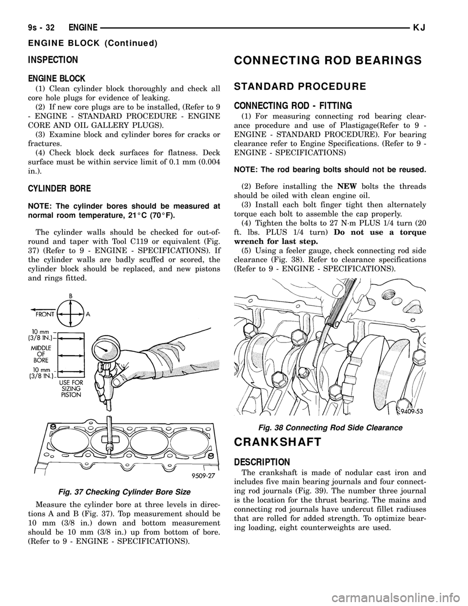
The cylinder walls should be checked for out-of-
round and taper with Tool C119 or equivalent (Fig.
37) (Refer to 9 - ENGINE - SPECIFICATIONS). If
the cylinder walls are badly scuffed or scored, the
cylinder block should be replaced, and new pistons
and rings fitted.
Measure the cylinder bore at three levels in direc-
tions A and B (Fig. 37). Top measurement should be
10 mm (3/8 in.) down and bottom measurement
should be 10 mm (3/8 in.) up from bottom of bore.
(Refer to 9 - ENGINE - SPECIFICATIONS).
CONNECTING ROD BEARINGS
STANDARD PROCEDURE
CONNECTING ROD - FITTING
(1) For measuring connecting rod bearing clear-
ance procedure and use of Plastigage(Refer to 9 -
ENGINE - STANDARD PROCEDURE). For bearing
clearance refer to Engine Specifications. (Refer to 9 -
ENGINE - SPECIFICATIONS)
NOTE: The rod bearing bolts should not be reused.
(2) Before installing theNEWbolts the threads
should be oiled with clean engine oil.
(3) Install each bolt finger tight then alternately
torque each bolt to assemble the cap properly.
(4) Tighten the bolts to 27 N´m PLUS 1/4 turn (20
ft. lbs. PLUS 1/4 turn)Do not use a torque
wrench for last step.
(5) Using a feeler gauge, check connecting rod side
clearance (Fig. 38). Refer to clearance specifications
(Refer to 9 - ENGINE - SPECIFICATIONS).
CRANKSHAFT
DESCRIPTION
The crankshaft is made of nodular cast iron and
includes five main bearing journals and four connect-
ing rod journals (Fig. 39). The number three journal
is the location for the thrust bearing. The mains and
connecting rod journals have undercut fillet radiuses
that are rolled for added strength. To optimize bear-
ing loading, eight counterweights are used.
Fig. 37 Checking Cylinder Bore Size
Fig. 38 Connecting Rod Side Clearance
9s - 32 ENGINEKJ
ENGINE BLOCK (Continued)
Page 1337 of 1803
(4) Install flex plate. Apply MopartLock & Seal
Adhesive to bolt threads and tighten bolts to 95 N´m
(70 ft. lbs.).
(5) Install the transmission.
PISTON & CONNECTING ROD
DESCRIPTION
The pistons are made of a cast aluminum alloy.
The pistons have pressed-in pins attached to forged
powdered metal connecting rods. The pistons pin is
offset 1 mm (0.0394 in.) towards the thrust side of
the piston. The connecting rods are a cracked cap
design and are not repairable. Hex head cap screws
are used to provide alignment and durability in the
assembly. The pistons and connecting rods are ser-
viced as an assembly.
OPERATION
The piston and connecting rod is the link between
the combustion force to the crankshaft.
REMOVAL
NOTE: Cylinder Head must be removed before Pis-
tons and Rods. Refer to Cylinder Head Removal in
this section.
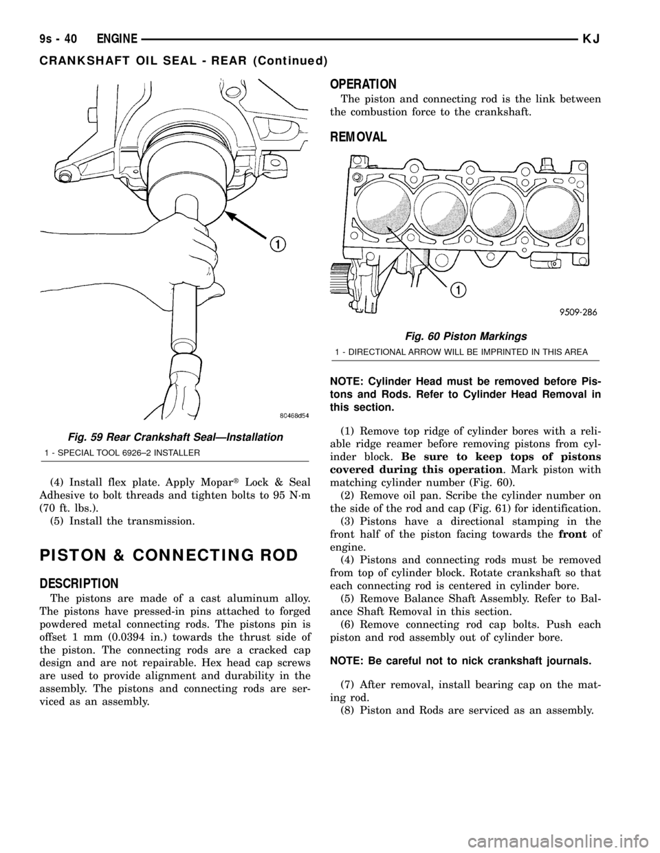
(1) Remove top ridge of cylinder bores with a reli-
able ridge reamer before removing pistons from cyl-
inder block.Be sure to keep tops of pistons
covered during this operation. Mark piston with
matching cylinder number (Fig. 60).
(2) Remove oil pan. Scribe the cylinder number on
the side of the rod and cap (Fig. 61) for identification.
(3) Pistons have a directional stamping in the
front half of the piston facing towards thefrontof
engine.
(4) Pistons and connecting rods must be removed
from top of cylinder block. Rotate crankshaft so that
each connecting rod is centered in cylinder bore.
(5) Remove Balance Shaft Assembly. Refer to Bal-
ance Shaft Removal in this section.
(6) Remove connecting rod cap bolts. Push each
piston and rod assembly out of cylinder bore.
NOTE: Be careful not to nick crankshaft journals.
(7) After removal, install bearing cap on the mat-
ing rod.
(8) Piston and Rods are serviced as an assembly.
Fig. 59 Rear Crankshaft SealÐInstallation
1 - SPECIAL TOOL 6926±2 INSTALLER
Fig. 60 Piston Markings
1 - DIRECTIONAL ARROW WILL BE IMPRINTED IN THIS AREA
9s - 40 ENGINEKJ
CRANKSHAFT OIL SEAL - REAR (Continued)
Page 1338 of 1803
INSTALLATION
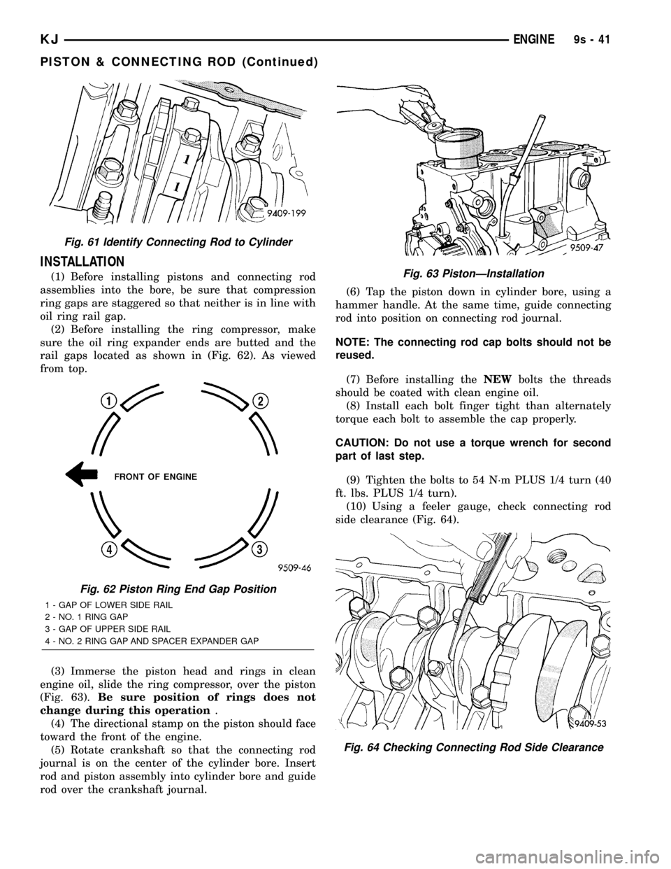
(1) Before installing pistons and connecting rod
assemblies into the bore, be sure that compression
ring gaps are staggered so that neither is in line with
oil ring rail gap.
(2) Before installing the ring compressor, make
sure the oil ring expander ends are butted and the
rail gaps located as shown in (Fig. 62). As viewed
from top.
(3) Immerse the piston head and rings in clean
engine oil, slide the ring compressor, over the piston
(Fig. 63).Be sure position of rings does not
change during this operation.
(4) The directional stamp on the piston should face
toward the front of the engine.
(5) Rotate crankshaft so that the connecting rod
journal is on the center of the cylinder bore. Insert
rod and piston assembly into cylinder bore and guide
rod over the crankshaft journal.(6) Tap the piston down in cylinder bore, using a
hammer handle. At the same time, guide connecting
rod into position on connecting rod journal.
NOTE: The connecting rod cap bolts should not be
reused.
(7) Before installing theNEWbolts the threads
should be coated with clean engine oil.
(8) Install each bolt finger tight than alternately
torque each bolt to assemble the cap properly.
CAUTION: Do not use a torque wrench for second
part of last step.
(9) Tighten the bolts to 54 N´m PLUS 1/4 turn (40
ft. lbs. PLUS 1/4 turn).
(10) Using a feeler gauge, check connecting rod
side clearance (Fig. 64).
Fig. 61 Identify Connecting Rod to Cylinder
Fig. 62 Piston Ring End Gap Position
1 - GAP OF LOWER SIDE RAIL
2 - NO. 1 RING GAP
3 - GAP OF UPPER SIDE RAIL
4 - NO. 2 RING GAP AND SPACER EXPANDER GAP
Fig. 63 PistonÐInstallation
Fig. 64 Checking Connecting Rod Side Clearance
KJENGINE9s-41
PISTON & CONNECTING ROD (Continued)
Page 1757 of 1803
OPERATION - DESCRIPTION, MODES OF . . 8E-11
OPERATION - DIAGNOSIS AND TESTING,
AIR CHECKING TRANSMISSION
CLUTCH............................21-80
ORDER, 2.4L 4-CYLINDER - ENGINE
FIRING..............................8I-2
ORDER, 3.7L V-6 - ENGINE FIRING........8I-2
ORIFICE TUBE - DESCRIPTION, A/C......24-50
ORIFICE TUBE - INSTALLATION, A/C......24-50
ORIFICE TUBE - OPERATION, A/C........24-50
ORIFICE TUBE - REMOVAL, A/C.........24-50
ORVR - DESCRIPTION.................25-29
ORVR - OPERATION..................25-29
OUT - ADJUSTMENT, LOCK..............5-30
OUTBOARD SEAT BELT & RETRACTOR -
INSTALLATION, REAR.................8O-34
OUTBOARD SEAT BELT & RETRACTOR -
REMOVAL, REAR....................8O-33
OUTER BELT MOLDING - INSTALLATION,
FRONT DOOR......................23-186
OUTER BELT MOLDING - INSTALLATION,
REAR DOOR.......................23-186
OUTER BELT MOLDING - REMOVAL,
FRONT DOOR......................23-186
OUTER BELT MOLDING - REMOVAL,
REAR DOOR.......................23-186
OUTER TIE ROD END REMOVAL TOOL,
SPECIAL TOOLS.....................19-15
OUTLET - DESCRIPTION, CIGAR
LIGHTER.........................8W-97-2
OUTLET - DESCRIPTION, POWER......8W-97-11
OUTLET - DIAGNOSIS AND TESTING,
CIGAR LIGHTER...................8W-97-2
OUTLET - DIAGNOSIS AND TESTING,
POWER.........................8W-97-11
OUTLET - INSTALLATION, POWER....8W-97-13
OUTLET - OPERATION, CIGAR LIGHTER . 8W-97-2
OUTLET - OPERATION, POWER......8W-97-11
OUTLET - REMOVAL, POWER........8W-97-12
OUTLET BARRELS - INSTALLATION,
PANEL.............................24-29
OUTLET BARRELS - REMOVAL, PANEL . . . 24-29
OUTLETS - DESCRIPTION, DEMISTER....24-29
OUTPUT - DESCRIPTION, PCM...........8I-4
OUTPUT - OPERATION, PCM............14-33
OUTPUT - OPERATION, PCM.............8I-4
OUTPUT SHAFT SEAL - INSTALLATION,
FRONT......................21-208,21-246
OUTPUT SHAFT SEAL - INSTALLATION,
REAR.............................21-212
OUTPUT SHAFT SEAL - REMOVAL,
FRONT......................21-208,21-246
OUTPUT SHAFT SEAL - REMOVAL, REAR . 21-210
OUTPUT SPEED SENSOR - DESCRIPTION . 21-152
OUTPUT SPEED SENSOR -
INSTALLATION......................21-152
OUTPUT SPEED SENSOR - OPERATION . . 21-152
OUTPUT SPEED SENSOR - REMOVAL . . . 21-152
OVERDRIVE OFF INDICATOR -
DESCRIPTION.......................8J-26
OVERDRIVE OFF INDICATOR -
OPERATION.........................8J-26
OVERDRIVE SWITCH - DESCRIPTION....21-153
OVERDRIVE SWITCH - OPERATION.....21-153
OVERHEAD CONSOLE - DESCRIPTION....8M-1
OVERHEAD CONSOLE - OPERATION......8M-2
OVERHEAD CONSOLE, REMOVAL........8M-4
OVERRIDE RELAY - DESCRIPTION,
CLUTCH SWITCH......................6-10
OVERRIDE RELAY - INSTALLATION,
CLUTCH SWITCH......................6-10
OVERRIDE RELAY - OPERATION,
CLUTCH SWITCH......................6-10
OVERRIDE RELAY - REMOVAL, CLUTCH
SWITCH.............................6-10
OXYGEN SENSOR - DESCRIPTION.......14-40
OXYGEN SENSOR - INSTALLATION.......14-43
OXYGEN SENSOR - OPERATION.........14-40
OXYGEN SENSOR - REMOVAL..........14-41
PADS - INSTALLATION, FRONT BRAKE.....5-11
PADS - REMOVAL, FRONT BRAKE........5-11
PAINT CODE - DESCRIPTION..........23-162
PAINT CODES - SPECIFICATIONS.......23-162
PAINT TOUCH-UP - DESCRIPTION
......23-163
PAN - CLEANING, OIL
..................9-63
PAN - DESCRIPTION, OIL
...............9-63
PAN - INSPECTION, OIL
................9-63
PAN - INSTALLATION, OIL
...............9-64PAN - REMOVAL, OIL..................9-63
PANEL - DESCRIPTION, LATCH - ACCESS . 23-139
PANEL - INSTALLATION, GLASS........23-178
PANEL - INSTALLATION, LATCH -
ACCESS...........................23-139
PANEL - INSTALLATION, QUARTER TRIM . 23-159
PANEL - INSTALLATION, TRIM . . . 23-126,23-132,
23-138
PANEL - REMOVAL, GLASS............23-178
PANEL - REMOVAL, LATCH - ACCESS . . . 23-139
PANEL - REMOVAL, QUARTER TRIM....23-159
PANEL - REMOVAL, TRIM . 23-125,23-132,23-138
PANEL ADJUSTMENT, ADJUSTMENTS -
SUNROOF GLASS...................23-178
PANEL ANTENNA CABLE -
INSTALLATION, INSTRUMENT............8A-8
PANEL ANTENNA CABLE - REMOVAL,
INSTRUMENT........................8A-7
PANEL ASSEMBLY - INSTALLATION,
INSTRUMENT......................23-151
PANEL ASSEMBLY - REMOVAL,
INSTRUMENT......................23-149
PANEL CENTER BEZEL - INSTALLATION,
INSTRUMENT......................23-154
PANEL CENTER BEZEL - REMOVAL,
INSTRUMENT......................23-154
PANEL DOOR - INSTALLATION..........24-36
PANEL DOOR ACTUATOR -
INSTALLATION.......................24-25
PANEL DOOR ACTUATOR - REMOVAL....24-24
PANEL DRIVER SIDE BEZELS -
INSTALLATION, INSTRUMENT..........23-154
PANEL DRIVER SIDE BEZELS -
REMOVAL, INSTRUMENT.............23-153
PANEL END CAP - INSTALLATION,
INSTRUMENT......................23-153
PANEL END CAP - REMOVAL,
INSTRUMENT......................23-153
PANEL OUTLET BARRELS -
INSTALLATION.......................24-29
PANEL OUTLET BARRELS - REMOVAL....24-29
PANEL PASSENGER SIDE BEZEL -
INSTALLATION, INSTRUMENT..........23-154
PANEL PASSENGER SIDE BEZEL -
REMOVAL, INSTRUMENT.............23-154
PANEL SEAL - INSTALLATION, GLASS . . . 23-178
PANEL SEAL - REMOVAL, GLASS.......23-178
PANEL TOP COVER - INSTALLATION,
INSTRUMENT......................23-153
PANEL TOP COVER - REMOVAL,
INSTRUMENT......................23-152
PARK - INTERLOCK CABLE -
INSTALLATION......................21-153
PARK - INTERLOCK CABLE - REMOVAL . . 21-153
PARK LAMP RELAY - DESCRIPTION......8L-54
PARK LAMP RELAY - DIAGNOSIS AND
TESTING...........................8L-55
PARK LAMP RELAY - INSTALLATION.....8L-56
PARK LAMP RELAY - OPERATION.......8L-54
PARK LAMP RELAY - REMOVAL.........8L-55
PARK RAMP - INSTALLATION, WIPER
ARM ..............................8R-43
PARK RAMP - REMOVAL, WIPER ARM . . . 8R-43
PARKING BRAKE - DESCRIPTION.........5-29
PARKING BRAKE - OPERATION...........5-29
PARK-INTERLOCK CABLE -
ADJUSTMENTS.....................21-154
PART TIME INDICATOR - DESCRIPTION . . . 8J-29
PART TIME INDICATOR - OPERATION.....8J-29
PASSENGER AIRBAG - DESCRIPTION....8O-27
PASSENGER AIRBAG - INSTALLATION....8O-29
PASSENGER AIRBAG - OPERATION......8O-27
PASSENGER AIRBAG - REMOVAL........8O-28
PASSENGER AIRBAG DOOR -
INSTALLATION......................8O-30
PASSENGER AIRBAG DOOR - REMOVAL . . 8O-29
PASSENGER AIRBAG MOUNTING
BRACKET - INSTALLATION.............8O-31
PASSENGER AIRBAG MOUNTING
BRACKET - REMOVAL
.................8O-31
PASSENGER SEAT HEATER SWITCH -
DESCRIPTION
.......................8G-14
PASSENGER SEAT HEATER SWITCH -
INSTALLATION
......................8G-15
PASSENGER SEAT HEATER SWITCH -
OPERATION
.........................8G-14
PASSENGER SEAT HEATER SWITCH -
REMOVAL
..........................8G-15PASSENGER SIDE BEZEL -
INSTALLATION, INSTRUMENT PANEL....23-154
PASSENGER SIDE BEZEL - REMOVAL,
INSTRUMENT PANEL.................23-154
PATTERNS - DIAGNOSIS AND TESTING,
TIRE WEAR..........................22-8
PCM - DESCRIPTION..................8E-11
PCM - OPERATION...................8E-14
PCM INPUT - OPERATION, ASD SENSE.....8I-4
PCM OUTPUT - DESCRIPTION............8I-4
PCM OUTPUT - OPERATION............14-33
PCM OUTPUT - OPERATION.............8I-4
PCM/SKIM PROGRAMMING - STANDARD
PROCEDURE.........................8E-1
PCV VALVE - DESCRIPTION............25-29
PCV VALVE - DIAGNOSIS AND TESTING . . . 25-31
PCV VALVE - INSTALLATION............25-32
PCV VALVE - OPERATION..............25-31
PCV VALVE - REMOVAL...............25-32
PEDAL - DESCRIPTION.................5-20
PEDAL - INSTALLATION................5-20
PEDAL - INSTALLATION, ACCELERATOR . . . 14-30
PEDAL - INSTALLATION, CLUTCH.........6-10
PEDAL - OPERATION...................5-20
PEDAL - REMOVAL....................5-20
PEDAL - REMOVAL, ACCELERATOR......14-29
PEDAL - REMOVAL, CLUTCH............6-10
PEDAL POSITION SWITCH -
DESCRIPTION, CLUTCH.................6-11
PEDAL POSITION SWITCH - DIAGNOSIS
AND TESTING, CLUTCH.................6-11
PEDAL POSITION SWITCH - OPERATION,
CLUTCH.............................6-11
PERFORMANCE - DIAGNOSIS AND
TESTING, A/C........................24-2
PERFORMANCE - DIAGNOSIS AND
TESTING, ENGINE DIAGNOSIS............9-4
PERFORMANCE - DIAGNOSIS AND
TESTING, HEATER.....................24-6
PILOT BEARING - INSTALLATION..........6-8
PILOT BEARING - REMOVAL..............6-8
PINION GEAR/RING GEAR -
INSTALLATION........................3-46
PINION GEAR/RING GEAR - REMOVAL.....3-44
PINION GEAR/RING GEAR/TONE RING -
INSTALLATION...................3-112,3-82
PINION GEAR/RING GEAR/TONE RING -
REMOVAL......................3-110,3-79
PINION SEAL - INSTALLATION . . 3-103,3-39,3-68
PINION SEAL - REMOVAL......3-102,3-38,3-68
PIPE - INSTALLATION, CROSS-OVER......11-3
PIPE - REMOVAL, CROSS-OVER..........11-3
PISTON & CONNECTING ROD -
DESCRIPTION........................9-49
PISTON FITTING - STANDARD
PROCEDURE.........................9-50
PISTON RING FITTING - STANDARD
PROCEDURE.........................9-52
PISTONS - DESCRIPTION.............21-155
PISTONS - OPERATION...............21-155
PLANETARY GEARTRAIN - ASSEMBLY . . . 21-160
PLANETARY GEARTRAIN - CLEANING....21-159
PLANETARY GEARTRAIN - DESCRIPTION . 21-157
PLANETARY GEARTRAIN -
DISASSEMBLY......................21-159
PLANETARY GEARTRAIN - INSPECTION . . 21-159
PLANETARY GEARTRAIN - OPERATION . . 21-157
PLATE - INSTALLATION, DOOR SILL
SCUFF............................23-157
PLATE - INSTALLATION, FLEX............9-49
PLATE - INSTALLATION, FRONT SKID......13-6
PLATE - INSTALLATION, FUEL TANK
SKID...............................13-9
PLATE - INSTALLATION, REAR DOOR
SCUFF............................23-160
PLATE - INSTALLATION, TRANSFER
CASE SKID..........................13-7
PLATE - REMOVAL, DOOR SILL SCUFF . . . 23-157
PLATE - REMOVAL, FLEX...............9-49
PLATE - REMOVAL, FRONT SKID.........13-6
PLATE - REMOVAL, FUEL TANK SKID
......13-9
PLATE - REMOVAL, REAR DOOR SCUFF
. . 23-160
PLATE - REMOVAL, TRANSFER CASE
SKID
...............................13-7
PLATE LAMP BULB - INSTALLATION,
LICENSE
...........................8L-45
PLATE LAMP BULB - REMOVAL,
LICENSE
...........................8L-44
18 INDEXKJ
Description Group-Page Description Group-Page Description Group-Page