2002 JEEP LIBERTY gas type
[x] Cancel search: gas typePage 1273 of 1803
OPERATION
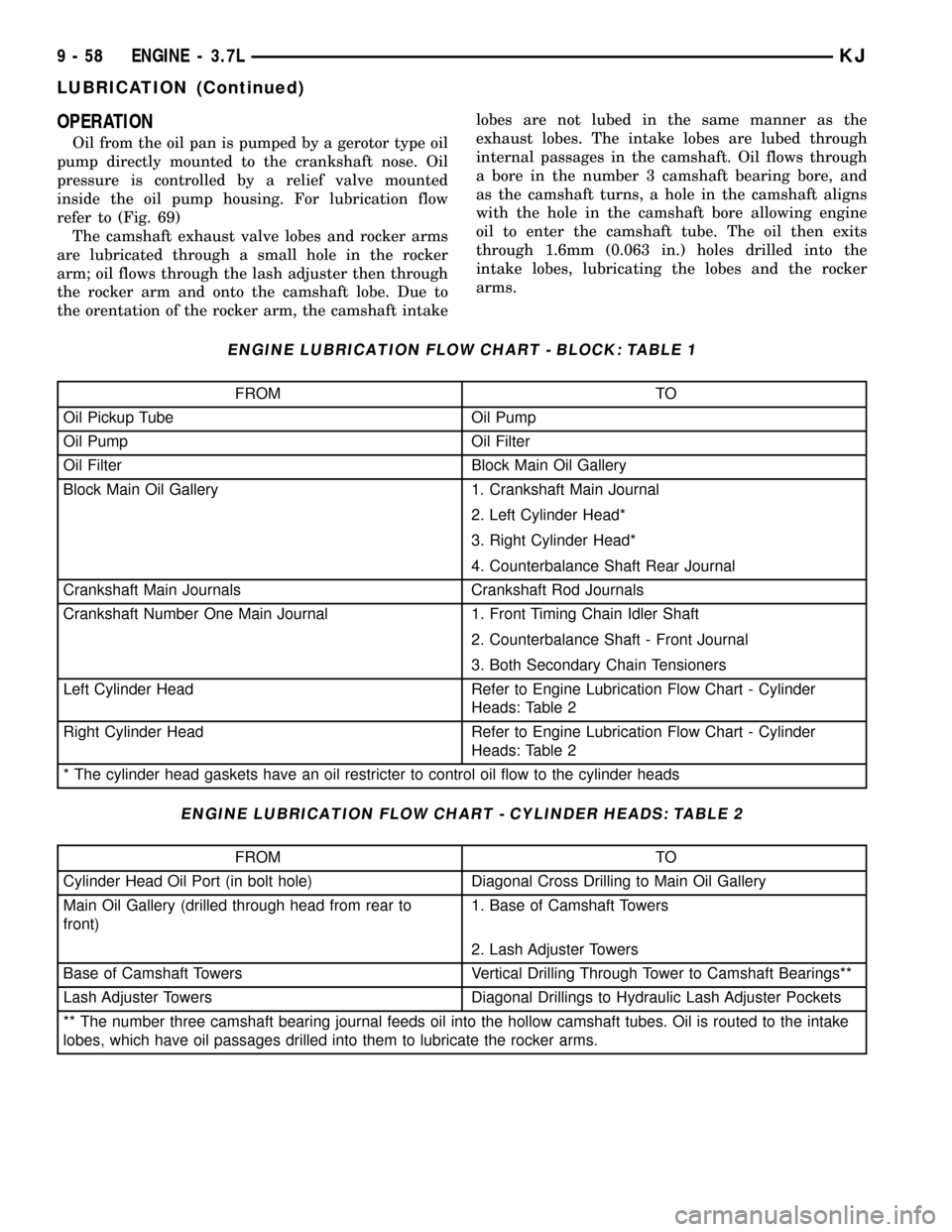
Oil from the oil pan is pumped by a gerotor type oil
pump directly mounted to the crankshaft nose. Oil
pressure is controlled by a relief valve mounted
inside the oil pump housing. For lubrication flow
refer to (Fig. 69)
The camshaft exhaust valve lobes and rocker arms
are lubricated through a small hole in the rocker
arm; oil flows through the lash adjuster then through
the rocker arm and onto the camshaft lobe. Due to
the orentation of the rocker arm, the camshaft intakelobes are not lubed in the same manner as the
exhaust lobes. The intake lobes are lubed through
internal passages in the camshaft. Oil flows through
a bore in the number 3 camshaft bearing bore, and
as the camshaft turns, a hole in the camshaft aligns
with the hole in the camshaft bore allowing engine
oil to enter the camshaft tube. The oil then exits
through 1.6mm (0.063 in.) holes drilled into the
intake lobes, lubricating the lobes and the rocker
arms.
ENGINE LUBRICATION FLOW CHART - BLOCK: TABLE 1
FROM TO
Oil Pickup Tube Oil Pump
Oil Pump Oil Filter
Oil Filter Block Main Oil Gallery
Block Main Oil Gallery 1. Crankshaft Main Journal
2. Left Cylinder Head*
3. Right Cylinder Head*
4. Counterbalance Shaft Rear Journal
Crankshaft Main Journals Crankshaft Rod Journals
Crankshaft Number One Main Journal 1. Front Timing Chain Idler Shaft
2. Counterbalance Shaft - Front Journal
3. Both Secondary Chain Tensioners
Left Cylinder Head Refer to Engine Lubrication Flow Chart - Cylinder
Heads: Table 2
Right Cylinder Head Refer to Engine Lubrication Flow Chart - Cylinder
Heads: Table 2
* The cylinder head gaskets have an oil restricter to control oil flow to the cylinder heads
ENGINE LUBRICATION FLOW CHART - CYLINDER HEADS: TABLE 2
FROM TO
Cylinder Head Oil Port (in bolt hole) Diagonal Cross Drilling to Main Oil Gallery
Main Oil Gallery (drilled through head from rear to
front)1. Base of Camshaft Towers
2. Lash Adjuster Towers
Base of Camshaft Towers Vertical Drilling Through Tower to Camshaft Bearings**
Lash Adjuster Towers Diagonal Drillings to Hydraulic Lash Adjuster Pockets
** The number three camshaft bearing journal feeds oil into the hollow camshaft tubes. Oil is routed to the intake
lobes, which have oil passages drilled into them to lubricate the rocker arms.
9 - 58 ENGINE - 3.7LKJ
LUBRICATION (Continued)
Page 1277 of 1803

ple viscosities such as 5W-30 or 10W-30 in the 3.7L
engines. These are specified with a dual SAE viscos-
ity grade which indicates the cold-to-hot temperature
viscosity range. Select an engine oil that is best
suited to your particular temperature range and vari-
ation (Fig. 71).
ENERGY CONSERVING OIL
An Energy Conserving type oil is recommended for
gasoline engines. The designation of ENERGY CON-
SERVING is located on the label of an engine oil con-
tainer.
CONTAINER IDENTIFICATION
Standard engine oil identification notations have
been adopted to aid in the proper selection of engine
oil. The identifying notations are located on the label
of engine oil plastic bottles and the top of engine oil
cans (Fig. 72).
OIL LEVEL INDICATOR (DIPSTICK)
The engine oil level indicator is located on the
right side of the the 3.7L engine.
CRANKCASE OIL LEVEL INSPECTION
CAUTION: Do not overfill crankcase with engine oil,
pressure loss or oil foaming can result.Inspect engine oil level approximately every 800
kilometers (500 miles). Unless the engine has exhib-
ited loss of oil pressure, run the engine for about five
minutes before checking oil level. Checking engine oil
level on a cold engine is not accurate.
To ensure proper lubrication of an engine, the
engine oil must be maintained at an acceptable level.
The acceptable levels are indicated between the ADD
and SAFE marks on the engine oil dipstick.
(1) Position vehicle on level surface.
(2) With engine OFF, allow approximately ten min-
utes for oil to settle to bottom of crankcase, remove
engine oil dipstick.
(3) Wipe dipstick clean.
(4) Install dipstick and verify it is seated in the
tube.
(5) Remove dipstick, with handle held above the
tip, take oil level reading.
(6) Add oil if level is below the SAFE ZONE on
dipstick.
ENGINE OIL CHANGE
Change engine oil at mileage and time intervals
described in Maintenance Schedules.
Run engine until achieving normal operating tem-
perature.
(1) Position the vehicle on a level surface and turn
engine off.
(2) Remove oil fill cap.
(3) Hoist and support vehicle on safety stands.
(4) Place a suitable drain pan under crankcase
drain.
(5) Remove drain plug from crankcase and allow
oil to drain into pan. Inspect drain plug threads for
stretching or other damage. Replace drain plug if
damaged.
(6) Install drain plug in crankcase.
(7) Remove oil filter (Refer to 9 - ENGINE/LUBRI-
CATION/OIL FILTER - REMOVAL).
(8) Install a new oil filter.
(9) Lower vehicle and fill crankcase with 5 quarts
of the specified type of engine oil described in this
section.
(10) Install oil fill cap.
(11) Start engine and inspect for leaks.
(12) Stop engine and inspect oil level.
USED ENGINE OIL DISPOSAL
Care should be exercised when disposing used
engine oil after it has been drained from a vehicle
engine. Refer to the WARNING at beginning of this
section.
Fig. 71 Temperature/Engine Oil Viscosity - 3.7L
Engine
Fig. 72 Engine Oil Container Standard Notations
9 - 62 ENGINE - 3.7LKJ
OIL (Continued)
Page 1278 of 1803
OIL FILTER
REMOVAL
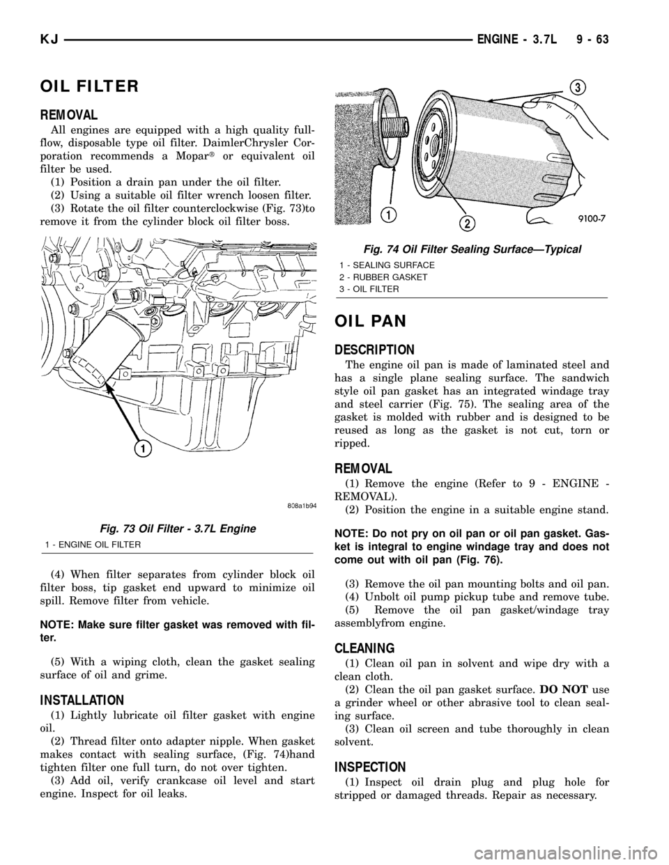
All engines are equipped with a high quality full-
flow, disposable type oil filter. DaimlerChrysler Cor-
poration recommends a Mopartor equivalent oil
filter be used.
(1) Position a drain pan under the oil filter.
(2) Using a suitable oil filter wrench loosen filter.
(3) Rotate the oil filter counterclockwise (Fig. 73)to
remove it from the cylinder block oil filter boss.
(4) When filter separates from cylinder block oil
filter boss, tip gasket end upward to minimize oil
spill. Remove filter from vehicle.
NOTE: Make sure filter gasket was removed with fil-
ter.
(5) With a wiping cloth, clean the gasket sealing
surface of oil and grime.
INSTALLATION
(1) Lightly lubricate oil filter gasket with engine
oil.
(2) Thread filter onto adapter nipple. When gasket
makes contact with sealing surface, (Fig. 74)hand
tighten filter one full turn, do not over tighten.
(3) Add oil, verify crankcase oil level and start
engine. Inspect for oil leaks.
OIL PAN
DESCRIPTION
The engine oil pan is made of laminated steel and
has a single plane sealing surface. The sandwich
style oil pan gasket has an integrated windage tray
and steel carrier (Fig. 75). The sealing area of the
gasket is molded with rubber and is designed to be
reused as long as the gasket is not cut, torn or
ripped.
REMOVAL
(1) Remove the engine (Refer to 9 - ENGINE -
REMOVAL).
(2) Position the engine in a suitable engine stand.
NOTE: Do not pry on oil pan or oil pan gasket. Gas-
ket is integral to engine windage tray and does not
come out with oil pan (Fig. 76).
(3) Remove the oil pan mounting bolts and oil pan.
(4) Unbolt oil pump pickup tube and remove tube.
(5) Remove the oil pan gasket/windage tray
assemblyfrom engine.
CLEANING
(1) Clean oil pan in solvent and wipe dry with a
clean cloth.
(2) Clean the oil pan gasket surface.DO NOTuse
a grinder wheel or other abrasive tool to clean seal-
ing surface.
(3) Clean oil screen and tube thoroughly in clean
solvent.
INSPECTION
(1) Inspect oil drain plug and plug hole for
stripped or damaged threads. Repair as necessary.
Fig. 73 Oil Filter - 3.7L Engine
1 - ENGINE OIL FILTER
Fig. 74 Oil Filter Sealing SurfaceÐTypical
1 - SEALING SURFACE
2 - RUBBER GASKET
3 - OIL FILTER
KJENGINE - 3.7L 9 - 63
Page 1286 of 1803

(1) Position the engine exhaust manifold and gas-
ket on the two studs located on the cylinder head.
Install conical washers and nuts on these studs.
(2) Install remaining conical washers. Starting at
the center arm and working outward, tighten the
bolts and nuts to 25 N´m (18 ft. lbs.) torque.
(3) Install the exhaust heat shields.
(4) Raise and support the vehicle.
CAUTION: Over tightening heat shield fasteners,
may cause shield to distort and/or crack.
(5) Assemble exhaust pipe to manifold and secure
with bolts, nuts and retainers. Tighten the bolts and
nuts to 34 N´m (25 ft. lbs.) torque.
LEFT EXHAUST MANIFOLD
CAUTION: If the studs came out with the nuts when
removing the engine exhaust manifold, install new
studs. Apply sealer on the coarse thread ends.
Water leaks may develop at the studs if this precau-
tion is not taken.
(1) Position the engine exhaust manifold and gas-
ket on the two studs located on the cylinder head.
Install conical washers and nuts on these studs.
(2) Install remaining conical washers. Starting at
the center arm and working outward, tighten the
bolts and nuts to 25 N´m (18 ft. lbs.) torque.
(3) Install the exhaust heat shields.
(4) Raise and support the vehicle.
CAUTION: Over tightening heat shield fasteners,
may cause shield to distort and/or crack.
(5) Assemble exhaust pipe to manifold and secure
with bolts, nuts and retainers. Tighten the bolts and
nuts to 34 N´m (25 ft. lbs.) torque.
VALVE TIMING
DESCRIPTION
The timing drive system has been designed to pro-
vide quiet performance and reliability to support a
non-free wheelingengine. Specifically the intake
valves are non-free wheeling and can be easily dam-
aged with forceful engine rotation if camshaft-to-
crankshaft timing is incorrect. The timing drive
system consists of a primary chain, two secondary
timing chain drives and a counterbalance shaft drive.
OPERATION
The primary timing chain is a single inverted tooth
chain type. The primary chain drives the large 40
tooth idler sprocket directly from a 20 tooth crank-shaft sprocket. Primary chain motion is controlled by
a pivoting leaf spring tensioner arm and a fixed
guide. The arm and the guide both use nylon plastic
wear faces for low friction and long wear. The pri-
mary chain receives oil splash lubrication from the
secondary chain drive and designed oil pump leak-
age. The idler sprocket assembly connects the pri-
mary chain drive, secondary chain drives, and the
counterbalance shaft. The idler sprocket assembly
consists of two integral 26 tooth sprockets a 40 tooth
sprocket and a helical gear that is press-fit to the
assembly. The spline joint for the 40 tooth sprocket is
a non ± serviceable press fit anti rattle type. A spiral
ring is installed on the outboard side of the fifty
tooth sprocket to prevent spline disengagement. The
idler sprocket assembly spins on a stationary idler
shaft. The idler shaft is a light press-fit into the cyl-
inder block. A large washer on the idler shaft bolt
and the rear flange of the idler shaft are used to con-
trol sprocket thrust movement. Pressurized oil is
routed through the center of the idler shaft to pro-
vide lubrication for the two bushings used in the
idler sprocket assembly.
There are two secondary drive chains, both are
roller type, one to drive the camshaft in each SOHC
cylinder head. There are no shaft speed changes in
the secondary chain drive system. Each secondary
chain drives a 26 tooth cam sprocket directly from
the 26 tooth sprocket on the idler sprocket assembly.
A fixed chain guide and a hydraulic oil damped ten-
sioner are used to maintain tension in each second-
ary chain system. The hydraulic tensioners for the
secondary chain systems are fed pressurized oil from
oil reservoir pockets in the block. Each tensioner
incorprates a controled leak path through a device
known as a vent disc located in the nose of the piston
to manage chain loads. Each tensioner also has a
mechanical ratchet system that limits chain slack if
the tensioner piston bleeds down after engine shut
down. The tensioner arms and guides also utilize
nylon wear faces for low friction and long wear. The
secondary timing chains receive lubrication from a
small orifice in the tensioners. This orifice is pro-
tected from clogging by a fine mesh screen which is
located on the back of the hydraulic tensioners.
STANDARD PROCEDURE
MEASURING TIMING CHAIN WEAR
NOTE: This procedure must be performed with the
timing chain cover removed.
(1) Remove the timing chain cover. Refer to Timing
Chain Cover in this section for procedure.
KJENGINE - 3.7L 9 - 71
EXHAUST MANIFOLD (Continued)
Page 1307 of 1803

(1) Inspect air cleaner, induction system and
intake manifold to insure system is dry and clear of
foreign material.
(2) Remove negative battery cable.
(3) Place a shop towel around the spark plugs
when removing them from the engine. This will catch
any fluid that may possibly be in the cylinder under
pressure.
(4) With all spark plugs removed, rotate engine
crankshaft using a breaker bar and socket.
(5) Identify the fluid in the cylinder(s) (i.e., cool-
ant, fuel, oil or other).
(6) Make sure all fluid has been removed from the
cylinders. Inspect engine for damage (i.e., connecting
rods, pistons, valves, etc.)
(7) Repair engine or components as necessary to
prevent this problem from re-occurring.
CAUTION: Squirt approximately one teaspoon of oil
into the cylinders, rotate engine to lubricate the cyl-
inder walls to prevent damage on restart.
(8) Install new spark plugs.
(9) Drain engine oil and remove oil filter.
(10) Install a new oil filter.
(11) Fill engine with specified amount of approved
oil.
(12) Connect negative battery cable.
(13) Start engine and check for any leaks.
STANDARD PROCEDURE - FORM-IN-PLACE
GASKETS AND SEALERS
There are numerous places where form-in-place
gaskets are used on the engine. Care must be taken
when applying form-in-place gaskets to assure
obtaining the desired results.Do not use form-in-
place gasket material unless specified.Bead size,
continuity, and location are of great importance. Too
thin a bead can result in leakage while too much can
result in spill-over which can break off and obstruct
fluid feed lines. A continuous bead of the proper
width is essential to obtain a leak-free gasket.
There are numerous types of form-in-place gasket
materials that are used in the engine area. Mopart
Engine RTV GEN II, MopartATF-RTV, and Mopart
Gasket Maker gasket materials, each have different
properties and can not be used in place of the other.
MOPARtENGINE RTV GEN IIis used to seal
components exposed to engine oil. This material is a
specially designed black silicone rubber RTV that
retains adhesion and sealing properties when
exposed to engine oil. Moisture in the air causes the
material to cure. This material is available in three
ounce tubes and has a shelf life of one year. After one
year this material will not properly cure. Alwaysinspect the package for the expiration date before
use.
MOPARtATF RTVis a specifically designed
black silicone rubber RTV that retains adhesion and
sealing properties to seal components exposed to
automatic transmission fluid, engine coolants, and
moisture. This material is available in three ounce
tubes and has a shelf life of one year. After one year
this material will not properly cure. Always inspect
the package for the expiration date before use.
MOPARtGASKET MAKERis an anaerobic type
gasket material. The material cures in the absence of
air when squeezed between two metallic surfaces. It
will not cure if left in the uncovered tube. The
anaerobic material is for use between two machined
surfaces. Do not use on flexible metal flanges.
MOPARtBED PLATE SEALANTis a unique
(green-in-color) anaerobic type gasket material that
is specially made to seal the area between the bed-
plate and cylinder block without disturbing the bear-
ing clearance or alignment of these components. The
material cures slowly in the absence of air when
torqued between two metallic surfaces, and will rap-
idly cure when heat is applied.
MOPARtGASKET SEALANTis a slow drying,
permanently soft sealer. This material is recom-
mended for sealing threaded fittings and gaskets
against leakage of oil and coolant. Can be used on
threaded and machined parts under all tempera-
tures. This material is used on engines with multi-
layer steel (MLS) cylinder head gaskets. This
material also will prevent corrosion. MopartGasket
Sealant is available in a 13 oz. aerosol can or 4oz./16
oz. can w/applicator.
SEALER APPLICATION
MopartGasket Maker material should be applied
sparingly 1 mm (0.040 in.) diameter or less of sealant
to one gasket surface. Be certain the material sur-
rounds each mounting hole. Excess material can eas-
ily be wiped off. Components should be torqued in
place within 15 minutes. The use of a locating dowel
is recommended during assembly to prevent smear-
ing material off the location.
MopartEngine RTV GEN II or ATF RTV gasket
material should be applied in a continuous bead
approximately 3 mm (0.120 in.) in diameter. All
mounting holes must be circled. For corner sealing, a
3.17 or 6.35 mm (1/8 or 1/4 in.) drop is placed in the
center of the gasket contact area. Uncured sealant
may be removed with a shop towel. Components
should be torqued in place while the sealant is still
wet to the touch (within 10 minutes). The usage of a
locating dowel is recommended during assembly to
prevent smearing material off the location.
9s - 10 ENGINEKJ
ENGINE - 2.4L (Continued)
Page 1343 of 1803
LUBRICATION
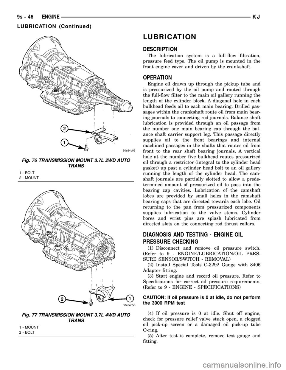
DESCRIPTION
The lubrication system is a full-flow filtration,
pressure feed type. The oil pump is mounted in the
front engine cover and driven by the crankshaft.
OPERATION
Engine oil drawn up through the pickup tube and
is pressurized by the oil pump and routed through
the full-flow filter to the main oil gallery running the
length of the cylinder block. A diagonal hole in each
bulkhead feeds oil to each main bearing. Drilled pas-
sages within the crankshaft route oil from main bear-
ing journals to connecting rod journals. Balance shaft
lubrication is provided through an oil passage from
the number one main bearing cap through the bal-
ance shaft carrier support leg. This passage directly
supplies oil to the front bearings and internal
machined passages in the shafts that routes oil from
front to the rear shaft bearing journals. A vertical
hole at the number five bulkhead routes pressurized
oil through a restrictor (integral to the cylinder head
gasket) up past a cylinder head bolt to an oil gallery
running the length of the cylinder head. The cam-
shaft journals are partially slotted to allow a prede-
termined amount of pressurized oil to pass into the
bearing cap cavities. Lubrication of the camshaft
lobes are provided by small holes in the camshaft
bearing caps that are directed towards each lobe. Oil
returning to the pan from pressurized components
supplies lubrication to the valve stems. Cylinder
bores and wrist pins are splash lubricated from
directed slots on the connecting rod thrust collars.
DIAGNOSIS AND TESTING - ENGINE OIL
PRESSURE CHECKING
(1) Disconnect and remove oil pressure switch.
(Refer to 9 - ENGINE/LUBRICATION/OIL PRES-
SURE SENSOR/SWITCH - REMOVAL)
(2) Install Special Tools C-3292 Gauge with 8406
Adaptor fitting.
(3) Start engine and record oil pressure. Refer to
Specifications for correct oil pressure requirements.
(Refer to 9 - ENGINE - SPECIFICATIONS)
CAUTION: If oil pressure is 0 at idle, do not perform
the 3000 RPM test
(4) If oil pressure is 0 at idle. Shut off engine,
check for pressure relief valve stuck open, a clogged
oil pick-up screen or a damaged oil pick-up tube
O-ring.
(5) After test is complete, remove test gauge and
fitting.
Fig. 76 TRANSMISSION MOUNT 3.7L 2WD AUTO
TRANS
1 - BOLT
2 - MOUNT
Fig. 77 TRANSMISSION MOUNT 3.7L 4WD AUTO
TRANS
1 - MOUNT
2 - BOLT
9s - 46 ENGINEKJ
LUBRICATION (Continued)
Page 1344 of 1803
(6) Install oil pressure switch and connector. (Refer
to 9 - ENGINE/LUBRICATION/OIL PRESSURE
SENSOR/SWITCH - INSTALLATION)
OIL
STANDARD PROCEDURE
ENGINE OIL LEVEL CHECK
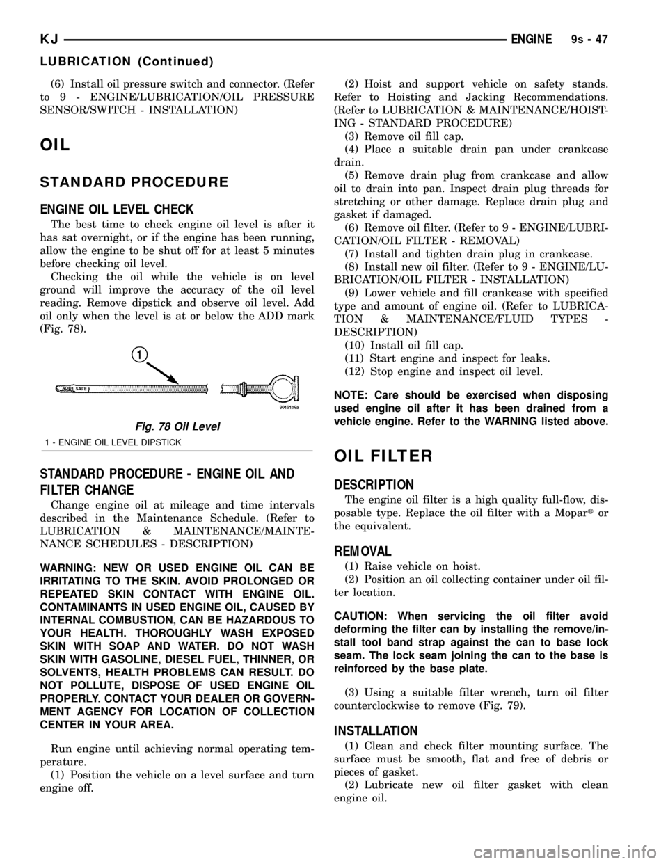
The best time to check engine oil level is after it
has sat overnight, or if the engine has been running,
allow the engine to be shut off for at least 5 minutes
before checking oil level.
Checking the oil while the vehicle is on level
ground will improve the accuracy of the oil level
reading. Remove dipstick and observe oil level. Add
oil only when the level is at or below the ADD mark
(Fig. 78).
STANDARD PROCEDURE - ENGINE OIL AND
FILTER CHANGE
Change engine oil at mileage and time intervals
described in the Maintenance Schedule. (Refer to
LUBRICATION & MAINTENANCE/MAINTE-
NANCE SCHEDULES - DESCRIPTION)
WARNING: NEW OR USED ENGINE OIL CAN BE
IRRITATING TO THE SKIN. AVOID PROLONGED OR
REPEATED SKIN CONTACT WITH ENGINE OIL.
CONTAMINANTS IN USED ENGINE OIL, CAUSED BY
INTERNAL COMBUSTION, CAN BE HAZARDOUS TO
YOUR HEALTH. THOROUGHLY WASH EXPOSED
SKIN WITH SOAP AND WATER. DO NOT WASH
SKIN WITH GASOLINE, DIESEL FUEL, THINNER, OR
SOLVENTS, HEALTH PROBLEMS CAN RESULT. DO
NOT POLLUTE, DISPOSE OF USED ENGINE OIL
PROPERLY. CONTACT YOUR DEALER OR GOVERN-
MENT AGENCY FOR LOCATION OF COLLECTION
CENTER IN YOUR AREA.
Run engine until achieving normal operating tem-
perature.
(1) Position the vehicle on a level surface and turn
engine off.(2) Hoist and support vehicle on safety stands.
Refer to Hoisting and Jacking Recommendations.
(Refer to LUBRICATION & MAINTENANCE/HOIST-
ING - STANDARD PROCEDURE)
(3) Remove oil fill cap.
(4) Place a suitable drain pan under crankcase
drain.
(5) Remove drain plug from crankcase and allow
oil to drain into pan. Inspect drain plug threads for
stretching or other damage. Replace drain plug and
gasket if damaged.
(6) Remove oil filter. (Refer to 9 - ENGINE/LUBRI-
CATION/OIL FILTER - REMOVAL)
(7) Install and tighten drain plug in crankcase.
(8) Install new oil filter. (Refer to 9 - ENGINE/LU-
BRICATION/OIL FILTER - INSTALLATION)
(9) Lower vehicle and fill crankcase with specified
type and amount of engine oil. (Refer to LUBRICA-
TION & MAINTENANCE/FLUID TYPES -
DESCRIPTION)
(10) Install oil fill cap.
(11) Start engine and inspect for leaks.
(12) Stop engine and inspect oil level.
NOTE: Care should be exercised when disposing
used engine oil after it has been drained from a
vehicle engine. Refer to the WARNING listed above.
OIL FILTER
DESCRIPTION
The engine oil filter is a high quality full-flow, dis-
posable type. Replace the oil filter with a Mopartor
the equivalent.
REMOVAL
(1) Raise vehicle on hoist.
(2) Position an oil collecting container under oil fil-
ter location.
CAUTION: When servicing the oil filter avoid
deforming the filter can by installing the remove/in-
stall tool band strap against the can to base lock
seam. The lock seam joining the can to the base is
reinforced by the base plate.
(3) Using a suitable filter wrench, turn oil filter
counterclockwise to remove (Fig. 79).
INSTALLATION
(1) Clean and check filter mounting surface. The
surface must be smooth, flat and free of debris or
pieces of gasket.
(2) Lubricate new oil filter gasket with clean
engine oil.
Fig. 78 Oil Level
1 - ENGINE OIL LEVEL DIPSTICK
KJENGINE9s-47
LUBRICATION (Continued)
Page 1423 of 1803
ronment that they operate in, that keep them from
being interchangeable.
Maintaining correct sensor temperature at all
times allows the system to enter into closed loop
operation sooner. Also, it allows the system to remain
in closed loop operation during periods of extended
idle.
In Closed Loop operation, the PCM monitors cer-
tain O2 sensor input(s) along with other inputs, and
adjusts the injector pulse width accordingly. During
Open Loop operation, the PCM ignores the O2 sensor
input. The PCM adjusts injector pulse width based
on preprogrammed (fixed) values and inputs from
other sensors.
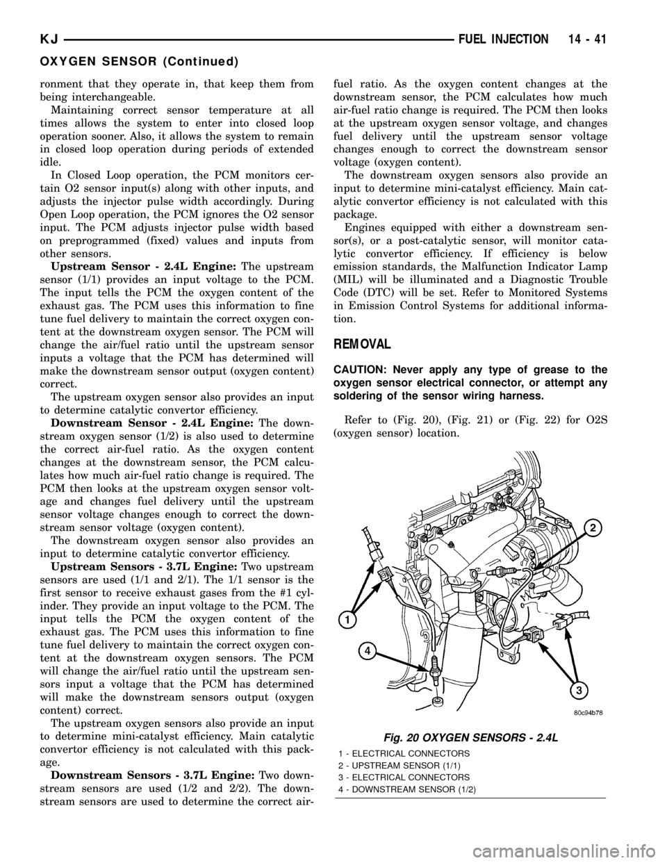
Upstream Sensor - 2.4L Engine:The upstream
sensor (1/1) provides an input voltage to the PCM.
The input tells the PCM the oxygen content of the
exhaust gas. The PCM uses this information to fine
tune fuel delivery to maintain the correct oxygen con-
tent at the downstream oxygen sensor. The PCM will
change the air/fuel ratio until the upstream sensor
inputs a voltage that the PCM has determined will
make the downstream sensor output (oxygen content)
correct.
The upstream oxygen sensor also provides an input
to determine catalytic convertor efficiency.
Downstream Sensor - 2.4L Engine:The down-
stream oxygen sensor (1/2) is also used to determine
the correct air-fuel ratio. As the oxygen content
changes at the downstream sensor, the PCM calcu-
lates how much air-fuel ratio change is required. The
PCM then looks at the upstream oxygen sensor volt-
age and changes fuel delivery until the upstream
sensor voltage changes enough to correct the down-
stream sensor voltage (oxygen content).
The downstream oxygen sensor also provides an
input to determine catalytic convertor efficiency.
Upstream Sensors - 3.7L Engine:Two upstream
sensors are used (1/1 and 2/1). The 1/1 sensor is the
first sensor to receive exhaust gases from the #1 cyl-
inder. They provide an input voltage to the PCM. The
input tells the PCM the oxygen content of the
exhaust gas. The PCM uses this information to fine
tune fuel delivery to maintain the correct oxygen con-
tent at the downstream oxygen sensors. The PCM
will change the air/fuel ratio until the upstream sen-
sors input a voltage that the PCM has determined
will make the downstream sensors output (oxygen
content) correct.
The upstream oxygen sensors also provide an input
to determine mini-catalyst efficiency. Main catalytic
convertor efficiency is not calculated with this pack-
age.
Downstream Sensors - 3.7L Engine:Two down-
stream sensors are used (1/2 and 2/2). The down-
stream sensors are used to determine the correct air-fuel ratio. As the oxygen content changes at the
downstream sensor, the PCM calculates how much
air-fuel ratio change is required. The PCM then looks
at the upstream oxygen sensor voltage, and changes
fuel delivery until the upstream sensor voltage
changes enough to correct the downstream sensor
voltage (oxygen content).
The downstream oxygen sensors also provide an
input to determine mini-catalyst efficiency. Main cat-
alytic convertor efficiency is not calculated with this
package.
Engines equipped with either a downstream sen-
sor(s), or a post-catalytic sensor, will monitor cata-
lytic convertor efficiency. If efficiency is below
emission standards, the Malfunction Indicator Lamp
(MIL) will be illuminated and a Diagnostic Trouble
Code (DTC) will be set. Refer to Monitored Systems
in Emission Control Systems for additional informa-
tion.
REMOVAL
CAUTION: Never apply any type of grease to the
oxygen sensor electrical connector, or attempt any
soldering of the sensor wiring harness.
Refer to (Fig. 20), (Fig. 21) or (Fig. 22) for O2S
(oxygen sensor) location.
Fig. 20 OXYGEN SENSORS - 2.4L
1 - ELECTRICAL CONNECTORS
2 - UPSTREAM SENSOR (1/1)
3 - ELECTRICAL CONNECTORS
4 - DOWNSTREAM SENSOR (1/2)
KJFUEL INJECTION 14 - 41
OXYGEN SENSOR (Continued)