2002 JEEP LIBERTY Regulator
[x] Cancel search: RegulatorPage 1400 of 1803
(17) When LCS adapter test leads are attached
into relay cavities, fuel pumpwill be activated.
Determine fuel pump amperage on DRB screen.
Amperage should be below 10.0 amps. If amperage is
below 10.0 amps, and specifications for the Fuel
Pump Pressure, Fuel Pump Capacity and Fuel Pres-
sure Leak Down tests were met, the fuel pump mod-
ule is OK.
(18) If amperage is more than 10.0 amps, replace
fuel pump module assembly. The electric fuel pump
is not serviced separately.
(19) Disconnect test leads from relay cavities
immediately after testing.
FUEL PUMP MODULE
DESCRIPTION
The fuel pump module assembly is located in the
fuel tank (Fig. 1). The assembly is divided into 2±sec-
tions, upper and lower. The lower section is locked to
the bottom of the fuel tank. The complete assembly
contains the following components:
²A fuel pressure regulator
²A separate fuel pick-up, or inlet filter
²An electric fuel pump
²A lockring to retain upper section of pump mod-
ule to tank
²A rollover valve
²A vent fitting for ORVR system
²A soft gasket between tank flange and module
²A fuel gauge sending unit (fuel level sensor)
²Two fuel line connections (supply and return)
The fuel gauge sending unit may be serviced sepa-
rately. If the electrical fuel pump, primary inlet filter
or fuel pressure regulator require service, the lower
section of the fuel pump module must be replaced.
OPERATION
Refer to Fuel Pump, Inlet Filter, Fuel Pressure
Regulator and Fuel Gauge Sending Unit.
REMOVAL
The fuel pump module is divided into 2 sections,
upper and lower. To service the check (control) valve,
replace only the upper section. To service the fuel
gauge sending unit, remove the upper section. To ser-
vice the electric fuel pump, fuel pressure regulator or
primary inlet filter, remove both sections and replace
lower section.
Fuel tank removal will not be necessary for
fuel pump module removal. Access is from rear
cargo area.
(1) Four cargo holdown clamps are located inside
the vehicle on the floor of the rear cargo area.Remove the 2 rearward mounted clamps by drilling
out the clamp rivets.
(2) Fold carpeting forward to gain access to fuel
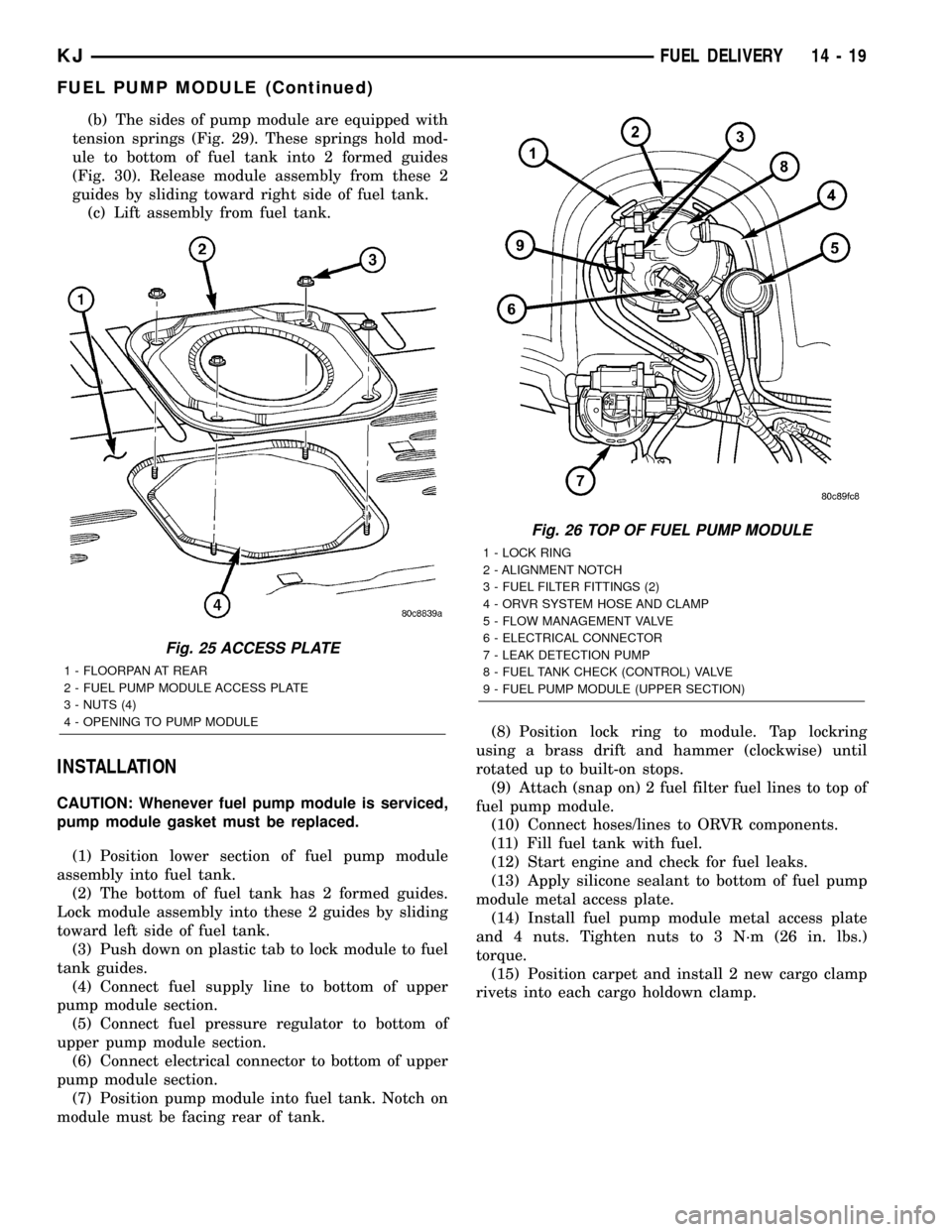
pump module access plate (Fig. 25).
(3) Remove 4 fuel pump module access plate nuts
(Fig. 25).
(4) While applying heat from a heat gun, carefully
pry up fuel pump module access plate. Take care not
to bend plate.
(5) Thoroughly clean area around top of pump
module to prevent contaminants from entering fuel
tank or fuel lines.
WARNING: THE FUEL SYSTEM IS UNDER A CON-
STANT PRESSURE EVEN WITH ENGINE OFF.
BEFORE SERVICING THE FUEL PUMP MODULE,
FUEL SYSTEM PRESSURE MUST BE RELEASED.
(6) Release fuel system pressure. Refer to Fuel
System Pressure Release procedure.
(7) Disconnect 2 fuel lines at fuel pump module
(Fig. 26) by pressing on 2 buttons at sides of fitting.
(8) Disconnect electrical connector (Fig. 26) at top
of fuel pump module by sliding red colored tab first
to unlock, and push grey colored tab down for
removal.
(9) Disconnect ORVR hose clamp and hose (Fig.
26) at pump module fitting.
(10) Remove module lockring (Fig. 26) using a
brass drift and hammer (counter-clockwise).
(11) Carefully lift upper section of pump module
(Fig. 26) from fuel tank exposing connections(lift
upper section from tank very slowly until rub-
ber gasket can be retained. If not, gasket will
fall into fuel tank.)
(a) Disconnect electrical connector (Fig. 27) at
bottom of upper pump module section.
(b) Disconnect fuel pressure regulator (Fig. 27)
at bottom of upper pump module section. Press on
2 locking tabs.
(c) Disconnect fuel return line (Fig. 27) at bot-
tom of upper pump module section. Press on 2
locking tabs.
(d) Remove upper section of pump module (Fig.
28) from fuel tank.
(12) Using an approved gas holding tank, drain
fuel tank through pump module opening.If check
(control) valve, or, only upper section of pump
module is being serviced, tank draining is not
necessary. If any other fuel pump module com-
ponent is being serviced, the tank must be com-
pletely drained to the bottom.
(13) To remove lower section of pump module from
fuel tank:
(a) Using finger pressure, push on plastic
release tab (Fig. 29) while sliding lock tab upward.
14 - 18 FUEL DELIVERYKJ
FUEL PUMP (Continued)
Page 1401 of 1803
(b) The sides of pump module are equipped with
tension springs (Fig. 29). These springs hold mod-
ule to bottom of fuel tank into 2 formed guides
(Fig. 30). Release module assembly from these 2
guides by sliding toward right side of fuel tank.
(c) Lift assembly from fuel tank.
INSTALLATION
CAUTION: Whenever fuel pump module is serviced,
pump module gasket must be replaced.
(1) Position lower section of fuel pump module
assembly into fuel tank.
(2) The bottom of fuel tank has 2 formed guides.
Lock module assembly into these 2 guides by sliding
toward left side of fuel tank.
(3) Push down on plastic tab to lock module to fuel
tank guides.
(4) Connect fuel supply line to bottom of upper
pump module section.
(5) Connect fuel pressure regulator to bottom of
upper pump module section.
(6) Connect electrical connector to bottom of upper
pump module section.
(7) Position pump module into fuel tank. Notch on
module must be facing rear of tank.(8) Position lock ring to module. Tap lockring
using a brass drift and hammer (clockwise) until
rotated up to built-on stops.
(9) Attach (snap on) 2 fuel filter fuel lines to top of
fuel pump module.
(10) Connect hoses/lines to ORVR components.
(11) Fill fuel tank with fuel.
(12) Start engine and check for fuel leaks.
(13) Apply silicone sealant to bottom of fuel pump
module metal access plate.
(14) Install fuel pump module metal access plate
and 4 nuts. Tighten nuts to 3 N´m (26 in. lbs.)
torque.
(15) Position carpet and install 2 new cargo clamp
rivets into each cargo holdown clamp.
Fig. 25 ACCESS PLATE
1 - FLOORPAN AT REAR
2 - FUEL PUMP MODULE ACCESS PLATE
3 - NUTS (4)
4 - OPENING TO PUMP MODULE
Fig. 26 TOP OF FUEL PUMP MODULE
1 - LOCK RING
2 - ALIGNMENT NOTCH
3 - FUEL FILTER FITTINGS (2)
4 - ORVR SYSTEM HOSE AND CLAMP
5 - FLOW MANAGEMENT VALVE
6 - ELECTRICAL CONNECTOR
7 - LEAK DETECTION PUMP
8 - FUEL TANK CHECK (CONTROL) VALVE
9 - FUEL PUMP MODULE (UPPER SECTION)
KJFUEL DELIVERY 14 - 19
FUEL PUMP MODULE (Continued)
Page 1402 of 1803
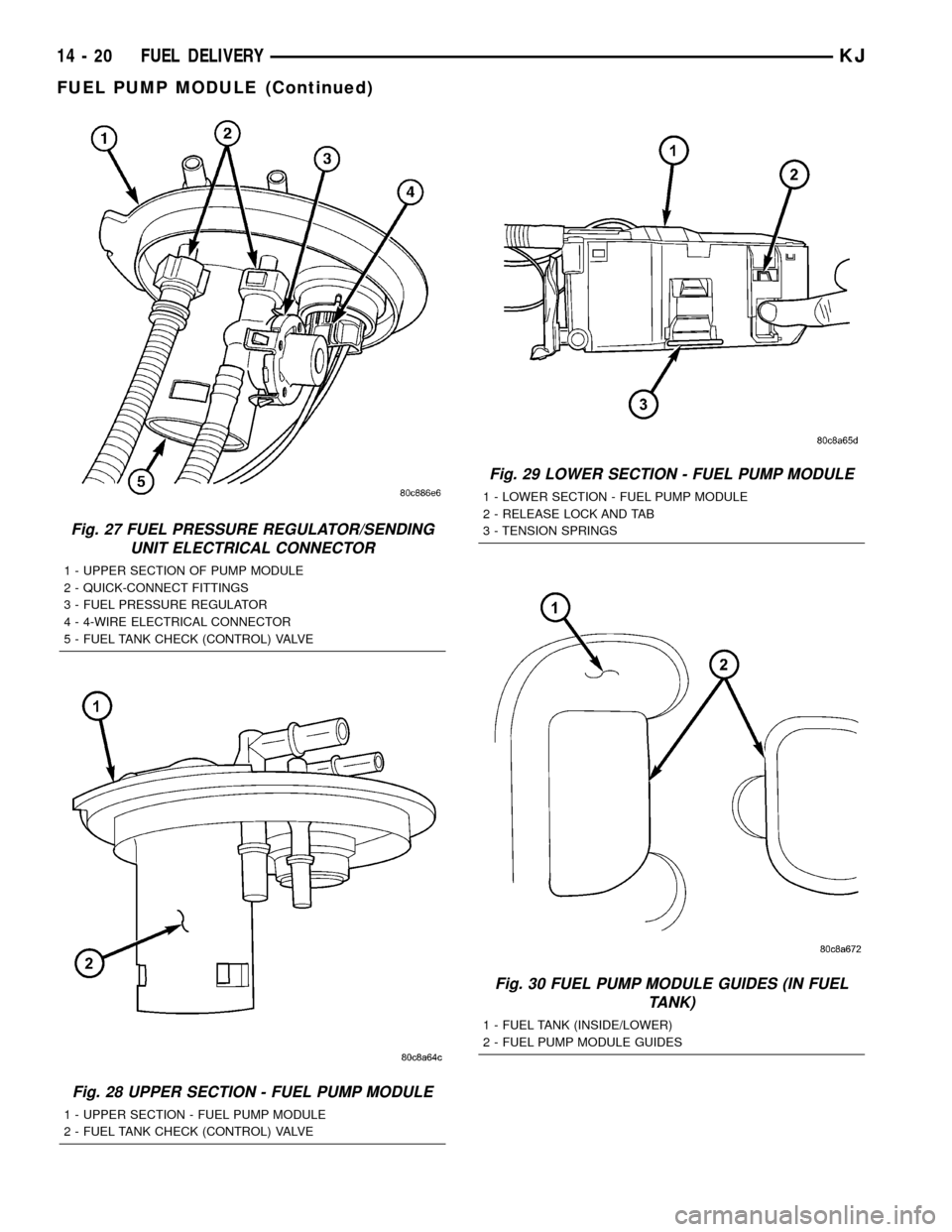
Fig. 27 FUEL PRESSURE REGULATOR/SENDING
UNIT ELECTRICAL CONNECTOR
1 - UPPER SECTION OF PUMP MODULE
2 - QUICK-CONNECT FITTINGS
3 - FUEL PRESSURE REGULATOR
4 - 4-WIRE ELECTRICAL CONNECTOR
5 - FUEL TANK CHECK (CONTROL) VALVE
Fig. 28 UPPER SECTION - FUEL PUMP MODULE
1 - UPPER SECTION - FUEL PUMP MODULE
2 - FUEL TANK CHECK (CONTROL) VALVE
Fig. 29 LOWER SECTION - FUEL PUMP MODULE
1 - LOWER SECTION - FUEL PUMP MODULE
2 - RELEASE LOCK AND TAB
3 - TENSION SPRINGS
Fig. 30 FUEL PUMP MODULE GUIDES (IN FUEL
TANK)
1 - FUEL TANK (INSIDE/LOWER)
2 - FUEL PUMP MODULE GUIDES
14 - 20 FUEL DELIVERYKJ
FUEL PUMP MODULE (Continued)
Page 1404 of 1803
of the firing of the fuel injectors. It isnot usedas a
fuel pressure regulator. The fuel pressure regulator is
not mountedto the fuel rail on any engine. It is
located on the fuel tank mounted fuel pump module.
Refer to Fuel Pressure Regulator for additional infor-
mation.
The fuel rail is not repairable.
A quick-connect fitting with a safety latch is used
to attach the fuel line to the fuel rail.
3.7L
High pressure fuel from the fuel pump is routed to
the fuel rail. The fuel rail then supplies the neces-
sary fuel to each individual fuel injector.
A quick-connect fitting with a safety latch is used
to attach the fuel line to the fuel rail.
The fuel rail is not repairable.
REMOVAL
2.4L
WARNING: THE FUEL SYSTEM IS UNDER CON-
STANT PRESSURE EVEN WITH ENGINE OFF.
BEFORE SERVICING FUEL RAIL, FUEL SYSTEM
PRESSURE MUST BE RELEASED.
The fuel rail can be removed without removing the
intake manifold if the following procedures are fol-
lowed.(1) Remove fuel tank filler tube cap.
(2) Perform Fuel System Pressure Release Proce-
dure.
(3) Remove negative battery cable at battery.
(4) Remove air duct at throttle body.
(5) Disconnect fuel line latch clip and fuel line at
fuel rail. A special tool will be necessary for fuel line
disconnection. Refer to Quick-Connect Fittings.
(6) Remove necessary vacuum lines at throttle
body.
(7) Drain engine coolant and remove thermostat
and thermostat housing.
(8) Remove PCV hose and valve at valve cover.
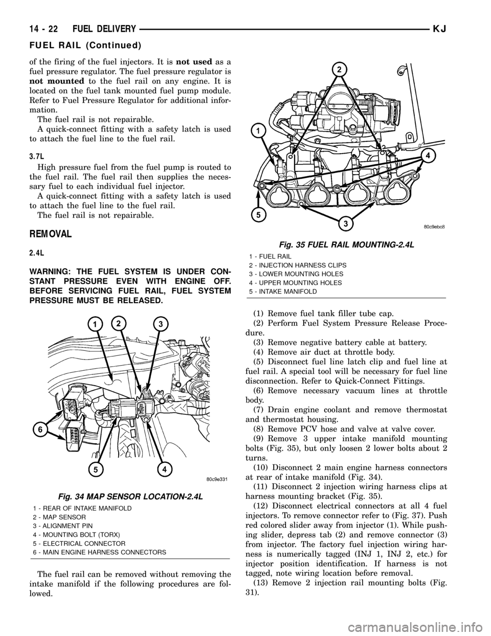
(9) Remove 3 upper intake manifold mounting
bolts (Fig. 35), but only loosen 2 lower bolts about 2
turns.
(10) Disconnect 2 main engine harness connectors
at rear of intake manifold (Fig. 34).
(11) Disconnect 2 injection wiring harness clips at
harness mounting bracket (Fig. 35).
(12) Disconnect electrical connectors at all 4 fuel
injectors. To remove connector refer to (Fig. 37). Push
red colored slider away from injector (1). While push-
ing slider, depress tab (2) and remove connector (3)
from injector. The factory fuel injection wiring har-
ness is numerically tagged (INJ 1, INJ 2, etc.) for
injector position identification. If harness is not
tagged, note wiring location before removal.
(13) Remove 2 injection rail mounting bolts (Fig.
31).
Fig. 34 MAP SENSOR LOCATION-2.4L
1 - REAR OF INTAKE MANIFOLD
2 - MAP SENSOR
3 - ALIGNMENT PIN
4 - MOUNTING BOLT (TORX)
5 - ELECTRICAL CONNECTOR
6 - MAIN ENGINE HARNESS CONNECTORS
Fig. 35 FUEL RAIL MOUNTING-2.4L
1 - FUEL RAIL
2 - INJECTION HARNESS CLIPS
3 - LOWER MOUNTING HOLES
4 - UPPER MOUNTING HOLES
5 - INTAKE MANIFOLD
14 - 22 FUEL DELIVERYKJ
FUEL RAIL (Continued)
Page 1469 of 1803
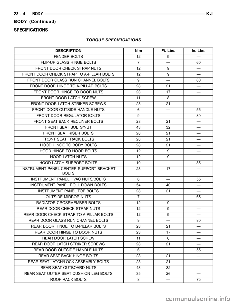
SPECIFICATIONS
TORQUE SPECIFICATIONS
DESCRIPTION N´m Ft. Lbs. In. Lbs.
FENDER BOLTS 12 9 Ð
FLIP-UP GLASS HINGE BOLTS 7 Ð 60
FRONT DOOR CHECK STRAP NUTS 12 9 Ð
FRONT DOOR CHECK STRAP TO A-PILLAR BOLTS 12 9 Ð
FRONT DOOR GLASS RUN CHANNEL BOLTS 9 Ð 80
FRONT DOOR HINGE TO A-PILLAR BOLTS 28 21 Ð
FRONT DOOR HINGE TO DOOR NUTS 23 17 Ð
FRONT DOOR LATCH SCREW 11 8 Ð
FRONT DOOR LATCH STRIKER SCREWS 28 21 Ð
FRONT DOOR OUTSIDE HANDLE NUTS 6 Ð 55
FRONT DOOR REGULATOR BOLTS 9 Ð 80
FRONT SEAT BACK RECLINER BOLTS 28 21 Ð
FRONT SEAT BOLTS/NUT 43 32 Ð
FRONT SEAT RISER BOLTS 28 21 Ð
FRONT SEAT TRACK BOLTS 28 21 Ð
HOOD HINGE TO BODY BOLTS 28 21 Ð
HOOD HINGE TO HOOD BOLTS 12 9 Ð
HOOD LATCH NUTS 12 9 Ð
HOOD LATCH SUPPORT BOLTS 10 Ð 85
INSTRUMENT PANEL CENTER SUPPORT BRACKET
BOLTS23 17 Ð
INSTRUMENT PANEL HVAC NUTS/BOLTS 6 Ð 55
INSTRUMENT PANEL ROLL DOWN BOLTS 54 40 Ð
INSTRUMENT PANEL TOP BOLTS 28 21 Ð
OUTSIDE MIRROR NUTS 7 Ð 65
RADIATOR CROSSMEMBER BOLTS 12 9 Ð
REAR DOOR CHECK STRAP NUTS 12 9 Ð
REAR DOOR CHECK STRAP TO A-PILLAR BOLTS 12 9 Ð
REAR DOOR GLASS RUN CHANNEL BOLTS 9 Ð 80
REAR DOOR HINGE TO B-PILLAR BOLTS 28 21 Ð
REAR DOOR HINGE TO DOOR NUTS 23 17 Ð
REAR DOOR LATCH SCREW 11 8 Ð
REAR DOOR LATCH STRIKER SCREWS 28 21 Ð
REAR DOOR OUTSIDE HANDLE NUTS 6 Ð 55
REAR SEAT BACK HINGE BOLTS 28 21 Ð
REAR SEAT LATCH/LOCK ASSEMBLY BOLTS 28 21 Ð
REAR SEAT OUTBOARD NUTS 43 32 Ð
REAR SEAT OUTER SEAT CUSHION LEG BOLTS 35 26 Ð
ROOF RACK BOLTS 8 Ð 75
23 - 4 BODYKJ
BODY (Continued)
Page 1586 of 1803
DOOR - FRONT
TABLE OF CONTENTS
page page
CHECK STRAP
REMOVAL............................121
INSTALLATION........................121
DOOR
REMOVAL............................122
INSTALLATION........................122
DOOR GLASS
REMOVAL............................122
INSTALLATION........................122
EXTERIOR HANDLE
REMOVAL............................123
INSTALLATION........................123
GLASS RUN CHANNEL
REMOVAL............................123
INSTALLATION........................123
HINGE
REMOVAL............................123
INSTALLATION........................123
LATCH
REMOVAL............................124
INSTALLATION........................124ADJUSTMENTS
ADJUSTMENT.......................124
LATCH STRIKER
REMOVAL............................124
INSTALLATION........................124
LOCK CYLINDER
REMOVAL............................125
INSTALLATION........................125
TRIM PANEL
REMOVAL............................125
INSTALLATION........................126
WATERDAM
REMOVAL............................126
INSTALLATION........................126
WINDOW REGULATOR - MANUAL
REMOVAL............................126
INSTALLATION........................126
WINDOW REGULATOR - ELECTRIC
REMOVAL............................126
INSTALLATION........................126
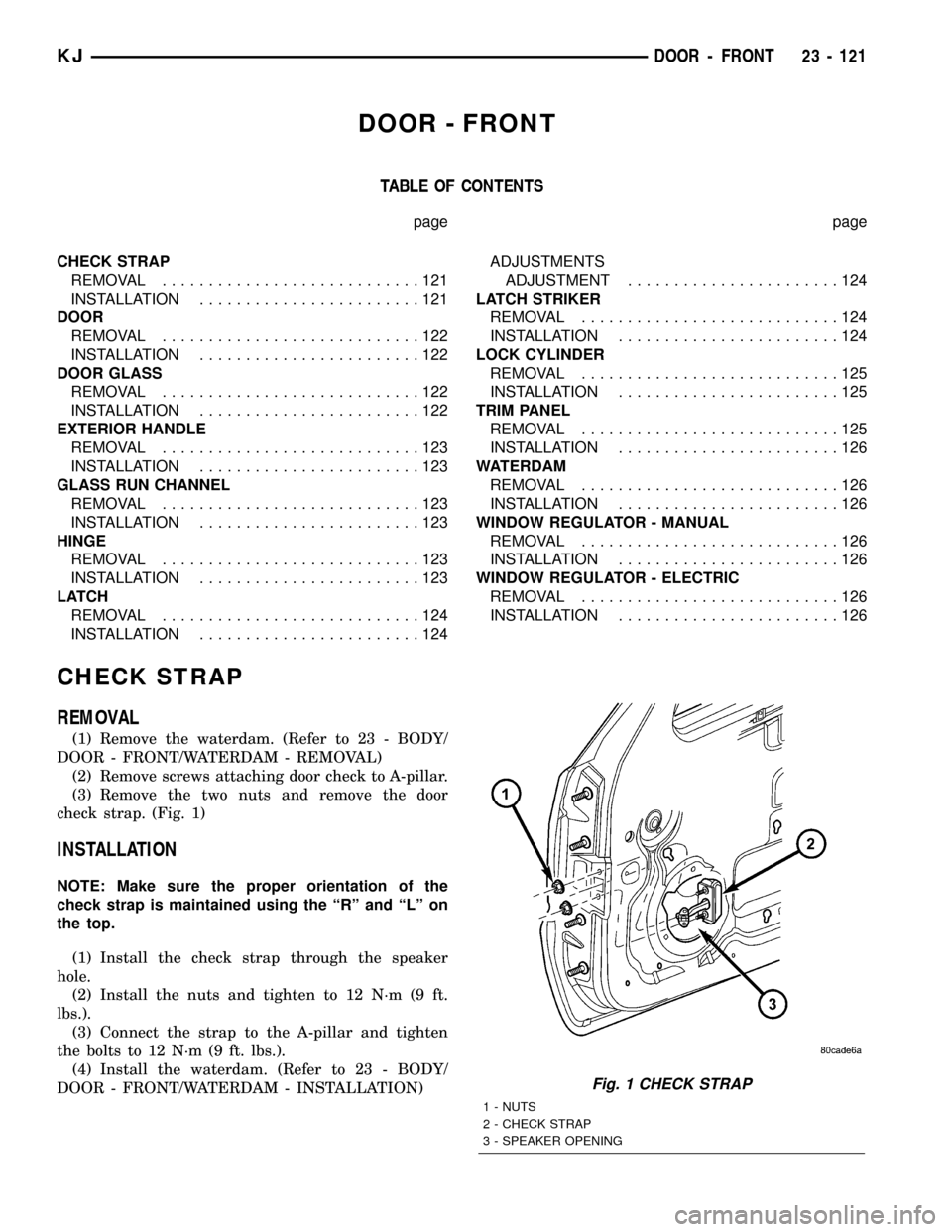
CHECK STRAP
REMOVAL
(1) Remove the waterdam. (Refer to 23 - BODY/
DOOR - FRONT/WATERDAM - REMOVAL)
(2) Remove screws attaching door check to A-pillar.
(3) Remove the two nuts and remove the door
check strap. (Fig. 1)
INSTALLATION
NOTE: Make sure the proper orientation of the
check strap is maintained using the ªRº and ªLº on
the top.
(1) Install the check strap through the speaker
hole.
(2) Install the nuts and tighten to 12 N´m (9 ft.
lbs.).
(3) Connect the strap to the A-pillar and tighten
the bolts to 12 N´m (9 ft. lbs.).
(4) Install the waterdam. (Refer to 23 - BODY/
DOOR - FRONT/WATERDAM - INSTALLATION)
Fig. 1 CHECK STRAP
1 - NUTS
2 - CHECK STRAP
3 - SPEAKER OPENING
KJDOOR - FRONT 23 - 121
Page 1587 of 1803
DOOR
REMOVAL
(1) Disconnect the door wire harness electrical con-
nector at the A-pillar.
(2) Support the door with a suitable lifting device.
(3) Remove the bolts attaching the check strap to
the a-pillar.
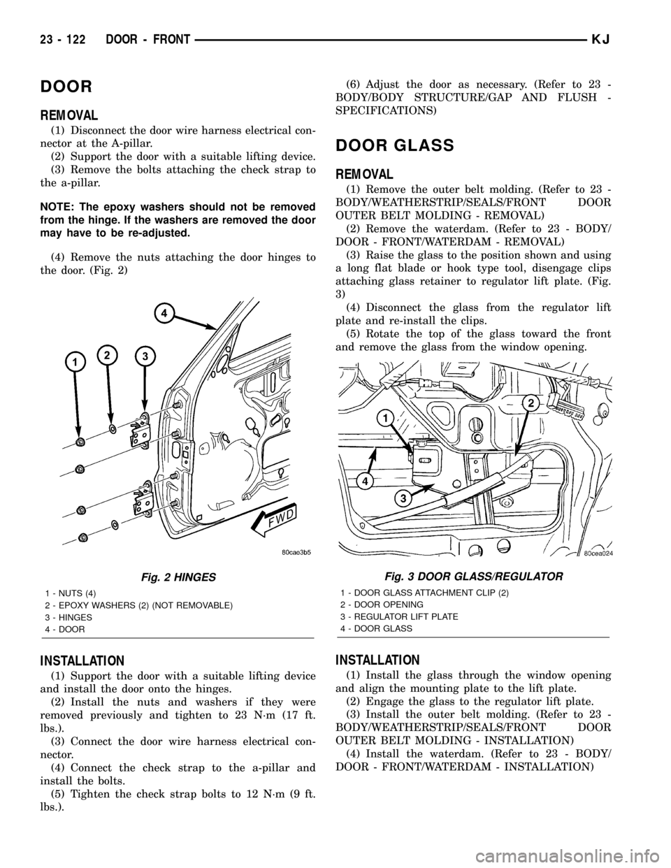
NOTE: The epoxy washers should not be removed
from the hinge. If the washers are removed the door
may have to be re-adjusted.
(4) Remove the nuts attaching the door hinges to
the door. (Fig. 2)
INSTALLATION
(1) Support the door with a suitable lifting device
and install the door onto the hinges.
(2) Install the nuts and washers if they were
removed previously and tighten to 23 N´m (17 ft.
lbs.).
(3) Connect the door wire harness electrical con-
nector.
(4) Connect the check strap to the a-pillar and
install the bolts.
(5) Tighten the check strap bolts to 12 N´m (9 ft.
lbs.).(6) Adjust the door as necessary. (Refer to 23 -
BODY/BODY STRUCTURE/GAP AND FLUSH -
SPECIFICATIONS)
DOOR GLASS
REMOVAL
(1) Remove the outer belt molding. (Refer to 23 -
BODY/WEATHERSTRIP/SEALS/FRONT DOOR
OUTER BELT MOLDING - REMOVAL)
(2) Remove the waterdam. (Refer to 23 - BODY/
DOOR - FRONT/WATERDAM - REMOVAL)
(3) Raise the glass to the position shown and using
a long flat blade or hook type tool, disengage clips
attaching glass retainer to regulator lift plate. (Fig.
3)
(4) Disconnect the glass from the regulator lift
plate and re-install the clips.
(5) Rotate the top of the glass toward the front
and remove the glass from the window opening.
INSTALLATION
(1) Install the glass through the window opening
and align the mounting plate to the lift plate.
(2) Engage the glass to the regulator lift plate.
(3) Install the outer belt molding. (Refer to 23 -
BODY/WEATHERSTRIP/SEALS/FRONT DOOR
OUTER BELT MOLDING - INSTALLATION)
(4) Install the waterdam. (Refer to 23 - BODY/
DOOR - FRONT/WATERDAM - INSTALLATION)
Fig. 2 HINGES
1 - NUTS (4)
2 - EPOXY WASHERS (2) (NOT REMOVABLE)
3 - HINGES
4 - DOOR
Fig. 3 DOOR GLASS/REGULATOR
1 - DOOR GLASS ATTACHMENT CLIP (2)
2 - DOOR OPENING
3 - REGULATOR LIFT PLATE
4 - DOOR GLASS
23 - 122 DOOR - FRONTKJ
Page 1591 of 1803
INSTALLATION
(1) Connect the inside handle actuator rod and the
electrical connectors.
(2) Position the trim panel and seat the clips fully.
(3) Instal the screws and install the screw plug.
WATERDAM
REMOVAL
(1) Remove the trim panel. (Refer to 23 - BODY/
DOOR - FRONT/TRIM PANEL - REMOVAL)
(2) Remove the door speaker.
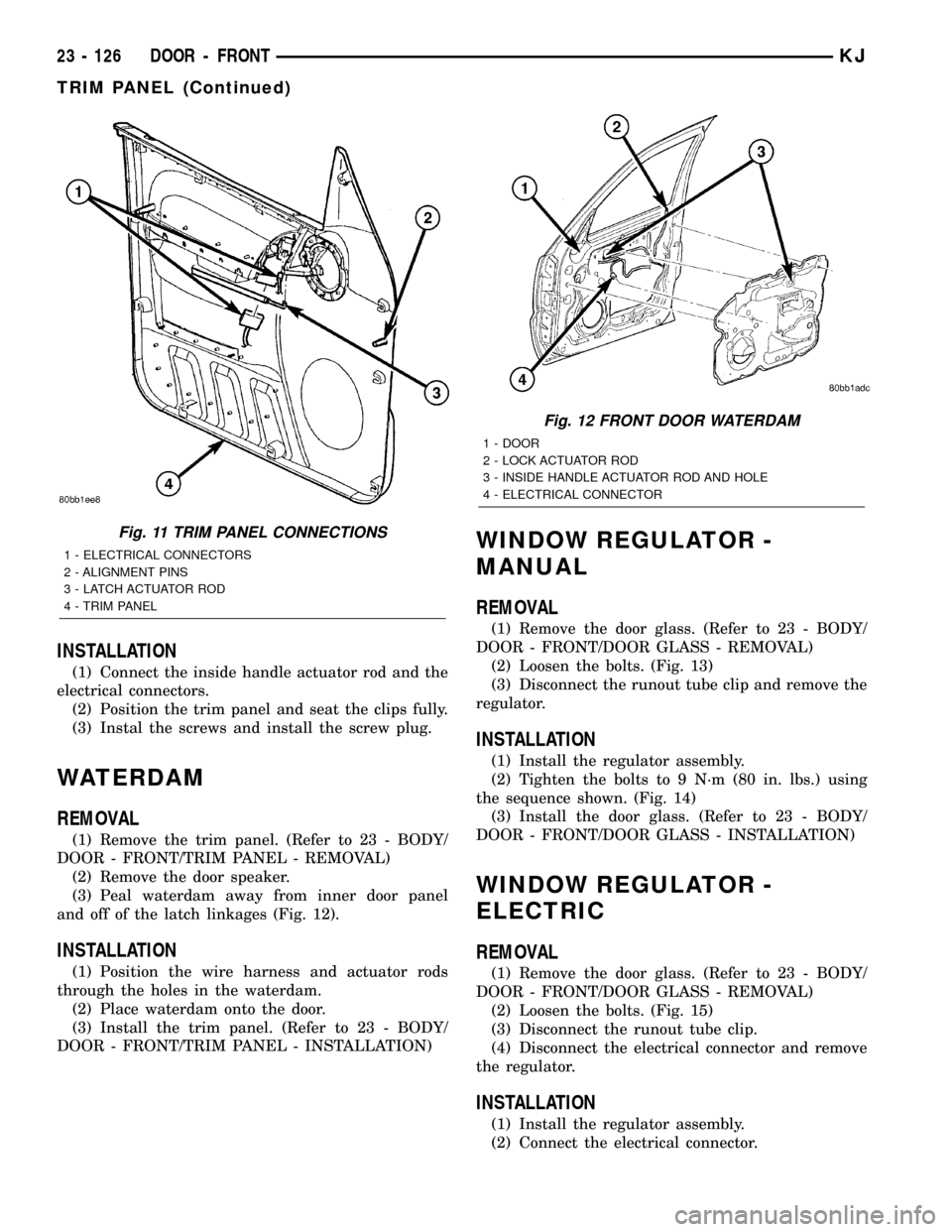
(3) Peal waterdam away from inner door panel
and off of the latch linkages (Fig. 12).
INSTALLATION
(1) Position the wire harness and actuator rods
through the holes in the waterdam.
(2) Place waterdam onto the door.
(3) Install the trim panel. (Refer to 23 - BODY/
DOOR - FRONT/TRIM PANEL - INSTALLATION)
WINDOW REGULATOR -
MANUAL
REMOVAL
(1) Remove the door glass. (Refer to 23 - BODY/
DOOR - FRONT/DOOR GLASS - REMOVAL)
(2) Loosen the bolts. (Fig. 13)
(3) Disconnect the runout tube clip and remove the
regulator.
INSTALLATION
(1) Install the regulator assembly.
(2) Tighten the bolts to 9 N´m (80 in. lbs.) using
the sequence shown. (Fig. 14)
(3) Install the door glass. (Refer to 23 - BODY/
DOOR - FRONT/DOOR GLASS - INSTALLATION)
WINDOW REGULATOR -
ELECTRIC
REMOVAL
(1) Remove the door glass. (Refer to 23 - BODY/
DOOR - FRONT/DOOR GLASS - REMOVAL)
(2) Loosen the bolts. (Fig. 15)
(3) Disconnect the runout tube clip.
(4) Disconnect the electrical connector and remove
the regulator.
INSTALLATION
(1) Install the regulator assembly.
(2) Connect the electrical connector.
Fig. 11 TRIM PANEL CONNECTIONS
1 - ELECTRICAL CONNECTORS
2 - ALIGNMENT PINS
3 - LATCH ACTUATOR ROD
4 - TRIM PANEL
Fig. 12 FRONT DOOR WATERDAM
1 - DOOR
2 - LOCK ACTUATOR ROD
3 - INSIDE HANDLE ACTUATOR ROD AND HOLE
4 - ELECTRICAL CONNECTOR
23 - 126 DOOR - FRONTKJ
TRIM PANEL (Continued)