2002 JEEP LIBERTY Plugs
[x] Cancel search: PlugsPage 438 of 1803

The turn signal indicators are connected in parallel
with the other turn signal circuits. This arrangement
allows the turn signal indicators to remain func-
tional, regardless of the condition of the other cir-
cuits in the turn signal and hazard warning systems.
The combination flasher outputs of the hazard switch
to the instrument cluster turn signal indicator inputs
can be diagnosed using conventional diagnostic tools
and methods. (Refer to 8 - ELECTRICAL/LAMPS/
LIGHTING - EXTERIOR/HAZARD SWITCH -
DESCRIPTION) for more information on the combi-
nation flasher and hazard switch operation.
WAIT-TO-START INDICATOR
DESCRIPTION
A wait-to-start indicator is only found in the
instrument clusters of vehicles equipped with an
optional diesel engine. The wait-to-start indicator is
located above the fuel gauge and to the left of the
tachometer in the instrument cluster. The wait-to-
start indicator consists of a stencil-like cutout of the
International Control and Display Symbol icon for
ªDiesel Preheatº in the opaque layer of the instru-
ment cluster overlay. The dark outer layer of the
overlay prevents the indicator from being clearly vis-
ible when it is not illuminated. An amber Light
Emitting Diode (LED) behind the cutout in the
opaque layer of the overlay causes the icon to appear
in amber through the translucent outer layer of the
overlay when it is illuminated from behind by the
LED, which is soldered onto the instrument cluster
electronic circuit board. The wait-to-start indicator is
serviced as a unit with the instrument cluster.
OPERATION
The wait-to-start indicator gives an indication to
the vehicle operator when the diesel engine glow
plugs are energized in their pre-heat operating mode.
This indicator is controlled by a transistor on the
instrument cluster electronic circuit board based
upon the cluster programming and electronic mes-
sages received by the cluster from the Powertrain
Control Module (PCM) over the Programmable Com-
munications Interface (PCI) data bus. The wait-to-
start indicator Light Emitting Diode (LED) is
completely controlled by the instrument cluster logic
circuit, and that logic will only allow this indicator to
operate when the instrument cluster receives a bat-
tery current input on the fused ignition switch out-
put (run-start) circuit. Therefore, the LED will
always be off when the ignition switch is in any posi-
tion except On or Start. The LED only illuminates
when it is provided a path to ground by the instru-
ment cluster transistor. The instrument cluster willturn on the wait-to-start indicator for the following
reasons:
²Wait-To-Start Lamp-On Message- Each time
the cluster receives a wait-to-start lamp-on message
from the PCM indicating the glow plugs are heating
and the driver must wait to start the engine, the
wait-to-start indicator will be illuminated. The indi-
cator remains illuminated until the cluster receives a
wait-to-start lamp-off message, or until the ignition
switch is turned to the Off position, whichever occurs
first.
²Actuator Test- Each time the cluster is put
through the actuator test, the wait-to-start indicator
will be turned on, then off again during the bulb
check portion of the test to confirm the functionality
of the LED and the cluster control circuitry.
The PCM continually monitors the ambient tem-
perature and the glow plug pre-heater circuits to
determine how long the glow plugs must be heated in
the pre-heat operating mode. The PCM then sends
the proper wait-to-start lamp-on and lamp-off mes-
sages to the instrument cluster. For further diagnosis
of the wait-to-start indicator or the instrument clus-
ter circuitry that controls the indicator, (Refer to 8 -
ELECTRICAL/INSTRUMENT CLUSTER - DIAGNO-
SIS AND TESTING). For proper diagnosis of the
glow plug pre-heater control circuits, the PCM, the
PCI data bus, or the electronic message inputs to the
instrument cluster that control the wait-to-start indi-
cator, a DRBIIItscan tool is required. Refer to the
appropriate diagnostic information.
WASHER FLUID INDICATOR
DESCRIPTION
A washer fluid indicator is standard equipment on
all instrument clusters. The washer fluid indicator
consists of the text ªlowashº, which appears in place
of the odometer/trip odometer information in the Vac-
uum-Fluorescent Display (VFD) of the instrument
cluster. The VFD is part of the cluster electronic cir-
cuit board, and is visible through a cutout located
near the lower edge of the speedometer dial face in
the instrument cluster. The dark outer layer of the
overlay prevents the VFD from being clearly visible
when it is not illuminated. The text message
ªlowashº appears in the same blue-green color and at
the same lighting level as the odometer/trip odometer
information through the translucent outer layer of
the overlay when it is illuminated by the instrument
cluster electronic circuit board. The washer fluid
indicator is serviced as a unit with the instrument
cluster.
KJINSTRUMENT CLUSTER 8J - 35
TURN SIGNAL INDICATOR (Continued)
Page 762 of 1803

8W-02 COMPONENT INDEX
Component Page
A/C Compressor Clutch Relay........... 8Wa-42
A/C Compressor Clutch................ 8Wa-42
A/C-Heater Control................... 8Wa-42
A/C High Pressure Switch.............. 8Wa-42
A/C Low Pressure Switch............... 8Wa-42
A/C Pressure Transducer............... 8Wa-42
Accelerator Pedal Position Sensor........ 8Wa-30
Airbag Control Module................. 8Wa-43
Ambient Temperature Sensor............ 8Wa-45
Antenna Module...................... 8Wa-47
Antenna............................ 8Wa-47
Ash Receiver Lamp................... 8Wa-44
Auto Shut Down Relay................. 8Wa-30
Back-Up Lamp Switch................. 8Wa-31
Battery Temperature Sensor......... 8Wa-20, 30
Battery............................. 8Wa-20
Blend Door Actuator................... 8Wa-42
Blower Motor Relay................... 8Wa-42
Blower Motor Resistor Block............ 8Wa-42
Blower Motor........................ 8Wa-42
Body Control Module.................. 8Wa-45
Boost Pressure Sensor................. 8Wa-30
Brake Lamp Switch................... 8Wa-33
Brake Pressure Switch................. 8Wa-35
Cabin Heater Relay................... 8Wa-42
Cabin Heater........................ 8Wa-42
Camshaft Position Sensor.............. 8Wa-30
Capacitor........................... 8Wa-30
Cargo Lamp......................... 8Wa-44
CD Changer......................... 8Wa-47
Center High Mounted Stop Lamp........ 8Wa-51
Cigar Lighter........................ 8Wa-41
Circuit Breakers...................... 8Wa-12
Clockspring................. 8Wa-33, 41, 43, 47
Clutch Interlock Switch................ 8Wa-21
Clutch Switch Override Relay........... 8Wa-21
Coil On Plugs........................ 8Wa-30
Coil Rail............................ 8Wa-30
Compass Mini-Trip Computer........... 8Wa-49
Controller Antilock Brake.............. 8Wa-35
Courtesy Lamps...................... 8Wa-44
Crankshaft Position Sensor............. 8Wa-30
Curtain Airbags...................... 8Wa-43
Cylinder Lock Switches................ 8Wa-61
Data Link Connector.................. 8Wa-18
Daytime Running Lamp Relay........... 8Wa-50
Defogger Relay....................... 8Wa-48
Diagnostic Junction Port............... 8Wa-18
Dome Lamp......................... 8Wa-44
Door Ajar Switches.................... 8Wa-45
Door Lock Motor/Ajar Switches.......... 8Wa-61
Door Lock Relay...................... 8Wa-61Component Page
Door Lock Switches................... 8Wa-61
Door Speakers....................... 8Wa-47
Driver Airbag Squib 1................. 8Wa-43
Driver Airbag Squib 2................. 8Wa-43
Driver Door Unlock Relay.............. 8Wa-61
Driver Seat Belt Switch................ 8Wa-40
Driver Seat Belt Tensioner.............. 8Wa-43
EGR Solenoid........................ 8Wa-30
Electric Brake Provision................ 8Wa-54
Engine Control Module................ 8Wa-30
Engine Coolant Level Sensor............ 8Wa-40
Engine Coolant Temperature Sensor...... 8Wa-30
Engine Oil Pressure Sensor............. 8Wa-30
EVAP/Purge Solenoid.................. 8Wa-30
Flip-Up Glass Release Motor............ 8Wa-61
Flip-Up Glass Release Switch........... 8Wa-61
Fog Lamps.......................... 8Wa-50
Front Fog Lamp Relay................. 8Wa-50
Front Wiper Motor.................... 8Wa-53
Fuel Heater Relay.................... 8Wa-30
Fuel Heater......................... 8Wa-30
Fuel Injectors........................ 8Wa-30
Fuel Pressure Sensor.................. 8Wa-30
Fuel Pressure Solenoid................. 8Wa-30
Fuel Pump Module.................... 8Wa-30
Fuel Pump Relay..................... 8Wa-30
Fuses........................... 8Wa-10, 12
Fusible Link......................... 8Wa-20
Grounds............................ 8Wa-15
Generator........................... 8Wa-20
Glow Plugs.......................... 8Wa-30
Hazard Switch/Combination Flasher...... 8Wa-52
Headlamp Leveling Switch.............. 8Wa-50
Headlamps.......................... 8Wa-50
Heated Seats........................ 8Wa-63
High Beam Relay..................... 8Wa-50
Horns.............................. 8Wa-41
Hood Ajar Switch..................... 8Wa-45
Idle Air Control Motor................. 8Wa-30
Ignition Switch....................... 8Wa-10
Impact Sensors....................... 8Wa-43
Input Speed Sensor................... 8Wa-31
Instrument Cluster................... 8Wa-40
Instrument Panel Speakers............. 8Wa-47
Intake Air Temperature Sensor.......... 8Wa-30
Intrusion Sensor..................... 8Wa-49
Junction Block....................... 8Wa-12
Knock Sensor........................ 8Wa-30
Leak Detection Pump.................. 8Wa-30
Leveling Motors...................... 8Wa-50
License Lamp........................ 8Wa-51
Line Pressure Sensor.................. 8Wa-31
KJ8W-02 COMPONENT INDEX8Wa-02-1
Page 1216 of 1803
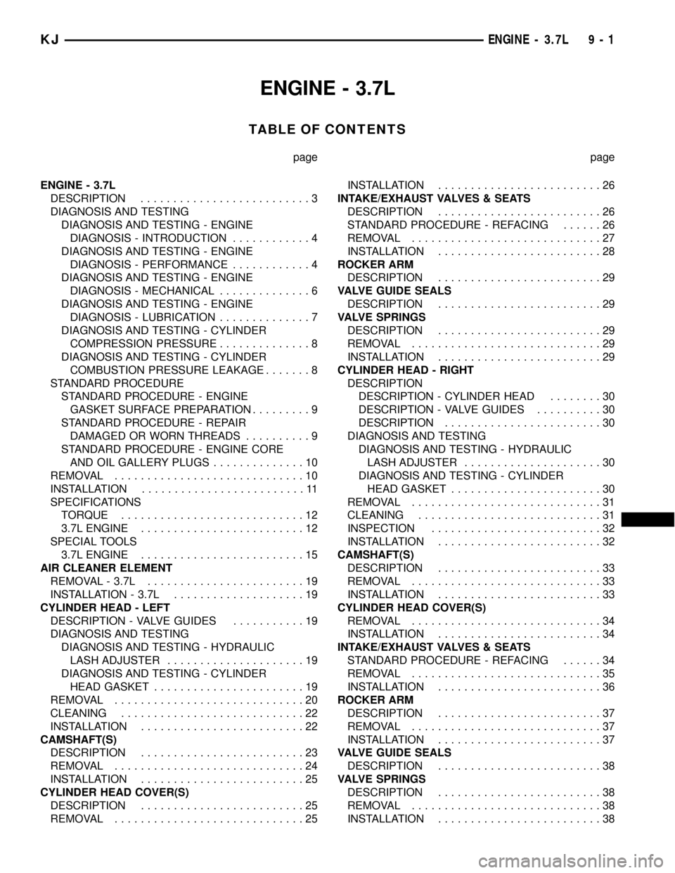
ENGINE - 3.7L
TABLE OF CONTENTS
page page
ENGINE - 3.7L
DESCRIPTION..........................3
DIAGNOSIS AND TESTING
DIAGNOSIS AND TESTING - ENGINE
DIAGNOSIS - INTRODUCTION............4
DIAGNOSIS AND TESTING - ENGINE
DIAGNOSIS - PERFORMANCE............4
DIAGNOSIS AND TESTING - ENGINE
DIAGNOSIS - MECHANICAL..............6
DIAGNOSIS AND TESTING - ENGINE
DIAGNOSIS - LUBRICATION..............7
DIAGNOSIS AND TESTING - CYLINDER
COMPRESSION PRESSURE..............8
DIAGNOSIS AND TESTING - CYLINDER
COMBUSTION PRESSURE LEAKAGE.......8
STANDARD PROCEDURE
STANDARD PROCEDURE - ENGINE
GASKET SURFACE PREPARATION.........9
STANDARD PROCEDURE - REPAIR
DAMAGED OR WORN THREADS..........9
STANDARD PROCEDURE - ENGINE CORE
AND OIL GALLERY PLUGS..............10
REMOVAL.............................10
INSTALLATION.........................11
SPECIFICATIONS
TORQUE............................12
3.7L ENGINE.........................12
SPECIAL TOOLS
3.7L ENGINE.........................15
AIR CLEANER ELEMENT
REMOVAL - 3.7L........................19
INSTALLATION - 3.7L....................19
CYLINDER HEAD - LEFT
DESCRIPTION - VALVE GUIDES...........19
DIAGNOSIS AND TESTING
DIAGNOSIS AND TESTING - HYDRAULIC
LASH ADJUSTER.....................19
DIAGNOSIS AND TESTING - CYLINDER
HEAD GASKET.......................19
REMOVAL.............................20
CLEANING............................22
INSTALLATION.........................22
CAMSHAFT(S)
DESCRIPTION.........................23
REMOVAL.............................24
INSTALLATION.........................25
CYLINDER HEAD COVER(S)
DESCRIPTION.........................25
REMOVAL.............................25INSTALLATION.........................26
INTAKE/EXHAUST VALVES & SEATS
DESCRIPTION.........................26
STANDARD PROCEDURE - REFACING......26
REMOVAL.............................27
INSTALLATION.........................28
ROCKER ARM
DESCRIPTION.........................29
VALVE GUIDE SEALS
DESCRIPTION.........................29
VALVE SPRINGS
DESCRIPTION.........................29
REMOVAL.............................29
INSTALLATION.........................29
CYLINDER HEAD - RIGHT
DESCRIPTION
DESCRIPTION - CYLINDER HEAD........30
DESCRIPTION - VALVE GUIDES..........30
DESCRIPTION........................30
DIAGNOSIS AND TESTING
DIAGNOSIS AND TESTING - HYDRAULIC
LASH ADJUSTER.....................30
DIAGNOSIS AND TESTING - CYLINDER
HEAD GASKET.......................30
REMOVAL.............................31
CLEANING............................31
INSPECTION..........................32
INSTALLATION.........................32
CAMSHAFT(S)
DESCRIPTION.........................33
REMOVAL.............................33
INSTALLATION.........................33
CYLINDER HEAD COVER(S)
REMOVAL.............................34
INSTALLATION.........................34
INTAKE/EXHAUST VALVES & SEATS
STANDARD PROCEDURE - REFACING......34
REMOVAL.............................35
INSTALLATION.........................36
ROCKER ARM
DESCRIPTION.........................37
REMOVAL.............................37
INSTALLATION.........................37
VALVE GUIDE SEALS
DESCRIPTION.........................38
VALVE SPRINGS
DESCRIPTION.........................38
REMOVAL.............................38
INSTALLATION.........................38
KJENGINE - 3.7L 9 - 1
Page 1220 of 1803
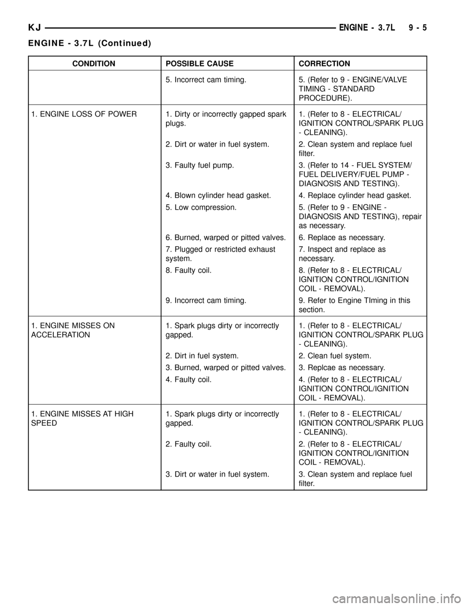
CONDITION POSSIBLE CAUSE CORRECTION
5. Incorrect cam timing. 5. (Refer to 9 - ENGINE/VALVE
TIMING - STANDARD
PROCEDURE).
1. ENGINE LOSS OF POWER 1. Dirty or incorrectly gapped spark
plugs.1. (Refer to 8 - ELECTRICAL/
IGNITION CONTROL/SPARK PLUG
- CLEANING).
2. Dirt or water in fuel system. 2. Clean system and replace fuel
filter.
3. Faulty fuel pump. 3. (Refer to 14 - FUEL SYSTEM/
FUEL DELIVERY/FUEL PUMP -
DIAGNOSIS AND TESTING).
4. Blown cylinder head gasket. 4. Replace cylinder head gasket.
5. Low compression. 5. (Refer to 9 - ENGINE -
DIAGNOSIS AND TESTING), repair
as necessary.
6. Burned, warped or pitted valves. 6. Replace as necessary.
7. Plugged or restricted exhaust
system.7. Inspect and replace as
necessary.
8. Faulty coil. 8. (Refer to 8 - ELECTRICAL/
IGNITION CONTROL/IGNITION
COIL - REMOVAL).
9. Incorrect cam timing. 9. Refer to Engine TIming in this
section.
1. ENGINE MISSES ON
ACCELERATION1. Spark plugs dirty or incorrectly
gapped.1. (Refer to 8 - ELECTRICAL/
IGNITION CONTROL/SPARK PLUG
- CLEANING).
2. Dirt in fuel system. 2. Clean fuel system.
3. Burned, warped or pitted valves. 3. Replcae as necessary.
4. Faulty coil. 4. (Refer to 8 - ELECTRICAL/
IGNITION CONTROL/IGNITION
COIL - REMOVAL).
1. ENGINE MISSES AT HIGH
SPEED1. Spark plugs dirty or incorrectly
gapped.1. (Refer to 8 - ELECTRICAL/
IGNITION CONTROL/SPARK PLUG
- CLEANING).
2. Faulty coil. 2. (Refer to 8 - ELECTRICAL/
IGNITION CONTROL/IGNITION
COIL - REMOVAL).
3. Dirt or water in fuel system. 3. Clean system and replace fuel
filter.
KJENGINE - 3.7L 9 - 5
ENGINE - 3.7L (Continued)
Page 1223 of 1803
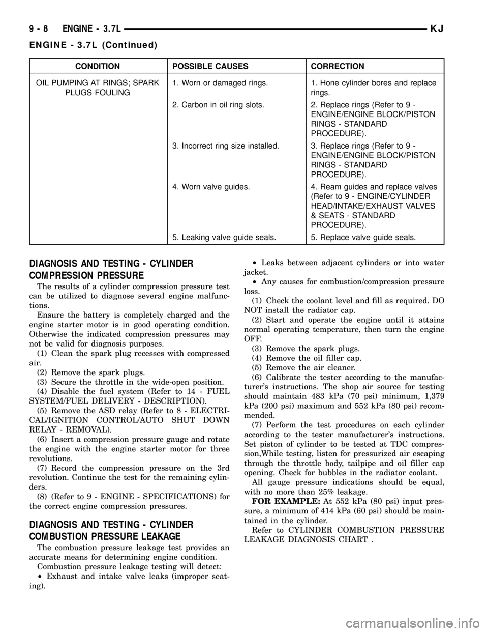
CONDITION POSSIBLE CAUSES CORRECTION
OIL PUMPING AT RINGS; SPARK
PLUGS FOULING1. Worn or damaged rings. 1. Hone cylinder bores and replace
rings.
2. Carbon in oil ring slots. 2. Replace rings (Refer to 9 -
ENGINE/ENGINE BLOCK/PISTON
RINGS - STANDARD
PROCEDURE).
3. Incorrect ring size installed. 3. Replace rings (Refer to 9 -
ENGINE/ENGINE BLOCK/PISTON
RINGS - STANDARD
PROCEDURE).
4. Worn valve guides. 4. Ream guides and replace valves
(Refer to 9 - ENGINE/CYLINDER
HEAD/INTAKE/EXHAUST VALVES
& SEATS - STANDARD
PROCEDURE).
5. Leaking valve guide seals. 5. Replace valve guide seals.
DIAGNOSIS AND TESTING - CYLINDER
COMPRESSION PRESSURE
The results of a cylinder compression pressure test
can be utilized to diagnose several engine malfunc-
tions.
Ensure the battery is completely charged and the
engine starter motor is in good operating condition.
Otherwise the indicated compression pressures may
not be valid for diagnosis purposes.
(1) Clean the spark plug recesses with compressed
air.
(2) Remove the spark plugs.
(3) Secure the throttle in the wide-open position.
(4) Disable the fuel system (Refer to 14 - FUEL
SYSTEM/FUEL DELIVERY - DESCRIPTION).
(5) Remove the ASD relay (Refer to 8 - ELECTRI-
CAL/IGNITION CONTROL/AUTO SHUT DOWN
RELAY - REMOVAL).
(6) Insert a compression pressure gauge and rotate
the engine with the engine starter motor for three
revolutions.
(7) Record the compression pressure on the 3rd
revolution. Continue the test for the remaining cylin-
ders.
(8) (Refer to 9 - ENGINE - SPECIFICATIONS) for
the correct engine compression pressures.
DIAGNOSIS AND TESTING - CYLINDER
COMBUSTION PRESSURE LEAKAGE
The combustion pressure leakage test provides an
accurate means for determining engine condition.
Combustion pressure leakage testing will detect:
²Exhaust and intake valve leaks (improper seat-
ing).²Leaks between adjacent cylinders or into water
jacket.
²Any causes for combustion/compression pressure
loss.
(1) Check the coolant level and fill as required. DO
NOT install the radiator cap.
(2) Start and operate the engine until it attains
normal operating temperature, then turn the engine
OFF.
(3) Remove the spark plugs.
(4) Remove the oil filler cap.
(5) Remove the air cleaner.
(6) Calibrate the tester according to the manufac-
turer's instructions. The shop air source for testing
should maintain 483 kPa (70 psi) minimum, 1,379
kPa (200 psi) maximum and 552 kPa (80 psi) recom-
mended.
(7) Perform the test procedures on each cylinder
according to the tester manufacturer's instructions.
Set piston of cylinder to be tested at TDC compres-
sion,While testing, listen for pressurized air escaping
through the throttle body, tailpipe and oil filler cap
opening. Check for bubbles in the radiator coolant.
All gauge pressure indications should be equal,
with no more than 25% leakage.
FOR EXAMPLE:At 552 kPa (80 psi) input pres-
sure, a minimum of 414 kPa (60 psi) should be main-
tained in the cylinder.
Refer to CYLINDER COMBUSTION PRESSURE
LEAKAGE DIAGNOSIS CHART .
9 - 8 ENGINE - 3.7LKJ
ENGINE - 3.7L (Continued)
Page 1225 of 1803
²Tapping the hole with a special Heli-Coil Tap, or
equivalent.
²Installing an insert into the tapped hole to bring
the hole back to its original thread size.
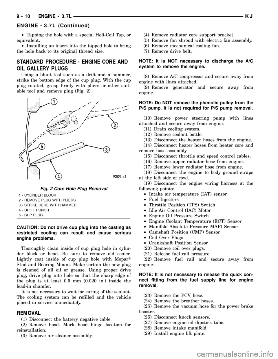
STANDARD PROCEDURE - ENGINE CORE AND
OIL GALLERY PLUGS
Using a blunt tool such as a drift and a hammer,
strike the bottom edge of the cup plug. With the cup
plug rotated, grasp firmly with pliers or other suit-
able tool and remove plug (Fig. 2).
CAUTION: Do not drive cup plug into the casting as
restricted cooling can result and cause serious
engine problems.
Thoroughly clean inside of cup plug hole in cylin-
der block or head. Be sure to remove old sealer.
Lightly coat inside of cup plug hole with Mopart
Stud and Bearing Mount. Make certain the new plug
is cleaned of all oil or grease. Using proper drive
plug, drive plug into hole so that the sharp edge of
the plug is at least 0.5 mm (0.020 in.) inside the
lead-in chamfer.
It is not necessary to wait for curing of the sealant.
The cooling system can be refilled and the vehicle
placed in service immediately.
REMOVAL
(1) Disconnect the battery negative cable.
(2) Remove hood. Mark hood hinge location for
reinstallation.
(3) Remove air cleaner assembly.(4) Remove radiator core support bracket.
(5) Remove fan shroud with electric fan assembly.
(6) Remove mechanical cooling fan.
(7) Remove drive belt.
NOTE: It is NOT necessary to discharge the A/C
system to remove the engine.
(8) Remove A/C compressor and secure away from
engine with lines attached.
(9) Remove generator and secure away from
engine.
NOTE: Do NOT remove the phenolic pulley from the
P/S pump. It is not required for P/S pump removal.
(10) Remove power steering pump with lines
attached and secure away from engine.
(11) Drain cooling system.
(12) Remove coolant bottle.
(13) Disconnect the heater hoses from the engine.
(14) Disconnect heater hoses from heater core and
remove hose assembly.
(15) Disconnect throttle and speed control cables.
(16) Remove upper radiator hose from engine.
(17) Remove lower radiator hose from engine.
(18) Disconnect the engine to body ground straps
at the left side of cowl.
(19) Disconnect the engine wiring harness at the
following points:
²Intake air temperature (IAT) sensor
²Fuel Injectors
²Throttle Position (TPS) Switch
²Idle Air Control (IAC) Motor
²Engine Oil Pressure Switch
²Engine Coolant Temperature (ECT) Sensor
²Manifold Absolute Pressure MAP) Sensor
²Camshaft Position (CMP) Sensor
²Coil Over Plugs
²Crankshaft Position Sensor
(20) Remove coil over plugs.
(21) Release fuel rail pressure.
(22) Remove fuel rail and secure away from
engine.
NOTE: It is not necessary to release the quick con-
nect fitting from the fuel supply line for engine
removal.
(23) Remove the PCV hose.
(24) Remove the breather hoses.
(25) Remove the vacuum hose for the power brake
booster.
(26) Disconnect knock sensors.
(27) Remove engine oil dipstick tube.
(28) Remove intake manifold.
(29) Install engine lift plate.
Fig. 2 Core Hole Plug Removal
1 - CYLINDER BLOCK
2 - REMOVE PLUG WITH PLIERS
3 - STRIKE HERE WITH HAMMER
4 - DRIFT PUNCH
5 - CUP PLUG
9 - 10 ENGINE - 3.7LKJ
ENGINE - 3.7L (Continued)
Page 1226 of 1803

NOTE: Recheck bolt torque for engine lift plate
before removing engine.
(30) Secure the left and right engine wiring har-
nesses away from engine.
(31) Raise vehicle.
(32) Disconnect oxygen sensor wiring.
(33) Disconnect crankshaft postion sensor.
(34) Disconnect the engine block heater power
cable, if equipped.
(35) Disconnect the front propshaft at the front
differential and secure out of way.
NOTE: It is necessary to disconnect the front prop-
shaft for access to the starter and left side exhaust
flange.
(36) Remove the starter.
(37) Remove the ground straps from the left and
right side of the block.
(38) Disconnect the right and left exhaust pipes at
the manifolds and from the crossover, and remove
from the vehicle.
NOTE: The exhaust clamps at the manifolds cannot
be reused. New clamps must be used or leaks may
occur.
NOTE: For manual transmission vehicles, the trans-
mission must be removed from the vehicle, before
the engine can be removed. The manual transmis-
sion will contact the floorpan before the engine
clears the motor mounts, so it must be removed.
(39) Remove the structural cover.
(40) Remove torque convertor bolts, and mark
location for reassembly.
(41) Remove transmission bellhousing to engine
bolts.
(42) Loosen left and right engine mount thru bolts.
NOTE: It is not necessary to completely remove
engine mount thru bolts, for engine removal.
(43) Lower the vehicle.
(44) Support the transmission with a suitable jack.
(45) Connect a suitable engine hoist to the engine
lift plate.
(46) Remove engine from vehicle.
INSTALLATION
(1) Position the engine in the vehicle.
(2) Install both left and right side engine mounts
onto engine.
(3) Raise the vehicle.(4) Install the transmission bellhousing to engine
mounting bolts. Tighten the bolts to 41 N´m (30ft.
lbs.).
(5) Tighten the engine mount thru bolts.
(6) Install the torque convertor bolts.
(7) Connect the ground straps on the left and right
side of the engine.
(8) Install the starter.
(9) Connect the crankshaft position sensor.
(10) Install the engine block heater power cable, if
equipped.
CAUTION: The structural cover requires a specific
torque sequence. Failure to follow this sequence
may cause severe damage to the cover.
(11) Install the structural cover.
NOTE: New clamps must be used on exhaust man-
ifold flanges. Failure to use new clamps may result
in exhaust leaks.
(12) Install the left and right exhaust pipes.
(13) Connect the left and right oxygen sensors.
(14) Lower vehicle.
(15) Remove the engine lift plate.
(16) Connect the knock sensors.
(17) Connect the engine to body ground straps at
the left side of the cowl.
(18) Install the intake manifold.
(19) Install the engine oil dipstick tube.
(20) Install the power brake booster vacuum hose.
(21) Install the breather hoses.
(22) Install the PCV hose.
(23) Install the fuel rail.
(24) Install the coil over plugs.
(25) Connect the engine wiring harness at the fol-
lowing points:
²Intake air temperature (IAT) sensor
²Fuel Injectors
²Throttle Position (TPS) Switch
²Idle Air Control (IAC) Motor
²Engine Oil Pressure Switch
²Engine Coolant Temperature (ECT) Sensor
²Manifold Absolute Pressure MAP) Sensor
²Camshaft Position (CMP) Sensor
²Coil Over Plugs
²Crankshaft Position Sensor
(26) Connect lower radiator hose.
(27) Connect upper radiator hose.
(28) Connect throttle and speed control cables.
(29) Install the heater hose assembly.
(30) Install coolant recovery bottle.
(31) Install the power steering pump.
(32) Install the generator.
(33) Install the A/C compressor.
(34) Install the drive belt.
KJENGINE - 3.7L 9 - 11
ENGINE - 3.7L (Continued)
Page 1237 of 1803
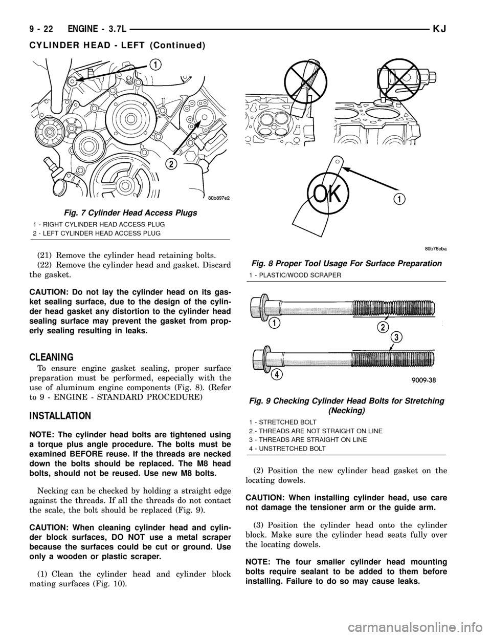
(21) Remove the cylinder head retaining bolts.
(22) Remove the cylinder head and gasket. Discard
the gasket.
CAUTION: Do not lay the cylinder head on its gas-
ket sealing surface, due to the design of the cylin-
der head gasket any distortion to the cylinder head
sealing surface may prevent the gasket from prop-
erly sealing resulting in leaks.
CLEANING
To ensure engine gasket sealing, proper surface
preparation must be performed, especially with the
use of aluminum engine components (Fig. 8). (Refer
to 9 - ENGINE - STANDARD PROCEDURE)
INSTALLATION
NOTE: The cylinder head bolts are tightened using
a torque plus angle procedure. The bolts must be
examined BEFORE reuse. If the threads are necked
down the bolts should be replaced. The M8 head
bolts, should not be reused. Use new M8 bolts.
Necking can be checked by holding a straight edge
against the threads. If all the threads do not contact
the scale, the bolt should be replaced (Fig. 9).
CAUTION: When cleaning cylinder head and cylin-
der block surfaces, DO NOT use a metal scraper
because the surfaces could be cut or ground. Use
only a wooden or plastic scraper.
(1) Clean the cylinder head and cylinder block
mating surfaces (Fig. 10).(2) Position the new cylinder head gasket on the
locating dowels.
CAUTION: When installing cylinder head, use care
not damage the tensioner arm or the guide arm.
(3) Position the cylinder head onto the cylinder
block. Make sure the cylinder head seats fully over
the locating dowels.
NOTE: The four smaller cylinder head mounting
bolts require sealant to be added to them before
installing. Failure to do so may cause leaks.
Fig. 7 Cylinder Head Access Plugs
1 - RIGHT CYLINDER HEAD ACCESS PLUG
2 - LEFT CYLINDER HEAD ACCESS PLUG
Fig. 8 Proper Tool Usage For Surface Preparation
1 - PLASTIC/WOOD SCRAPER
Fig. 9 Checking Cylinder Head Bolts for Stretching
(Necking)
1 - STRETCHED BOLT
2 - THREADS ARE NOT STRAIGHT ON LINE
3 - THREADS ARE STRAIGHT ON LINE
4 - UNSTRETCHED BOLT
9 - 22 ENGINE - 3.7LKJ
CYLINDER HEAD - LEFT (Continued)