Page 1156 of 1803
8W-91 CONNECTOR/GROUND/SPLICE LOCATION
TABLE OF CONTENTS
page
CONNECTOR/GROUND/SPLICE LOCATION
DESCRIPTION..........................1
CONNECTOR/GROUND/SPLICE
LOCATION
DESCRIPTION
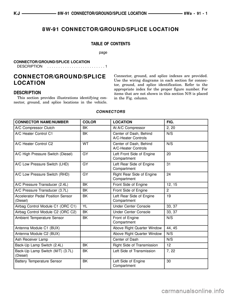
This section provides illustrations identifying con-
nector, ground, and splice locations in the vehicle.Connector, ground, and splice indexes are provided.
Use the wiring diagrams in each section for connec-
tor, ground, and splice identification. Refer to the
appropriate index for the proper figure number. For
items that are not shown in this section N/S is placed
in the Fig. column.
CONNECTORS
CONNECTOR NAME/NUMBER COLOR LOCATION FIG.
A/C Compressor Clutch BK At A/C Compressor 2, 20
A/C Heater Control C1 BK Center of Dash, Behind
A/C-Heater ControlsN/S
A/C Heater Control C2 WT Center of Dash, Behind
A/C-Heater ControlsN/S
A/C High Pressure Switch (Diesel) GY Left Front Side of Engine
Compartment20
A/C Low Pressure Switch (LHD) GY Left Rear Side of Engine
Compartment31
A/C Low Pressure Switch (RHD) GY Right Rear Side of Engine
Compartment24
A/C Pressure Transducer (2.4L) BK Front Side of Engine 12, 15
A/C Pressure Transducer (3.7L) BK Front Side of Engine 2
Accelerator Pedal Position Sensor
(Diesel)BK Left Rear Side of Engine
Compartment19
Airbag Control Module C1 (ORC C1) YL Under Center Console 33, 37
Airbag Control Module C2 (ORC C2) BK Under Center Console 33, 37
Ambient Temperature Sensor BK Front of Engine
CompartmentN/S
Antenna Module C1 (BUX) Above Right Quarter Window 44, 45
Antenna Module C2 (BUX) Above Right Quarter Window N/S
Ash Receiver Lamp Center of Dash N/S
Back-Up Lamp Switch (2.4L) BK Right Side of Transmission 12
Back-Up Lamp Switch (M/T) (3.7L)
(Diesel)BK Left Side of Transmission 7, 22
Battery Temperature Sensor BK Left Side of Engine
Compartment30
KJ8W-91 CONNECTOR/GROUND/SPLICE LOCATION8Wa-91-1
Page 1287 of 1803
(2) To determine if the secondary timing chains
are worn, rotate the engine clockwise until maximum
tensioner piston extension is obtained. Measure the
distance between the secondary timing chain ten-
sioner housing and the step ledge on the piston. The
measurement at point (A) must be less than 15mm
(.5906 inches).
(3) If the measurement exceeds the specification
the secondary timing chains are worn and require
replacement. Refer to Timing Chain and Sprockets in
this section for procedure.
SERVICE PROCEDURES
TIMING VERIFICATION
CAUTION: The 3.7L is a non free-wheeling design
engine. Therefore, correct engine timing is critical.
NOTE: Components referred to as left hand or right
hand are as viewed from the drivers position inside
the vehicle.
NOTE: The blue link plates on the chains and the
dots on the camshaft drive sprockets may not line
up during the timing verification procedure. The
blue link plates are lined up with the sprocket dots
only when re-timing the complete timing drive.
Once the timing drive is rotated blue link-to-dot
alignment is no longer valid.
Engine base timing can be verified by the following
procedure:
(1) Remove the cylinder head covers. Refer to the
procedure in this section.
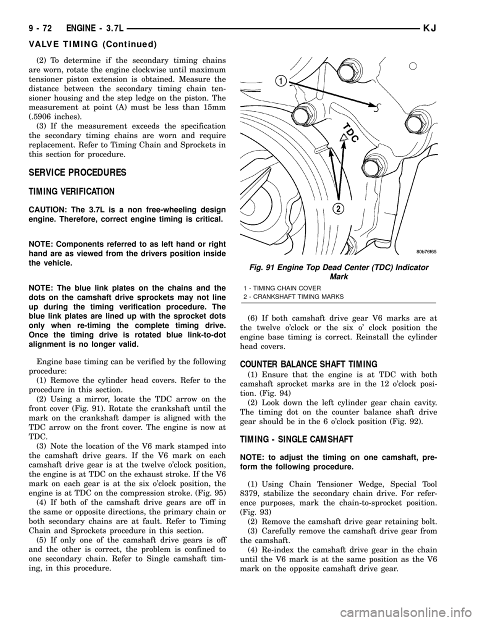
(2) Using a mirror, locate the TDC arrow on the
front cover (Fig. 91). Rotate the crankshaft until the
mark on the crankshaft damper is aligned with the
TDC arrow on the front cover. The engine is now at
TDC.
(3) Note the location of the V6 mark stamped into
the camshaft drive gears. If the V6 mark on each
camshaft drive gear is at the twelve o'clock position,
the engine is at TDC on the exhaust stroke. If the V6
mark on each gear is at the six o'clock position, the
engine is at TDC on the compression stroke. (Fig. 95)
(4) If both of the camshaft drive gears are off in
the same or opposite directions, the primary chain or
both secondary chains are at fault. Refer to Timing
Chain and Sprockets procedure in this section.
(5) If only one of the camshaft drive gears is off
and the other is correct, the problem is confined to
one secondary chain. Refer to Single camshaft tim-
ing, in this procedure.(6) If both camshaft drive gear V6 marks are at
the twelve o'clock or the six o' clock position the
engine base timing is correct. Reinstall the cylinder
head covers.
COUNTER BALANCE SHAFT TIMING
(1) Ensure that the engine is at TDC with both
camshaft sprocket marks are in the 12 o'clock posi-
tion. (Fig. 94)
(2) Look down the left cylinder gear chain cavity.
The timing dot on the counter balance shaft drive
gear should be in the 6 o'clock position (Fig. 92).
TIMING - SINGLE CAMSHAFT
NOTE: to adjust the timing on one camshaft, pre-
form the following procedure.
(1) Using Chain Tensioner Wedge, Special Tool
8379, stabilize the secondary chain drive. For refer-
ence purposes, mark the chain-to-sprocket position.
(Fig. 93)
(2) Remove the camshaft drive gear retaining bolt.
(3) Carefully remove the camshaft drive gear from
the camshaft.
(4) Re-index the camshaft drive gear in the chain
until the V6 mark is at the same position as the V6
mark on the opposite camshaft drive gear.
Fig. 91 Engine Top Dead Center (TDC) Indicator
Mark
1 - TIMING CHAIN COVER
2 - CRANKSHAFT TIMING MARKS
9 - 72 ENGINE - 3.7LKJ
VALVE TIMING (Continued)
Page 1409 of 1803
(14) Continue lowering tank while guiding remain-
ing hoses and lines.
(15) If fuel tank is to be replaced, remove LDP,
fuel filter and fuel pump module from tank. Refer to
Leak Detection Pump, Fuel Filter and Fuel Pump
Module Removal/Installation procedures.
INSTALLATION
(1) If fuel tank is to be replaced, install LDP, fuel
filter and fuel pump module to tank. Refer to Leak
Detection Pump, Fuel Filter and Fuel Pump Module
Removal/Installation procedures.
(2) Position fuel tank to hydraulic jack.
(3) Raise tank while carefully guiding vent tubes/
hoses through frame rail and crossmember. Before
tank reaches body, connect electrical connector to
Leak Detection Pump (LDP).
(4) Continue raising tank until positioned to body.
(5) Attach two fuel tank mounting straps and 4
mounting bolts. Tighten bolts to 61 N´m (45 ft. lbs.)
torque.
(6) Connect 2 hoses to body retention clip at left/
front of tank.
(7) Connect fuel filter fuel line to main fuel line
(snaps together). After connecting, snap this line into
body retention clip. Also connect LDP vacuum hose
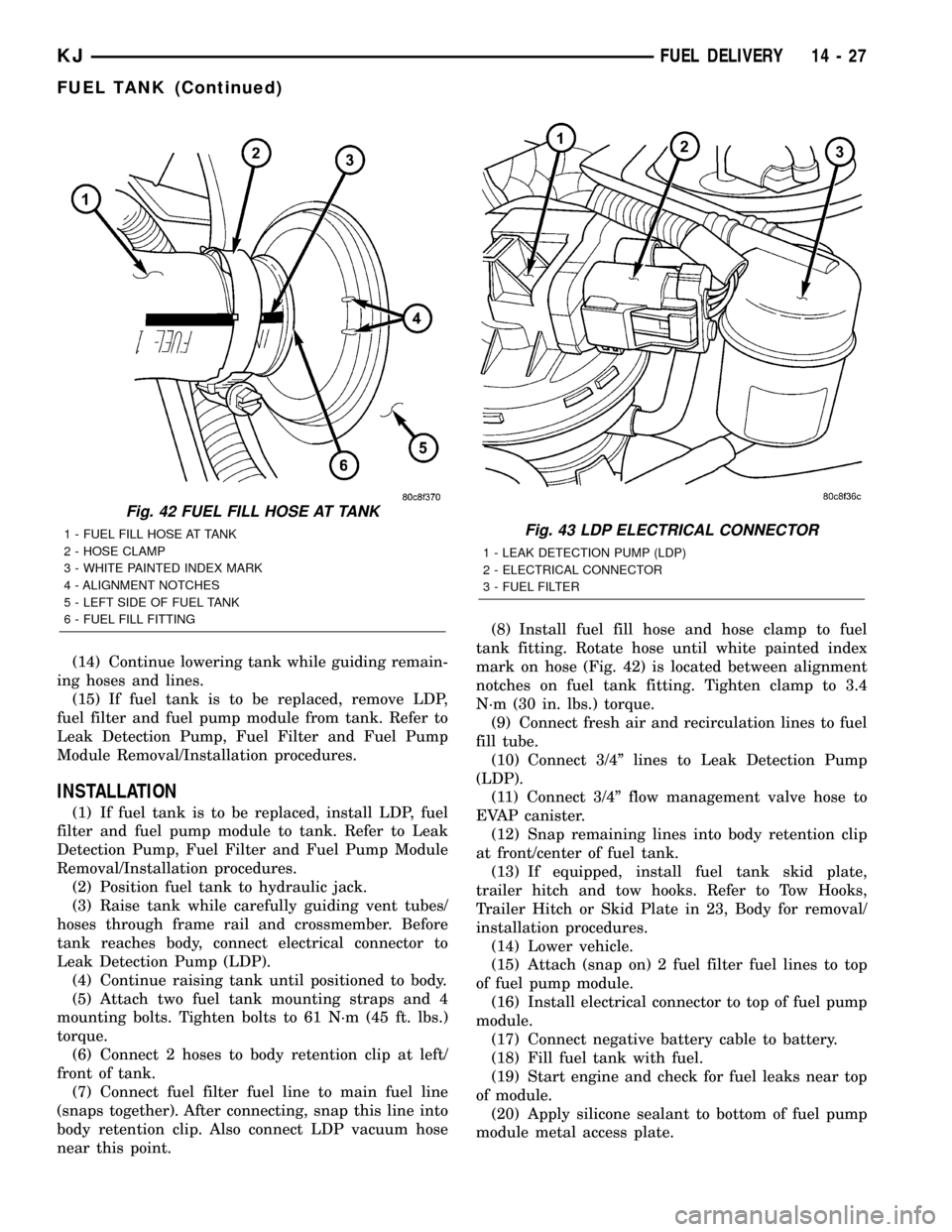
near this point.(8) Install fuel fill hose and hose clamp to fuel
tank fitting. Rotate hose until white painted index
mark on hose (Fig. 42) is located between alignment
notches on fuel tank fitting. Tighten clamp to 3.4
N´m (30 in. lbs.) torque.
(9) Connect fresh air and recirculation lines to fuel
fill tube.
(10) Connect 3/4º lines to Leak Detection Pump
(LDP).
(11) Connect 3/4º flow management valve hose to
EVAP canister.
(12) Snap remaining lines into body retention clip
at front/center of fuel tank.
(13) If equipped, install fuel tank skid plate,
trailer hitch and tow hooks. Refer to Tow Hooks,
Trailer Hitch or Skid Plate in 23, Body for removal/
installation procedures.
(14) Lower vehicle.
(15) Attach (snap on) 2 fuel filter fuel lines to top
of fuel pump module.
(16) Install electrical connector to top of fuel pump
module.
(17) Connect negative battery cable to battery.
(18) Fill fuel tank with fuel.
(19) Start engine and check for fuel leaks near top
of module.
(20) Apply silicone sealant to bottom of fuel pump
module metal access plate.
Fig. 42 FUEL FILL HOSE AT TANK
1 - FUEL FILL HOSE AT TANK
2 - HOSE CLAMP
3 - WHITE PAINTED INDEX MARK
4 - ALIGNMENT NOTCHES
5 - LEFT SIDE OF FUEL TANK
6 - FUEL FILL FITTINGFig. 43 LDP ELECTRICAL CONNECTOR
1 - LEAK DETECTION PUMP (LDP)
2 - ELECTRICAL CONNECTOR
3 - FUEL FILTER
KJFUEL DELIVERY 14 - 27
FUEL TANK (Continued)
Page 1471 of 1803
BODY STRUCTURE
TABLE OF CONTENTS
page page
ASSEMBLY
SPECIFICATIONS
SPECIFICATION.......................6
WELD AND STRUCTURAL ADHESIVE
LOCATIONS
SPECIFICATIONS........................9SEALER LOCATIONS
SPECIFICATIONS.......................87
OPENING DIMENSIONS
SPECIFICATIONS......................111
GAP AND FLUSH
SPECIFICATIONS......................116
ASSEMBLY
SPECIFICATIONS
SPECIFICATION
INDEX
DESCRIPTION FIGURE
COMPLETE BODY STRUCTURE VIEWS ( 1 )
BODY STRUCTURE - SECTIONS ( 2 )
23 - 6 BODY STRUCTUREKJ
Page 1475 of 1803
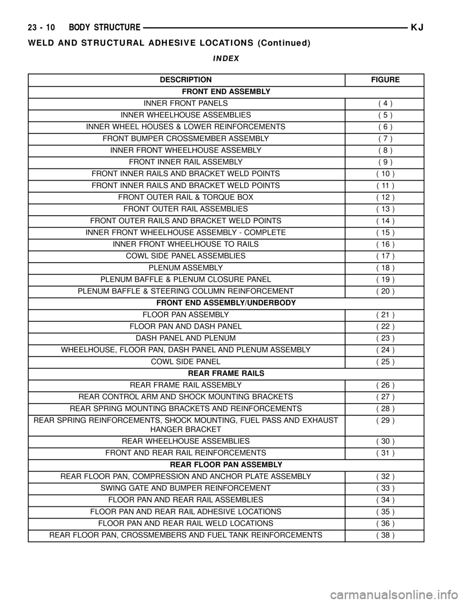
INDEX
DESCRIPTION FIGURE
FRONT END ASSEMBLY
INNER FRONT PANELS ( 4 )
INNER WHEELHOUSE ASSEMBLIES ( 5 )
INNER WHEEL HOUSES & LOWER REINFORCEMENTS ( 6 )
FRONT BUMPER CROSSMEMBER ASSEMBLY ( 7 )
INNER FRONT WHEELHOUSE ASSEMBLY ( 8 )
FRONT INNER RAIL ASSEMBLY ( 9 )
FRONT INNER RAILS AND BRACKET WELD POINTS ( 10 )
FRONT INNER RAILS AND BRACKET WELD POINTS ( 11 )
FRONT OUTER RAIL & TORQUE BOX ( 12 )
FRONT OUTER RAIL ASSEMBLIES ( 13 )
FRONT OUTER RAILS AND BRACKET WELD POINTS ( 14 )
INNER FRONT WHEELHOUSE ASSEMBLY - COMPLETE ( 15 )
INNER FRONT WHEELHOUSE TO RAILS ( 16 )
COWL SIDE PANEL ASSEMBLIES ( 17 )
PLENUM ASSEMBLY ( 18 )
PLENUM BAFFLE & PLENUM CLOSURE PANEL ( 19 )
PLENUM BAFFLE & STEERING COLUMN REINFORCEMENT ( 20 )
FRONT END ASSEMBLY/UNDERBODY
FLOOR PAN ASSEMBLY ( 21 )
FLOOR PAN AND DASH PANEL ( 22 )
DASH PANEL AND PLENUM ( 23 )
WHEELHOUSE, FLOOR PAN, DASH PANEL AND PLENUM ASSEMBLY ( 24 )
COWL SIDE PANEL ( 25 )
REAR FRAME RAILS
REAR FRAME RAIL ASSEMBLY ( 26 )
REAR CONTROL ARM AND SHOCK MOUNTING BRACKETS ( 27 )
REAR SPRING MOUNTING BRACKETS AND REINFORCEMENTS ( 28 )
REAR SPRING REINFORCEMENTS, SHOCK MOUNTING, FUEL PASS AND EXHAUST
HANGER BRACKET(29)
REAR WHEELHOUSE ASSEMBLIES ( 30 )
FRONT AND REAR RAIL REINFORCEMENTS ( 31 )
REAR FLOOR PAN ASSEMBLY
REAR FLOOR PAN, COMPRESSION AND ANCHOR PLATE ASSEMBLY ( 32 )
SWING GATE AND BUMPER REINFORCEMENT ( 33 )
FLOOR PAN AND REAR RAIL ASSEMBLIES ( 34 )
FLOOR PAN AND REAR RAIL ADHESIVE LOCATIONS ( 35 )
FLOOR PAN AND REAR RAIL WELD LOCATIONS ( 36 )
REAR FLOOR PAN, CROSSMEMBERS AND FUEL TANK REINFORCEMENTS ( 38 )
23 - 10 BODY STRUCTUREKJ
WELD AND STRUCTURAL ADHESIVE LOCATIONS (Continued)
Page 1552 of 1803
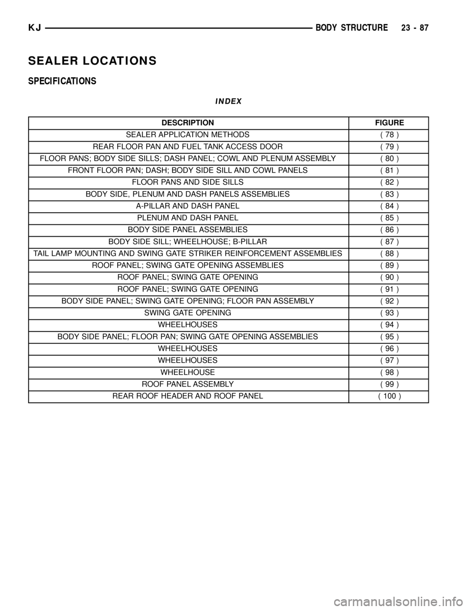
SEALER LOCATIONS
SPECIFICATIONS
INDEX
DESCRIPTION FIGURE
SEALER APPLICATION METHODS ( 78 )
REAR FLOOR PAN AND FUEL TANK ACCESS DOOR ( 79 )
FLOOR PANS; BODY SIDE SILLS; DASH PANEL; COWL AND PLENUM ASSEMBLY ( 80 )
FRONT FLOOR PAN; DASH; BODY SIDE SILL AND COWL PANELS ( 81 )
FLOOR PANS AND SIDE SILLS ( 82 )
BODY SIDE, PLENUM AND DASH PANELS ASSEMBLIES ( 83 )
A-PILLAR AND DASH PANEL ( 84 )
PLENUM AND DASH PANEL ( 85 )
BODY SIDE PANEL ASSEMBLIES ( 86 )
BODY SIDE SILL; WHEELHOUSE; B-PILLAR ( 87 )
TAIL LAMP MOUNTING AND SWING GATE STRIKER REINFORCEMENT ASSEMBLIES ( 88 )
ROOF PANEL; SWING GATE OPENING ASSEMBLIES ( 89 )
ROOF PANEL; SWING GATE OPENING ( 90 )
ROOF PANEL; SWING GATE OPENING ( 91 )
BODY SIDE PANEL; SWING GATE OPENING; FLOOR PAN ASSEMBLY ( 92 )
SWING GATE OPENING ( 93 )
WHEELHOUSES ( 94 )
BODY SIDE PANEL; FLOOR PAN; SWING GATE OPENING ASSEMBLIES ( 95 )
WHEELHOUSES ( 96 )
WHEELHOUSES ( 97 )
WHEELHOUSE ( 98 )
ROOF PANEL ASSEMBLY ( 99 )
REAR ROOF HEADER AND ROOF PANEL ( 100 )
KJBODY STRUCTURE 23 - 87
Page 1576 of 1803
OPENING DIMENSIONS
SPECIFICATIONS
INDEX
DESCRIPTION FIGURE
ENGINE COMPARTMENT ( 101 )
WINDSHIELD OPENING ( 102 )
BODY SIDE OPENINGS ( 103 )
SWING GATE OPENING ( 104 )
KJBODY STRUCTURE 23 - 111
Page 1581 of 1803
GAP AND FLUSH
SPECIFICATIONS
GAP & FLUSH DIMENSIONS INDEX
DESCRIPTION FIGURE
FRONT QUADRANT ( 105 )
REAR QUADRANT ( 106 )
23 - 116 BODY STRUCTUREKJ