2002 JEEP LIBERTY torque
[x] Cancel search: torquePage 1469 of 1803
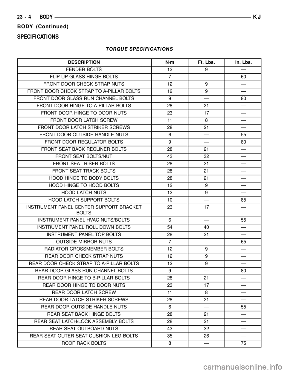
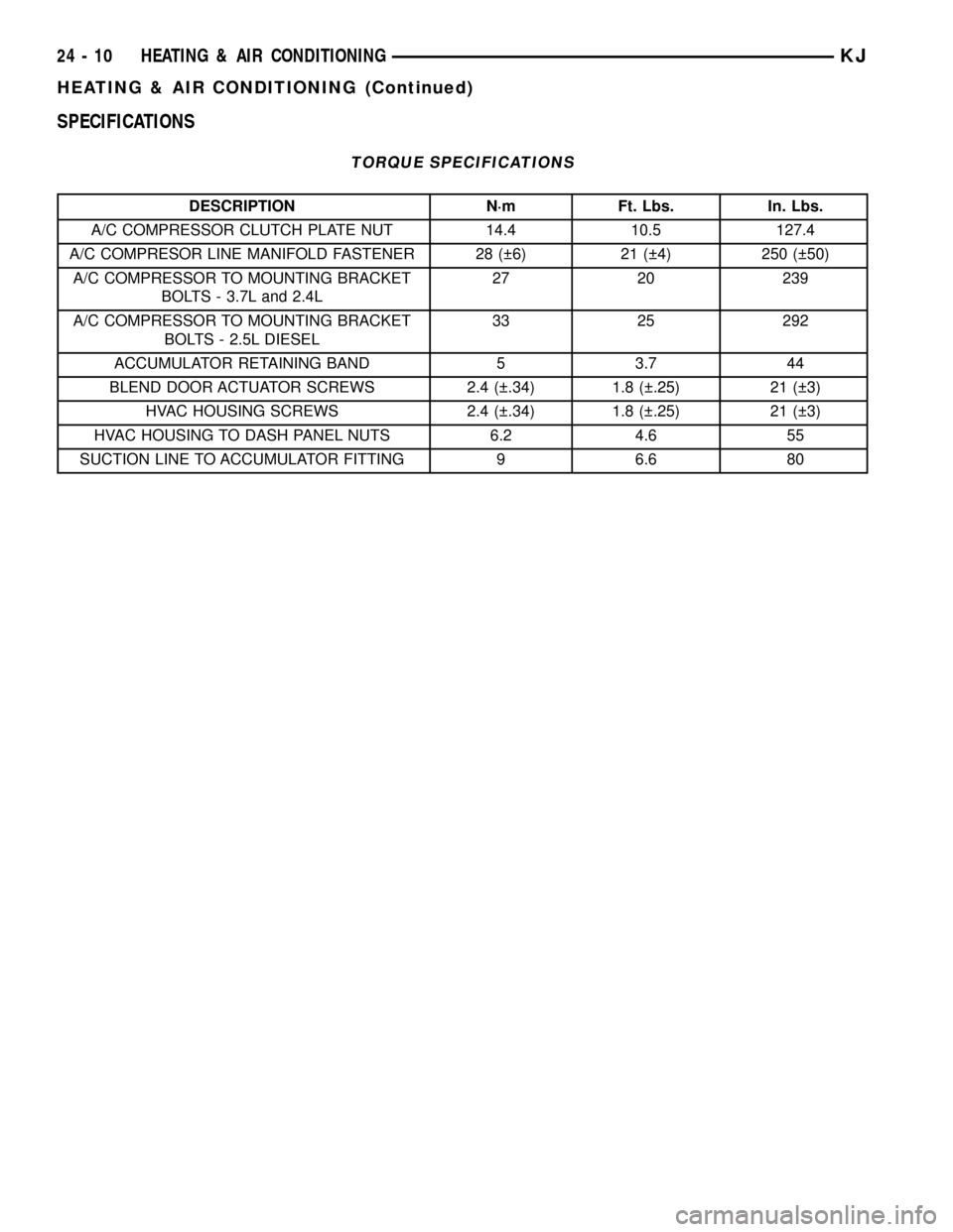
SPECIFICATIONS
TORQUE SPECIFICATIONS
DESCRIPTION N´m Ft. Lbs. In. Lbs.
FENDER BOLTS 12 9 Ð
FLIP-UP GLASS HINGE BOLTS 7 Ð 60
FRONT DOOR CHECK STRAP NUTS 12 9 Ð
FRONT DOOR CHECK STRAP TO A-PILLAR BOLTS 12 9 Ð
FRONT DOOR GLASS RUN CHANNEL BOLTS 9 Ð 80
FRONT DOOR HINGE TO A-PILLAR BOLTS 28 21 Ð
FRONT DOOR HINGE TO DOOR NUTS 23 17 Ð
FRONT DOOR LATCH SCREW 11 8 Ð
FRONT DOOR LATCH STRIKER SCREWS 28 21 Ð
FRONT DOOR OUTSIDE HANDLE NUTS 6 Ð 55
FRONT DOOR REGULATOR BOLTS 9 Ð 80
FRONT SEAT BACK RECLINER BOLTS 28 21 Ð
FRONT SEAT BOLTS/NUT 43 32 Ð
FRONT SEAT RISER BOLTS 28 21 Ð
FRONT SEAT TRACK BOLTS 28 21 Ð
HOOD HINGE TO BODY BOLTS 28 21 Ð
HOOD HINGE TO HOOD BOLTS 12 9 Ð
HOOD LATCH NUTS 12 9 Ð
HOOD LATCH SUPPORT BOLTS 10 Ð 85
INSTRUMENT PANEL CENTER SUPPORT BRACKET
BOLTS23 17 Ð
INSTRUMENT PANEL HVAC NUTS/BOLTS 6 Ð 55
INSTRUMENT PANEL ROLL DOWN BOLTS 54 40 Ð
INSTRUMENT PANEL TOP BOLTS 28 21 Ð
OUTSIDE MIRROR NUTS 7 Ð 65
RADIATOR CROSSMEMBER BOLTS 12 9 Ð
REAR DOOR CHECK STRAP NUTS 12 9 Ð
REAR DOOR CHECK STRAP TO A-PILLAR BOLTS 12 9 Ð
REAR DOOR GLASS RUN CHANNEL BOLTS 9 Ð 80
REAR DOOR HINGE TO B-PILLAR BOLTS 28 21 Ð
REAR DOOR HINGE TO DOOR NUTS 23 17 Ð
REAR DOOR LATCH SCREW 11 8 Ð
REAR DOOR LATCH STRIKER SCREWS 28 21 Ð
REAR DOOR OUTSIDE HANDLE NUTS 6 Ð 55
REAR SEAT BACK HINGE BOLTS 28 21 Ð
REAR SEAT LATCH/LOCK ASSEMBLY BOLTS 28 21 Ð
REAR SEAT OUTBOARD NUTS 43 32 Ð
REAR SEAT OUTER SEAT CUSHION LEG BOLTS 35 26 Ð
ROOF RACK BOLTS 8 Ð 75
23 - 4 BODYKJ
BODY (Continued)
Page 1475 of 1803
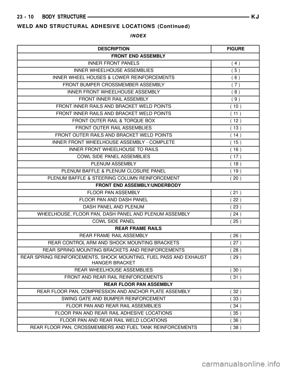
INDEX
DESCRIPTION FIGURE
FRONT END ASSEMBLY
INNER FRONT PANELS ( 4 )
INNER WHEELHOUSE ASSEMBLIES ( 5 )
INNER WHEEL HOUSES & LOWER REINFORCEMENTS ( 6 )
FRONT BUMPER CROSSMEMBER ASSEMBLY ( 7 )
INNER FRONT WHEELHOUSE ASSEMBLY ( 8 )
FRONT INNER RAIL ASSEMBLY ( 9 )
FRONT INNER RAILS AND BRACKET WELD POINTS ( 10 )
FRONT INNER RAILS AND BRACKET WELD POINTS ( 11 )
FRONT OUTER RAIL & TORQUE BOX ( 12 )
FRONT OUTER RAIL ASSEMBLIES ( 13 )
FRONT OUTER RAILS AND BRACKET WELD POINTS ( 14 )
INNER FRONT WHEELHOUSE ASSEMBLY - COMPLETE ( 15 )
INNER FRONT WHEELHOUSE TO RAILS ( 16 )
COWL SIDE PANEL ASSEMBLIES ( 17 )
PLENUM ASSEMBLY ( 18 )
PLENUM BAFFLE & PLENUM CLOSURE PANEL ( 19 )
PLENUM BAFFLE & STEERING COLUMN REINFORCEMENT ( 20 )
FRONT END ASSEMBLY/UNDERBODY
FLOOR PAN ASSEMBLY ( 21 )
FLOOR PAN AND DASH PANEL ( 22 )
DASH PANEL AND PLENUM ( 23 )
WHEELHOUSE, FLOOR PAN, DASH PANEL AND PLENUM ASSEMBLY ( 24 )
COWL SIDE PANEL ( 25 )
REAR FRAME RAILS
REAR FRAME RAIL ASSEMBLY ( 26 )
REAR CONTROL ARM AND SHOCK MOUNTING BRACKETS ( 27 )
REAR SPRING MOUNTING BRACKETS AND REINFORCEMENTS ( 28 )
REAR SPRING REINFORCEMENTS, SHOCK MOUNTING, FUEL PASS AND EXHAUST
HANGER BRACKET(29)
REAR WHEELHOUSE ASSEMBLIES ( 30 )
FRONT AND REAR RAIL REINFORCEMENTS ( 31 )
REAR FLOOR PAN ASSEMBLY
REAR FLOOR PAN, COMPRESSION AND ANCHOR PLATE ASSEMBLY ( 32 )
SWING GATE AND BUMPER REINFORCEMENT ( 33 )
FLOOR PAN AND REAR RAIL ASSEMBLIES ( 34 )
FLOOR PAN AND REAR RAIL ADHESIVE LOCATIONS ( 35 )
FLOOR PAN AND REAR RAIL WELD LOCATIONS ( 36 )
REAR FLOOR PAN, CROSSMEMBERS AND FUEL TANK REINFORCEMENTS ( 38 )
23 - 10 BODY STRUCTUREKJ
WELD AND STRUCTURAL ADHESIVE LOCATIONS (Continued)
Page 1626 of 1803
REAR VIEW MIRROR
REMOVAL
(1) If equipped, disconnect mirror harness connec-
tor.
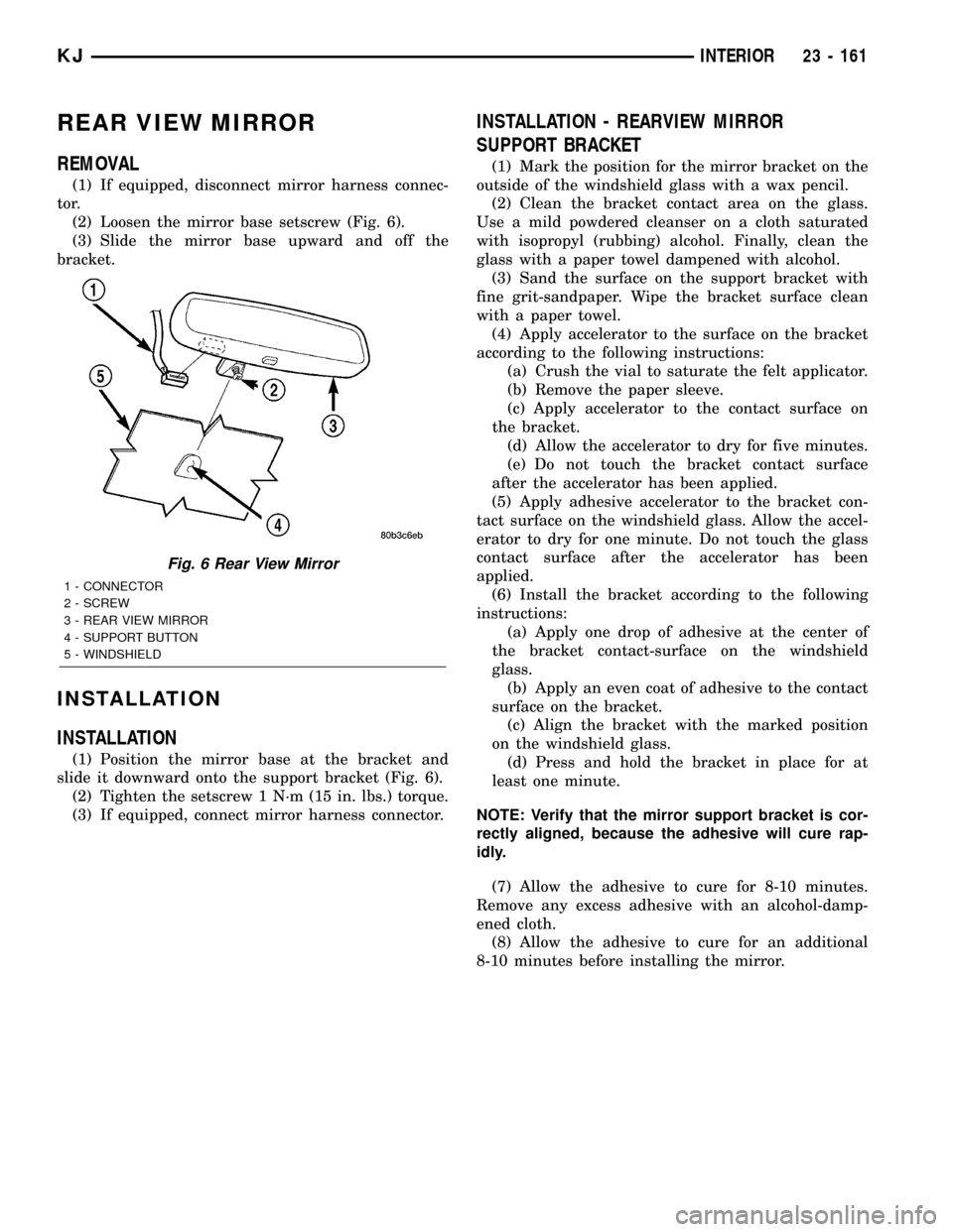
(2) Loosen the mirror base setscrew (Fig. 6).
(3) Slide the mirror base upward and off the
bracket.
INSTALLATION
INSTALLATION
(1) Position the mirror base at the bracket and
slide it downward onto the support bracket (Fig. 6).
(2) Tighten the setscrew 1 N´m (15 in. lbs.) torque.
(3) If equipped, connect mirror harness connector.
INSTALLATION - REARVIEW MIRROR
SUPPORT BRACKET
(1) Mark the position for the mirror bracket on the
outside of the windshield glass with a wax pencil.
(2) Clean the bracket contact area on the glass.
Use a mild powdered cleanser on a cloth saturated
with isopropyl (rubbing) alcohol. Finally, clean the
glass with a paper towel dampened with alcohol.
(3) Sand the surface on the support bracket with
fine grit-sandpaper. Wipe the bracket surface clean
with a paper towel.
(4) Apply accelerator to the surface on the bracket
according to the following instructions:
(a) Crush the vial to saturate the felt applicator.
(b) Remove the paper sleeve.
(c) Apply accelerator to the contact surface on
the bracket.
(d) Allow the accelerator to dry for five minutes.
(e) Do not touch the bracket contact surface
after the accelerator has been applied.
(5) Apply adhesive accelerator to the bracket con-
tact surface on the windshield glass. Allow the accel-
erator to dry for one minute. Do not touch the glass
contact surface after the accelerator has been
applied.
(6) Install the bracket according to the following
instructions:
(a) Apply one drop of adhesive at the center of
the bracket contact-surface on the windshield
glass.
(b) Apply an even coat of adhesive to the contact
surface on the bracket.
(c) Align the bracket with the marked position
on the windshield glass.
(d) Press and hold the bracket in place for at
least one minute.
NOTE: Verify that the mirror support bracket is cor-
rectly aligned, because the adhesive will cure rap-
idly.
(7) Allow the adhesive to cure for 8-10 minutes.
Remove any excess adhesive with an alcohol-damp-
ened cloth.
(8) Allow the adhesive to cure for an additional
8-10 minutes before installing the mirror.
Fig. 6 Rear View Mirror
1 - CONNECTOR
2 - SCREW
3 - REAR VIEW MIRROR
4 - SUPPORT BUTTON
5 - WINDSHIELD
KJINTERIOR 23 - 161
Page 1648 of 1803
(4) Test sunroof operation, adjust as necessary.
(5) Install headliner. (Refer to 23 - BODY/INTERI-
OR/HEADLINER - INSTALLATION)
CONTROL MODULE
REMOVAL
(1) Remove the module assembly. (Refer to 23 -
BODY/SUNROOF/MODULE ASSEMBLY -
REMOVAL)
(2) Remove three motor assembly retaining screws
from bottom side of motor, and remove motor assem-
bly (Fig. 11).
(3) From top side of module assembly, remove one
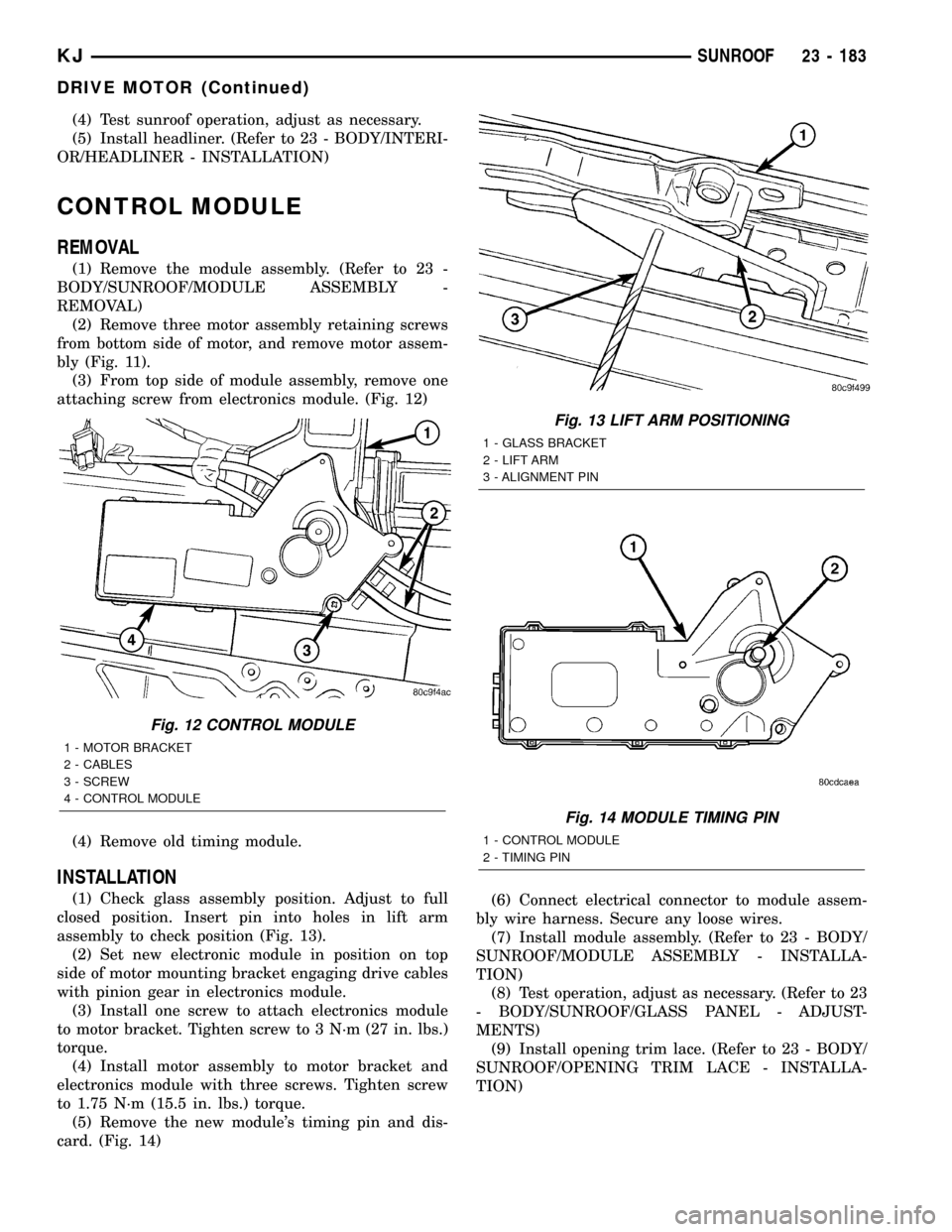
attaching screw from electronics module. (Fig. 12)
(4) Remove old timing module.
INSTALLATION
(1) Check glass assembly position. Adjust to full
closed position. Insert pin into holes in lift arm
assembly to check position (Fig. 13).
(2) Set new electronic module in position on top
side of motor mounting bracket engaging drive cables
with pinion gear in electronics module.
(3) Install one screw to attach electronics module
to motor bracket. Tighten screw to 3 N´m (27 in. lbs.)
torque.
(4) Install motor assembly to motor bracket and
electronics module with three screws. Tighten screw
to 1.75 N´m (15.5 in. lbs.) torque.
(5) Remove the new module's timing pin and dis-
card. (Fig. 14)(6) Connect electrical connector to module assem-
bly wire harness. Secure any loose wires.
(7) Install module assembly. (Refer to 23 - BODY/
SUNROOF/MODULE ASSEMBLY - INSTALLA-
TION)
(8) Test operation, adjust as necessary. (Refer to 23
- BODY/SUNROOF/GLASS PANEL - ADJUST-
MENTS)
(9) Install opening trim lace. (Refer to 23 - BODY/
SUNROOF/OPENING TRIM LACE - INSTALLA-
TION)
Fig. 12 CONTROL MODULE
1 - MOTOR BRACKET
2 - CABLES
3 - SCREW
4 - CONTROL MODULE
Fig. 13 LIFT ARM POSITIONING
1 - GLASS BRACKET
2 - LIFT ARM
3 - ALIGNMENT PIN
Fig. 14 MODULE TIMING PIN
1 - CONTROL MODULE
2 - TIMING PIN
KJSUNROOF 23 - 183
DRIVE MOTOR (Continued)
Page 1662 of 1803
SPECIFICATIONS
TORQUE SPECIFICATIONS
DESCRIPTION N´m Ft. Lbs. In. Lbs.
A/C COMPRESSOR CLUTCH PLATE NUT 14.4 10.5 127.4
A/C COMPRESOR LINE MANIFOLD FASTENER 28 ( 6) 21 ( 4) 250 ( 50)
A/C COMPRESSOR TO MOUNTING BRACKET
BOLTS - 3.7L and 2.4L27 20 239
A/C COMPRESSOR TO MOUNTING BRACKET
BOLTS - 2.5L DIESEL33 25 292
ACCUMULATOR RETAINING BAND 5 3.7 44
BLEND DOOR ACTUATOR SCREWS 2.4 ( .34) 1.8 ( .25) 21 ( 3)
HVAC HOUSING SCREWS 2.4 ( .34) 1.8 ( .25) 21 ( 3)
HVAC HOUSING TO DASH PANEL NUTS 6.2 4.6 55
SUCTION LINE TO ACCUMULATOR FITTING 9 6.6 80
24 - 10 HEATING & AIR CONDITIONINGKJ
HEATING & AIR CONDITIONING (Continued)
Page 1665 of 1803
to 2000 rpm. This procedure (burnishing) will seat
the opposing friction surfaces and provide a higher
compressor clutch torque capability.
REMOVAL
The refrigerant system can remain fully-charged
during compressor clutch, rotor, or coil replacement.
The compressor clutch can be serviced in the vehicle.
(1) Disconnect and isolate the battery negative
cable.
(2) Remove the serpentine drive belt(Refer to 7 -
COOLING/ACCESSORY DRIVE/DRIVE BELTS -
REMOVAL).
(3) Unplug the compressor clutch coil wire harness
connector.
(4) Remove the four bolts that secure the compres-
sor to the mounting bracket.
(5) Remove the compressor from the mounting
bracket. Support the compressor in the engine com-
partment while servicing the clutch.
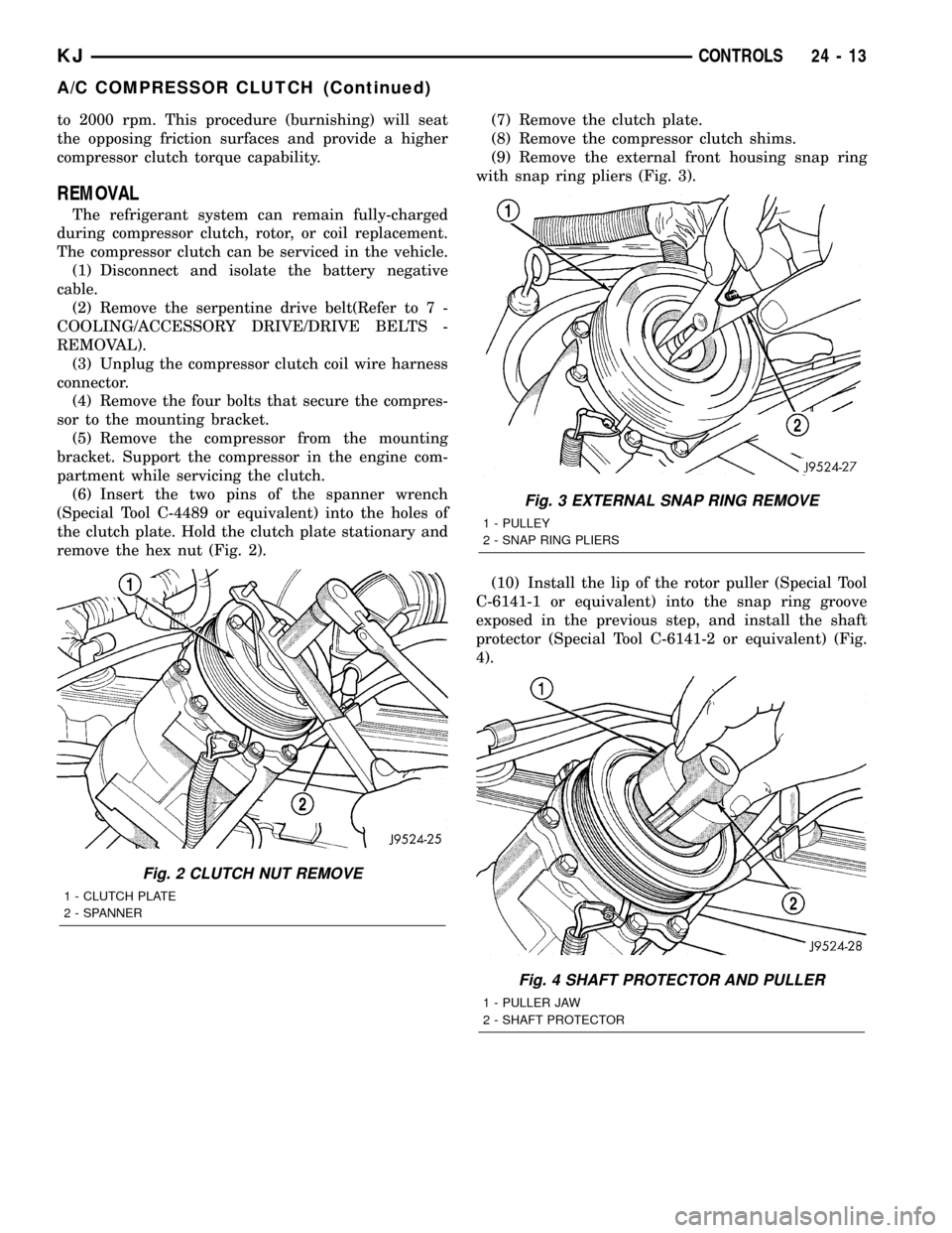
(6) Insert the two pins of the spanner wrench
(Special Tool C-4489 or equivalent) into the holes of
the clutch plate. Hold the clutch plate stationary and
remove the hex nut (Fig. 2).(7) Remove the clutch plate.
(8) Remove the compressor clutch shims.
(9) Remove the external front housing snap ring
with snap ring pliers (Fig. 3).
(10) Install the lip of the rotor puller (Special Tool
C-6141-1 or equivalent) into the snap ring groove
exposed in the previous step, and install the shaft
protector (Special Tool C-6141-2 or equivalent) (Fig.
4).
Fig. 2 CLUTCH NUT REMOVE
1 - CLUTCH PLATE
2 - SPANNER
Fig. 3 EXTERNAL SNAP RING REMOVE
1 - PULLEY
2 - SNAP RING PLIERS
Fig. 4 SHAFT PROTECTOR AND PULLER
1 - PULLER JAW
2 - SHAFT PROTECTOR
KJCONTROLS 24 - 13
A/C COMPRESSOR CLUTCH (Continued)
Page 1691 of 1803

In addition, the flexible hose refrigerant lines should
be routed so they are at least 80 millimeters (3
inches) from an exhaust manifold.
WARNING
SERVICE WARNINGS
WARNING: THE AIR CONDITIONING SYSTEM CON-
TAINS REFRIGERANT UNDER HIGH PRESSURE.
SEVERE PERSONAL INJURY MAY RESULT FROM
IMPROPER SERVICE PROCEDURES. REPAIRS
SHOULD ONLY BE PERFORMED BY QUALIFIED SER-
VICE PERSONNEL.
AVOID BREATHING THE REFRIGERANT AND REFRIG-
ERANT OIL VAPOR OR MIST. EXPOSURE MAY IRRI-
TATE THE EYES, NOSE, AND/OR THROAT. WEAR EYE
PROTECTION WHEN SERVICING THE AIR CONDITION-
ING REFRIGERANT SYSTEM. SERIOUS EYE INJURY
CAN RESULT FROM DIRECT CONTACT WITH THE
REFRIGERANT. IF EYE CONTACT OCCURS, SEEK
MEDICAL ATTENTION IMMEDIATELY.
DO NOT EXPOSE THE REFRIGERANT TO OPEN
FLAME. POISONOUS GAS IS CREATED WHEN
REFRIGERANT IS BURNED. AN ELECTRONIC LEAK
DETECTOR IS RECOMMENDED.
IF ACCIDENTAL SYSTEM DISCHARGE OCCURS, VEN-
TILATE THE WORK AREA BEFORE RESUMING SER-
VICE. LARGE AMOUNTS OF REFRIGERANT
RELEASED IN A CLOSED WORK AREA WILL DIS-
PLACE THE OXYGEN AND CAUSE SUFFOCATION.
THE EVAPORATION RATE OF R-134a REFRIGERANT
AT AVERAGE TEMPERATURE AND ALTITUDE IS
EXTREMELY HIGH. AS A RESULT, ANYTHING THAT
COMES IN CONTACT WITH THE REFRIGERANT WILL
FREEZE. ALWAYS PROTECT THE SKIN OR DELICATE
OBJECTS FROM DIRECT CONTACT WITH THE
REFRIGERANT.
THE R-134a SERVICE EQUIPMENT OR THE VEHICLE
REFRIGERANT SYSTEM SHOULD NOT BE PRESSURE
TESTED OR LEAK TESTED WITH COMPRESSED AIR.
SOME MIXTURES OF AIR AND R-134a HAVE BEEN
SHOWN TO BE COMBUSTIBLE AT ELEVATED PRES-
SURES. THESE MIXTURES ARE POTENTIALLY DAN-
GEROUS, AND MAY RESULT IN FIRE OR EXPLOSION
CAUSING INJURY OR PROPERTY DAMAGE.
CAUTION
SERVICE CAUTIONS
CAUTION: Liquid refrigerant is corrosive to metal sur-
faces. Follow the operating instructions supplied with
the service equipment being used.Never add R-12 to a refrigerant system designed to
use R-134a. Damage to the system will result.
R-12 refrigerant oil must not be mixed with R-134a
refrigerant oil. They are not compatible.
Do not use R-12 equipment or parts on the R-134a
system. Damage to the system will result.
Do not overcharge the refrigerant system. This will
cause excessive compressor head pressure and can
cause noise and system failure.
Recover the refrigerant before opening any fitting or
connection. Open the fittings with caution, even after
the system has been discharged. Never open or
loosen a connection before recovering the refrigerant.
Do not remove the secondary retention clip from any
spring-lock coupler connection while the refrigerant
system is under pressure. Recover the refrigerant
before removing the secondary retention clip. Open
the fittings with caution, even after the system has
been discharged. Never open or loosen a connection
before recovering the refrigerant.
The refrigerant system must always be evacuated
before charging.
Do not open the refrigerant system or uncap a
replacement component until you are ready to service
the system. This will prevent contamination in the sys-
tem.
Before disconnecting a component, clean the outside
of the fittings thoroughly to prevent contamination
from entering the refrigerant system.
Immediately after disconnecting a component from the
refrigerant system, seal the open fittings with a cap or
plug.
Before connecting an open refrigerant fitting, always
install a new seal or gasket. Coat the fitting and seal
with clean refrigerant oil before connecting.
Do not remove the sealing caps from a replacement
component until it is to be installed.
When installing a refrigerant line, avoid sharp bends
that may restrict refrigerant flow. Position the refriger-
ant lines away from exhaust system components or
any sharp edges, which may damage the line.
Tighten refrigerant fittings only to the specified torque.
The aluminum fittings used in the refrigerant system
will not tolerate overtightening.
When disconnecting a refrigerant fitting, use a wrench
on both halves of the fitting. This will prevent twisting
of the refrigerant lines or tubes.
Refrigerant oil will absorb moisture from the atmo-
sphere if left uncapped. Do not open a container of
refrigerant oil until you are ready to use it. Replace the
cap on the oil container immediately after using. Store
refrigerant oil only in a clean, airtight, and moisture-
free container.
Keep service tools and the work area clean. Contami-
nation of the refrigerant system through careless work
habits must be avoided.
KJPLUMBING 24 - 39
PLUMBING (Continued)
Page 1696 of 1803
INSTALLATION
WARNING: REVIEW THE WARNINGS AND CAU-
TIONS IN THE FRONT OF THIS SECTION BEFORE
PERFORMING THE FOLLOWING OPERATION.
(Refer to 24 - HEATING & AIR CONDITIONING/
PLUMBING - WARNING) (Refer to 24 - HEATING &
AIR CONDITIONING/PLUMBING - CAUTION) (Refer
to 24 - HEATING & AIR CONDITIONING/PLUMBING -
CAUTION - REFRIGERANT HOSES/LINES/TUBES
PRECAUTIONS)
The compressor may be removed and repositioned
without disconnecting the refrigerant lines or dis-
charging the refrigerant system. Discharging is not
necessary if servicing the compressor clutch or clutch
coil, the engine, the cylinder head, or the generator.
NOTE: If a replacement compressor is being
installed, be certain to check the refrigerant oil
level. (Refer to 24 - HEATING & AIR CONDITIONING/
PLUMBING/REFRIGERANT OIL - STANDARD PRO-
CEDURE - REFRIGERANT OIL LEVEL) Use only
refrigerant oil of the type recommended for the
compressor in the vehicle. (Refer to 24 - HEATING &
AIR CONDITIONING/PLUMBING/REFRIGERANT OIL -
DESCRIPTION)(1) Install the compressor to the mounting bracket.
Tighten the three mounting bolts to 27 N´m (20 ft.
lbs.), (2.4L gasoline and 2.5L diesel engines only).
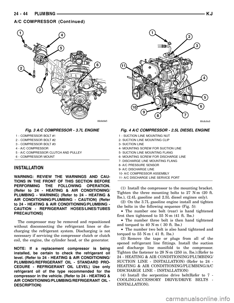
(2) On the 3.7L gasoline engine install and tighten
the bolts in the following sequence (Fig. 5):
²The number one bolt (rear) is hand tightened
first then tightened to 55 N´m (41 ft. lbs.)
²The number three bolt is then hand tightened
and torqued to 40 N´m ( 30 ft. lbs.)
²The number two bolt is also hand tightened and
torqued to 55 N´m ( 41 ft. lbs.)
(3) Remove the tape or plugs from all of the
opened refrigerant line fittings. Install the suction
and discharge line manifold to the compressor.
Tighten the fastener to 28 N´m (250 in. lbs.).(Refer to
24 - HEATING & AIR CONDITIONING/PLUMBING/
SUCTION LINE - INSTALLATION) (Refer to 24 -
HEATING & AIR CONDITIONING/PLUMBING/A/C
DISCHARGE LINE - INSTALLATION)
(4) Install the serpentine drive belt(Refer to 7 -
COOLING/ACCESSORY DRIVE/DRIVE BELTS -
INSTALLATION).
Fig. 3 A/C COMPRESSOR - 3.7L ENGINE
1 - COMPRESSOR BOLT #1
2 - COMPRESSOR BOLT #2
3 - COMPRESSOR BOLT #3
4 - A/C COMPRESSOR
5 - A/C COMPRESSOR CLUTCH AND PULLEY
6 - COMPRESSOR MOUNT
Fig. 4 A/C COMPRESSOR - 2.5L DIESEL ENGINE
1 - SUCTION LINE MOUNTING NUT
2- SUCTION LINE MOUNTING CLIP
3- SUCTION LINE
4- MOUNTING SCREW FOR SUCTION LINE
5- SUCTION LINE MOUNTING FLANG
6- MOUNTING SCREW FOR DISCHARGE LINE
7- DISCHARGE LINE MOUNTING FLANG
8- A/C PRESSURE SENSOR
9- A/C DISCHARGE LINE
10- A/C COMPRESSOR ASSEMBLY
11- A/C DISCHARGE LINE SERVICE PORT
24 - 44 PLUMBINGKJ
A/C COMPRESSOR (Continued)