2002 JEEP LIBERTY Egr
[x] Cancel search: EgrPage 1406 of 1803
(14) If fuel injectors are to be removed, refer to
Fuel Injector Removal/Installation.
INSTALLATION
2.4L Engine
(1) If fuel injectors are to be installed, refer to Fuel
Injector Removal/Installation.
(2) Clean out fuel injector machined bores in
intake manifold.
(3) Apply a small amount of engine oil to each fuel
injector o-ring. This will help in fuel rail installation.
(4) Position fuel rail/fuel injector assembly to
machined injector openings in intake manifold.
(5) Guide each injector into cylinder head. Be care-
ful not to tear injector o-rings.
(6) Push fuel rail down until fuel injectors have
bottomed on shoulders.
(7) Install 2 fuel rail mounting bolts and tighten.
Refer to torque specifications.
(8) Connect electrical connectors at all fuel injec-
tors. To install connector, refer to (Fig. 37). Push con-
nector onto injector (1) and then push and lock red
colored slider (2). Verify connector is locked to injec-
tor by lightly tugging on connector.
(9) Snap 2 injection wiring harness clips (Fig. 35)
into brackets.
(10) Connect 2 main engine harness connectors at
rear of intake manifold (Fig. 34).
(11) Tighten 5 intake manifold mounting bolts.
Refer to Engine Torque Specifications.
(12) Install PCV valve and hose.
(13) Install thermostat and radiator hose. Fill with
coolant. Refer to Cooling.
(14) Connect necessary vacuum lines to throttle
body.
(15) Connect fuel line latch clip and fuel line to
fuel rail. Refer to Quick-Connect Fittings.
(16) Install air duct to throttle body.
(17) Connect battery cable to battery.
(18) Start engine and check for leaks.
3.7L Engine
(1) If fuel injectors are to be installed, refer to Fuel
Injector Removal/Installation.
(2) Clean out fuel injector machined bores in
intake manifold.
(3) Apply a small amount of engine oil to each fuel
injector o-ring. This will help in fuel rail installation.
(4) Position fuel rail/fuel injector assembly to
machined injector openings in cylinder head.
(5) Guide each injector into cylinder head. Be care-
ful not to tear injector o-rings.
(6) Pushrightside of fuel rail down until fuel
injectors have bottomed on cylinder head shoulder.Pushleftfuel rail down until injectors have bot-
tomed on cylinder head shoulder.
(7) Install 4 fuel rail mounting bolts and tighten.
Refer to torque specifications.
(8) Install 6 ignition coils. Refer to Ignition Coil
Removal/Installation.
(9) Connect electrical connectors to throttle body.
(10) Connect electrical connectors at all fuel injec-
tors. To install connector, refer to (Fig. 37). Push con-
nector onto injector (1) and then push and lock red
colored slider (2). Verify connector is locked to injec-
tor by lightly tugging on connector.
(11) Connect necessary vacuum lines to throttle
body.
(12) Connect fuel line latch clip and fuel line to
fuel rail. Refer to Quick-Connect Fittings.
(13) Install air box to throttle body.
(14) Install air duct to air box.
(15) Connect battery cable to battery.
(16) Start engine and check for leaks.
FUEL TANK
DESCRIPTION
The fuel tank is constructed of a plastic material.
Its main functions are for fuel storage and for place-
ment of the fuel pump module, and certain ORVR
components.
OPERATION
All models pass a full 360 degree rollover test
without fuel leakage. To accomplish this, fuel and
vapor flow controls are required for all fuel tank con-
nections.
A check (control) valve is mounted into the top sec-
tion of the 2±piece fuel pump module. Refer to Fuel
Tank Check Valve for additional information.
An evaporation control system is connected to the
fuel tank to reduce emissions of fuel vapors into the
atmosphere. When fuel evaporates from the fuel
tank, vapors pass through vent hoses or tubes to a
charcoal canister where they are temporarily held.
When the engine is running, the vapors are drawn
into the intake manifold. Certain models are also
equipped with a self-diagnosing system using a Leak
Detection Pump (LDP) and/or an ORVR system.
Refer to Emission Control System for additional
information.
14 - 24 FUEL DELIVERYKJ
FUEL RAIL (Continued)
Page 1430 of 1803
3.7L
The Throttle Position Sensor (TPS) is mounted to
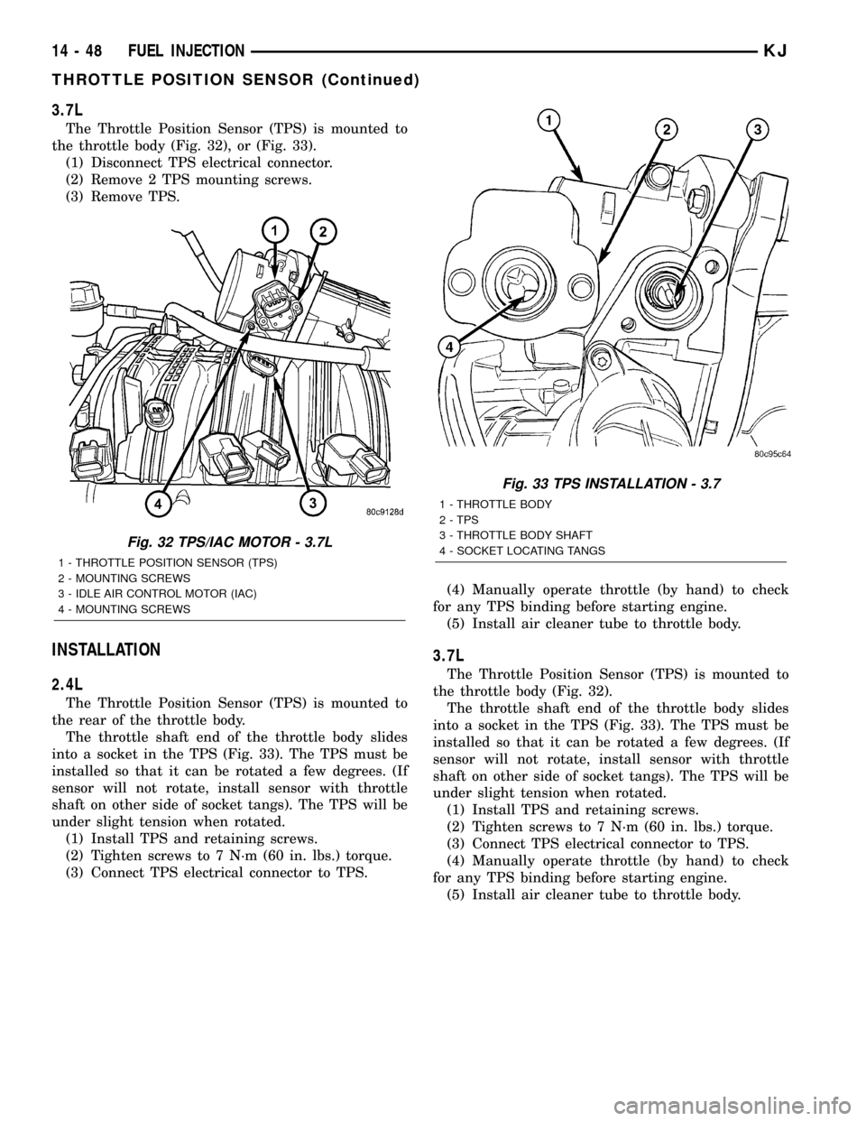
the throttle body (Fig. 32), or (Fig. 33).
(1) Disconnect TPS electrical connector.
(2) Remove 2 TPS mounting screws.
(3) Remove TPS.
INSTALLATION
2.4L
The Throttle Position Sensor (TPS) is mounted to
the rear of the throttle body.
The throttle shaft end of the throttle body slides
into a socket in the TPS (Fig. 33). The TPS must be
installed so that it can be rotated a few degrees. (If
sensor will not rotate, install sensor with throttle
shaft on other side of socket tangs). The TPS will be
under slight tension when rotated.
(1) Install TPS and retaining screws.
(2) Tighten screws to 7 N´m (60 in. lbs.) torque.
(3) Connect TPS electrical connector to TPS.(4) Manually operate throttle (by hand) to check
for any TPS binding before starting engine.
(5) Install air cleaner tube to throttle body.
3.7L
The Throttle Position Sensor (TPS) is mounted to
the throttle body (Fig. 32).
The throttle shaft end of the throttle body slides
into a socket in the TPS (Fig. 33). The TPS must be
installed so that it can be rotated a few degrees. (If
sensor will not rotate, install sensor with throttle
shaft on other side of socket tangs). The TPS will be
under slight tension when rotated.
(1) Install TPS and retaining screws.
(2) Tighten screws to 7 N´m (60 in. lbs.) torque.
(3) Connect TPS electrical connector to TPS.
(4) Manually operate throttle (by hand) to check
for any TPS binding before starting engine.
(5) Install air cleaner tube to throttle body.
Fig. 32 TPS/IAC MOTOR - 3.7L
1 - THROTTLE POSITION SENSOR (TPS)
2 - MOUNTING SCREWS
3 - IDLE AIR CONTROL MOTOR (IAC)
4 - MOUNTING SCREWS
Fig. 33 TPS INSTALLATION - 3.7
1 - THROTTLE BODY
2 - TPS
3 - THROTTLE BODY SHAFT
4 - SOCKET LOCATING TANGS
14 - 48 FUEL INJECTIONKJ
THROTTLE POSITION SENSOR (Continued)
Page 1440 of 1803
KEY-IN IGNITION SWITCH
DESCRIPTION
The key-in ignition switch is integral to the igni-
tion switch, which is mounted on the left side of the
steering column, opposite the ignition lock cylinder.
It closes a path to ground for the instrument cluster
chime warning circuitry when the ignition key is
inserted in the ignition lock cylinder and the driver
door jamb switch is closed (driver door is open). The
key-in ignition switch opens the ground path when
the key is removed from the ignition lock cylinder.
The key-in ignition switch cannot be repaired and,
if faulty or damaged, the entire ignition switch must
be replaced. (Refer to 19 - STEERING/COLUMN/IG-
NITION SWITCH - REMOVAL).
DIAGNOSIS AND TESTING - KEY-IN IGNITION
SWITCH
For circuit descriptions and diagrams, Refer to the
appropriate sections on the individual components.
WARNING: ON VEHICLES EQUIPPED WITH AIR-
BAGS, REFER TO ELECTRICAL - PASSIVE
RESTRAINT SYSTEMS BEFORE ATTEMPTING ANY
STEERING WHEEL, STEERING COLUMN, OR
INSTRUMENT PANEL COMPONENT DIAGNOSIS OR
SERVICE. FAILURE TO TAKE THE PROPER PRE-
CAUTIONS COULD RESULT IN ACCIDENTAL AIR-
BAG DEPLOYMENT AND POSSIBLE PERSONAL
INJURY.
(1) Disconnect and isolate the battery negative
cable. Remove the steering column shrouds. Unplug
the key-in ignition switch wire harness connector
from the ignition switch.
(2) Check for continuity between the key-in switch
sense circuit and the left front door jamb switch
sense circuit terminals of the key-in ignition switch.
There should be continuity with the key in the igni-
tion lock cylinder, and no continuity with the key
removed from the ignition lock cylinder. If OK, go to
Step 3. If not OK, replace the faulty ignition switch
assembly.
(3) Check for continuity between the left front door
jamb switch sense circuit cavity of the key-in ignition
switch wire harness connector and a good ground.
There should be continuity with the driver door open,
and no continuity with the driver door closed. If OK,
see the diagnosis for Instrument Cluster in this
group. If not OK, repair the circuit to the driver door
jamb switch as required.
LOCK CYLINDER
REMOVAL
The ignition key must be in the key cylinder for
cylinder removal. The key cylinder must be removed
first before removing ignition switch.
(1) If equipped with an automatic transmission,
place shifter in PARK position.
(2) Remove the lower shroud cover.
(3) Remove the remote keyless entry (R.K.E.) mod-
ule.
(4) Remove the halo ring around the lock cylinder.
(5) Rotate key to ON position.
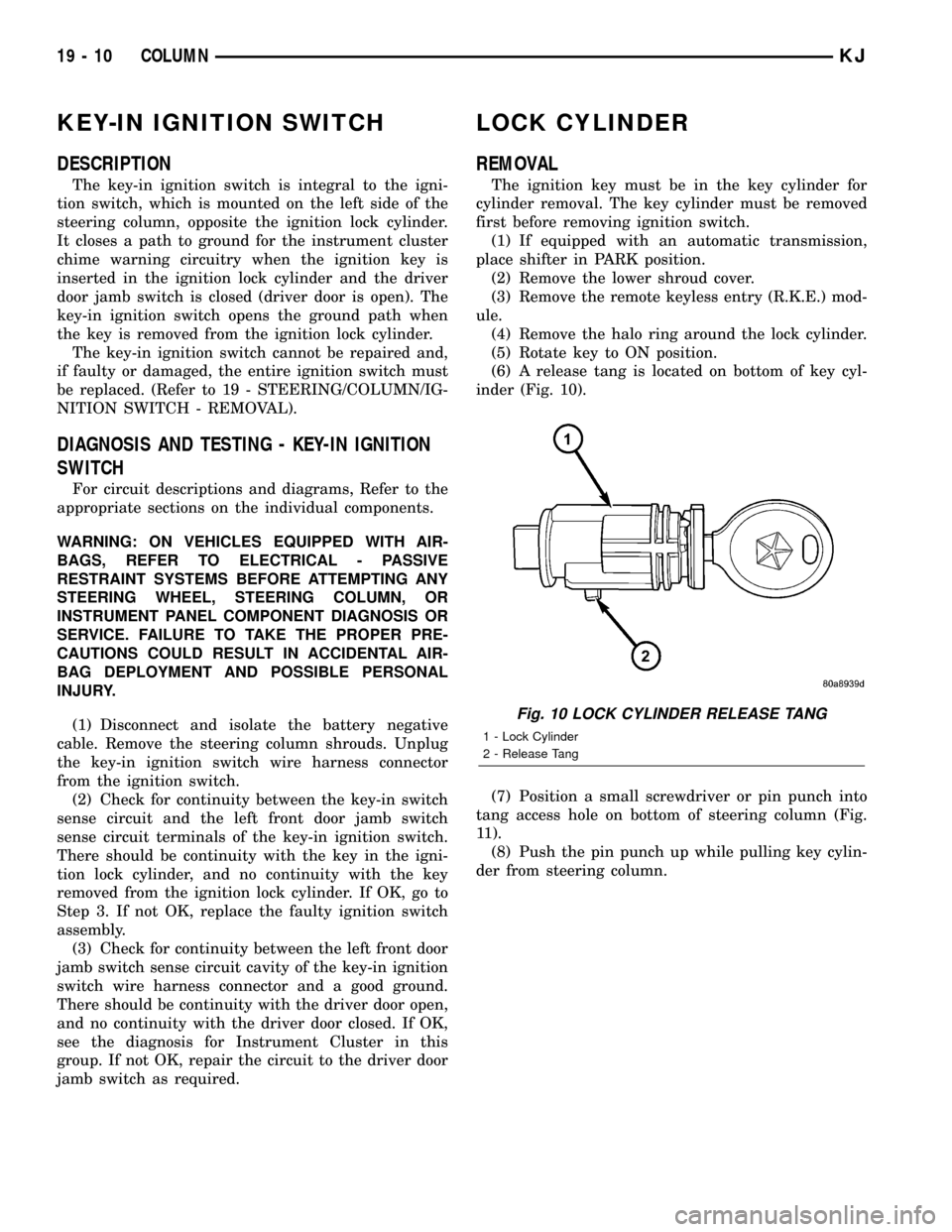
(6) A release tang is located on bottom of key cyl-
inder (Fig. 10).
(7) Position a small screwdriver or pin punch into
tang access hole on bottom of steering column (Fig.
11).
(8) Push the pin punch up while pulling key cylin-
der from steering column.
Fig. 10 LOCK CYLINDER RELEASE TANG
1 - Lock Cylinder
2 - Release Tang
19 - 10 COLUMNKJ
Page 1447 of 1803
PUMP
TABLE OF CONTENTS
page page
PUMP
DESCRIPTION.........................17
OPERATION...........................17
STANDARD PROCEDURE - POWER
STEERING PUMP - INITIAL OPERATION....18
REMOVAL
REMOVAL - 3.7L......................18
REMOVAL - 2.4L......................18
INSTALLATION
INSTALLATION - 3.7L..................19
INSTALLATION - 2.4L..................19
SPECIFICATIONS
TORQUE CHART......................19
SPECIAL TOOLS
POWER STEERING PUMP..............20
FLUID COOLER
DESCRIPTION.........................20
OPERATION...........................20
REMOVAL.............................20
INSTALLATION.........................20
HOSES
REMOVAL
REMOVAL - PRESSURE HOSE...........21
REMOVAL - RETURN HOSE (GEAR TO THE
COOLER)...........................21REMOVAL - RETURN HOSE (RESERVOIR
TO THE COOLER).....................21
INSTALLATION
INSTALLATION - PRESSURE HOSE.......21
INSTALLATION - RETURN HOSE (GEAR TO
THE COOLER)........................22
INSTALLATION - RETURN HOSE
(RESERVOIR TO THE COOLER)..........22
POWER STEERING PRESSURE SWITCH
DESCRIPTION.........................22
OPERATION...........................22
REMOVAL.............................22
INSTALLATION.........................22
PULLEY
REMOVAL.............................23
INSTALLATION.........................23
RESERVOIR
REMOVAL
REMOVAL - 3.7L......................24
REMOVAL - 2.4L......................24
INSTALLATION
INSTALLATION - 3.7L..................24
INSTALLATION - 2.4L..................24
PUMP
DESCRIPTION
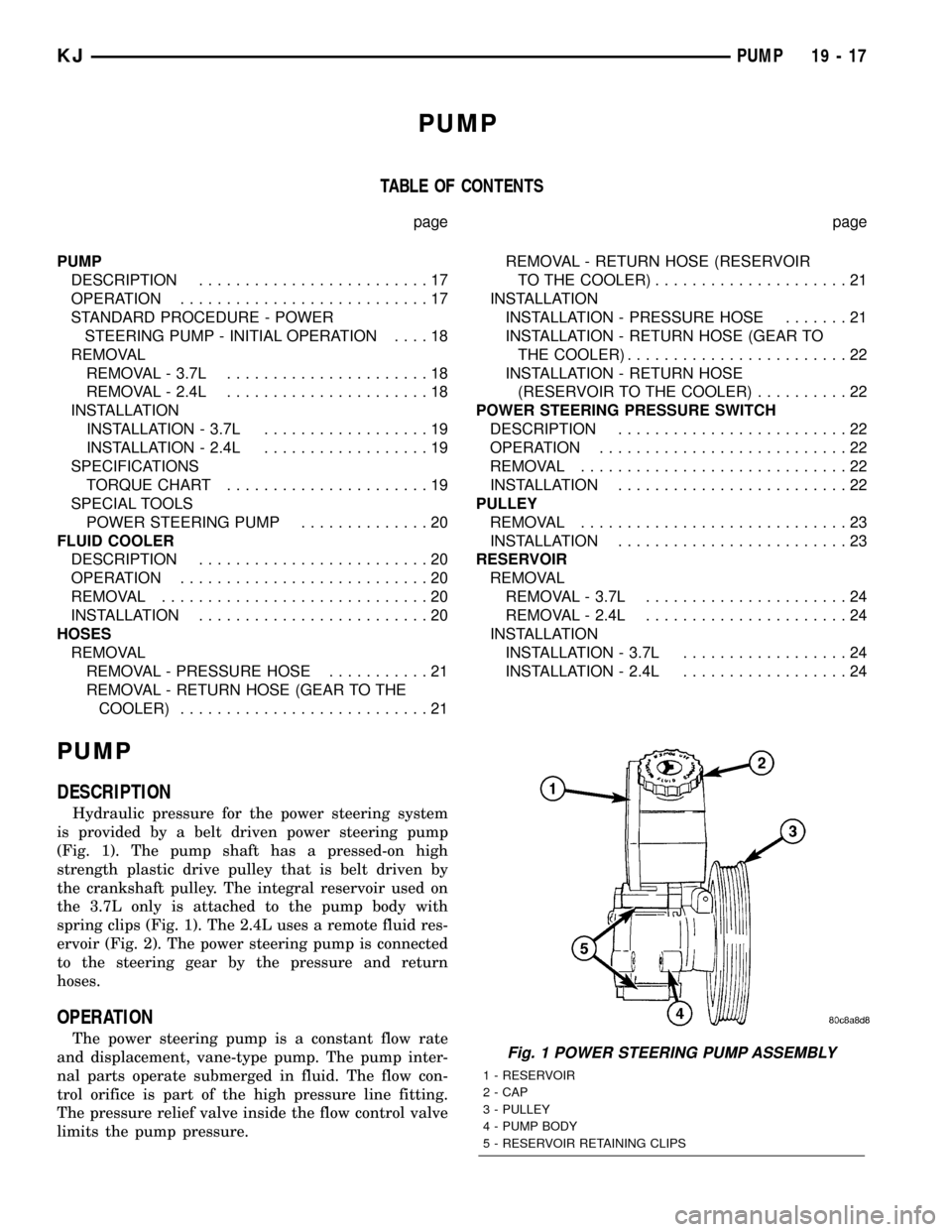
Hydraulic pressure for the power steering system
is provided by a belt driven power steering pump
(Fig. 1). The pump shaft has a pressed-on high
strength plastic drive pulley that is belt driven by
the crankshaft pulley. The integral reservoir used on
the 3.7L only is attached to the pump body with
spring clips (Fig. 1). The 2.4L uses a remote fluid res-
ervoir (Fig. 2). The power steering pump is connected
to the steering gear by the pressure and return
hoses.
OPERATION
The power steering pump is a constant flow rate
and displacement, vane-type pump. The pump inter-
nal parts operate submerged in fluid. The flow con-
trol orifice is part of the high pressure line fitting.
The pressure relief valve inside the flow control valve
limits the pump pressure.Fig. 1 POWER STEERING PUMP ASSEMBLY
1 - RESERVOIR
2 - CAP
3 - PULLEY
4 - PUMP BODY
5 - RESERVOIR RETAINING CLIPS
KJPUMP 19 - 17
Page 1456 of 1803
METHOD 1 (RELOCATE WHEEL ON HUB)
(1) Drive vehicle a short distance to eliminate tire
flat spotting from a parked position.
(2) Check wheel bearings and adjust if adjustable
or replace if necessary.
(3) Check the wheel mounting surface.
(4) Relocate wheel on the mounting, two studs
over from the original position.
(5) Tighten wheel nuts until all are properly
torqued, to eliminate brake distortion.
(6) Check radial runout. If still excessive, mark
tire sidewall, wheel, and stud at point of maximum
runout and proceed to Method 2.
METHOD 2 (RELOCATE TIRE ON WHEEL)
NOTE: Rotating the tire on wheel is particularly
effective when there is runout in both tire and
wheel.
(1) Remove tire from wheel and mount wheel on
service dynamic balance machine.
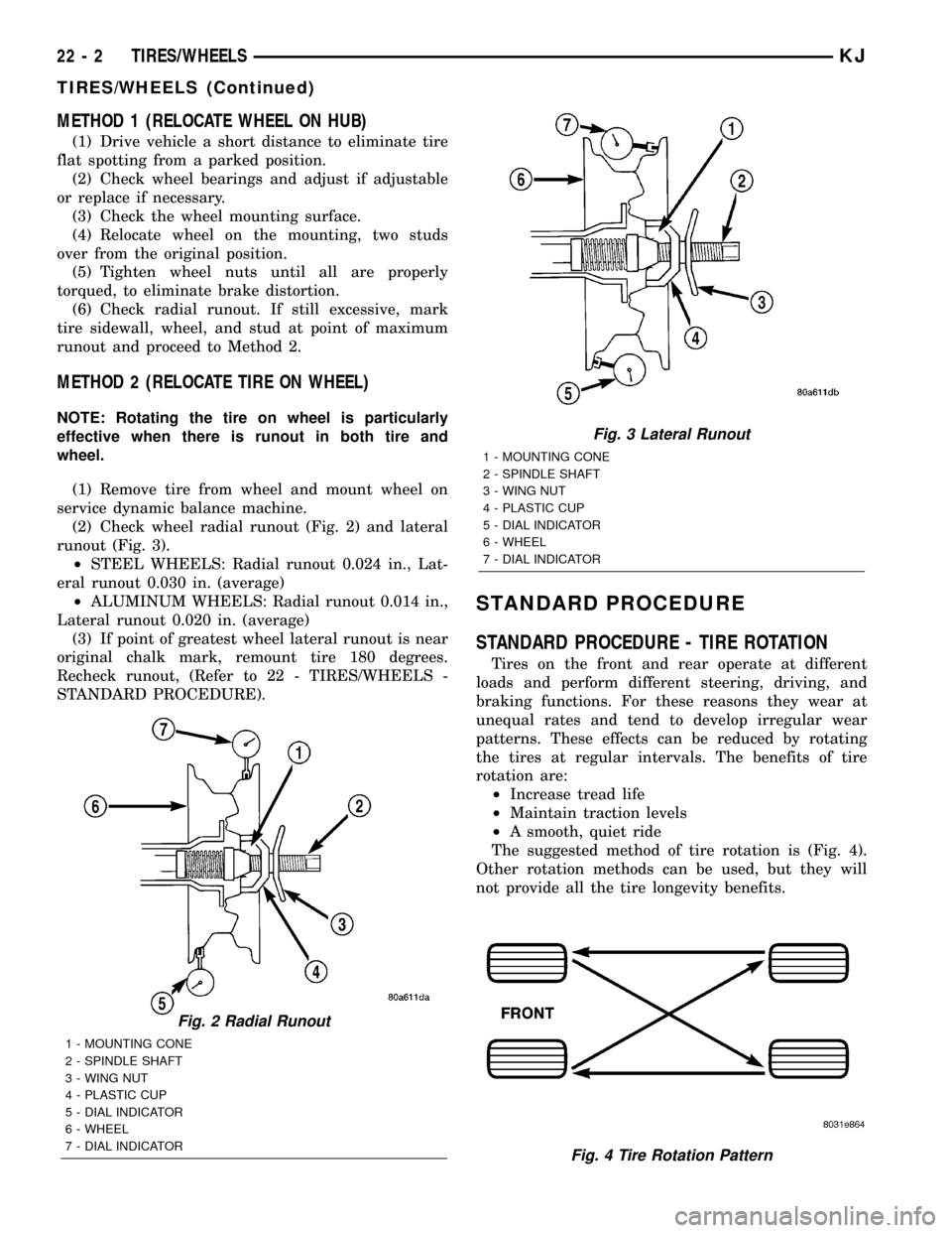
(2) Check wheel radial runout (Fig. 2) and lateral
runout (Fig. 3).
²STEEL WHEELS: Radial runout 0.024 in., Lat-
eral runout 0.030 in. (average)
²ALUMINUM WHEELS: Radial runout 0.014 in.,
Lateral runout 0.020 in. (average)
(3) If point of greatest wheel lateral runout is near
original chalk mark, remount tire 180 degrees.
Recheck runout, (Refer to 22 - TIRES/WHEELS -
STANDARD PROCEDURE).
STANDARD PROCEDURE
STANDARD PROCEDURE - TIRE ROTATION
Tires on the front and rear operate at different
loads and perform different steering, driving, and
braking functions. For these reasons they wear at
unequal rates and tend to develop irregular wear
patterns. These effects can be reduced by rotating
the tires at regular intervals. The benefits of tire
rotation are:
²Increase tread life
²Maintain traction levels
²A smooth, quiet ride
The suggested method of tire rotation is (Fig. 4).
Other rotation methods can be used, but they will
not provide all the tire longevity benefits.
Fig. 2 Radial Runout
1 - MOUNTING CONE
2 - SPINDLE SHAFT
3 - WING NUT
4 - PLASTIC CUP
5 - DIAL INDICATOR
6 - WHEEL
7 - DIAL INDICATOR
Fig. 3 Lateral Runout
1 - MOUNTING CONE
2 - SPINDLE SHAFT
3 - WING NUT
4 - PLASTIC CUP
5 - DIAL INDICATOR
6 - WHEEL
7 - DIAL INDICATOR
Fig. 4 Tire Rotation Pattern
22 - 2 TIRES/WHEELSKJ
TIRES/WHEELS (Continued)
Page 1457 of 1803
STANDARD PROCEDURE - MATCH MOUNTING
Tires and wheels are currently match mounted at
the factory. Match mounting is a technique used to
reduce runout in the wheel/tire assembly. This means
that the high spot of the tire is aligned with the low
spot on the wheel rim. The high spot on the tire is
marked with a paint mark or a bright colored adhe-
sive label on the outboard sidewall. The low spot on
the rim is identified with a label on the outside of the
rim and a dot on the inside of the rim. If the outside
label has been removed the tire will have to be
removed to locate the dot on the inside of the rim.
Before dismounting a tire from its wheel, a refer-
ence mark should be placed on the tire at the valve
stem location. This reference will ensure that it is
remounted in the original position on the wheel.
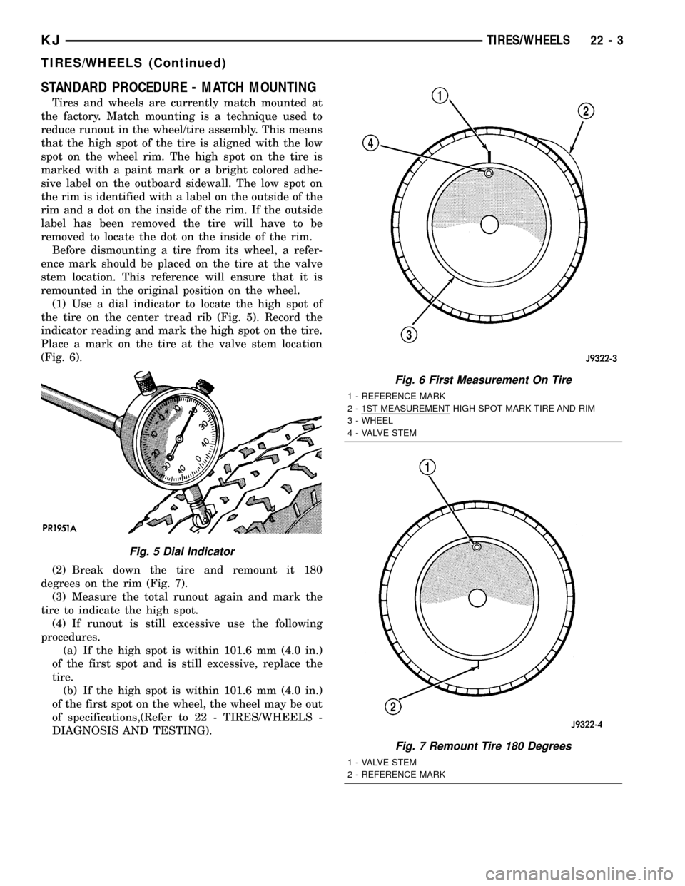
(1) Use a dial indicator to locate the high spot of
the tire on the center tread rib (Fig. 5). Record the
indicator reading and mark the high spot on the tire.
Place a mark on the tire at the valve stem location
(Fig. 6).
(2) Break down the tire and remount it 180
degrees on the rim (Fig. 7).
(3) Measure the total runout again and mark the
tire to indicate the high spot.
(4) If runout is still excessive use the following
procedures.
(a) If the high spot is within 101.6 mm (4.0 in.)
of the first spot and is still excessive, replace the
tire.
(b) If the high spot is within 101.6 mm (4.0 in.)
of the first spot on the wheel, the wheel may be out
of specifications,(Refer to 22 - TIRES/WHEELS -
DIAGNOSIS AND TESTING).
Fig. 5 Dial Indicator
Fig. 6 First Measurement On Tire
1 - REFERENCE MARK
2 - 1ST MEASUREMENT HIGH SPOT MARK TIRE AND RIM
3 - WHEEL
4 - VALVE STEM
Fig. 7 Remount Tire 180 Degrees
1 - VALVE STEM
2 - REFERENCE MARK
KJTIRES/WHEELS 22 - 3
TIRES/WHEELS (Continued)
Page 1458 of 1803
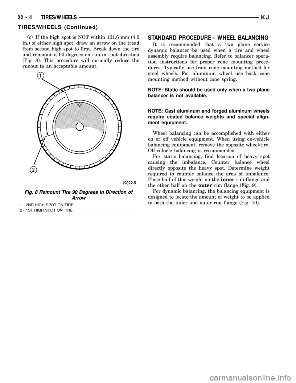
(c) If the high spot is NOT within 101.6 mm (4.0
in.) of either high spot, draw an arrow on the tread
from second high spot to first. Break down the tire
and remount it 90 degrees on rim in that direction
(Fig. 8). This procedure will normally reduce the
runout to an acceptable amount.STANDARD PROCEDURE - WHEEL BALANCING
It is recommended that a two plane service
dynamic balancer be used when a tire and wheel
assembly require balancing. Refer to balancer opera-
tion instructions for proper cone mounting proce-
dures. Typically use front cone mounting method for
steel wheels. For aluminum wheel use back cone
mounting method without cone spring.
NOTE: Static should be used only when a two plane
balancer is not available.
NOTE: Cast aluminum and forged aluminum wheels
require coated balance weights and special align-
ment equipment.
Wheel balancing can be accomplished with either
on or off vehicle equipment. When using on-vehicle
balancing equipment, remove the opposite wheel/tire.
Off-vehicle balancing is recommended.
For static balancing, find location of heavy spot
causing the imbalance. Counter balance wheel
directly opposite the heavy spot. Determine weight
required to counter balance the area of imbalance.
Place half of this weight on theinnerrim flange and
the other half on theouterrim flange (Fig. 9).
For dynamic balancing, the balancing equipment is
designed to locate the amount of weight to be applied
to both the inner and outer rim flange (Fig. 10).
Fig. 8 Remount Tire 90 Degrees In Direction of
Arrow
1 - 2ND HIGH SPOT ON TIRE
2 - 1ST HIGH SPOT ON TIRE
22 - 4 TIRES/WHEELSKJ
TIRES/WHEELS (Continued)
Page 1638 of 1803

WINDSHIELD
WARNING
WINDSHIELD SAFETY PRECAUTIONS
WARNING: DO NOT OPERATE THE VEHICLE
WITHIN 24 HOURS OF WINDSHIELD INSTALLATION.
IT TAKES AT LEAST 24 HOURS FOR URETHANE
ADHESIVE TO CURE. IF IT IS NOT CURED, THE
WINDSHIELD MAY NOT PERFORM PROPERLY IN
AN ACCIDENT.
²URETHANE ADHESIVES ARE APPLIED AS A
SYSTEM. USE GLASS CLEANER, GLASS PREP
SOLVENT, GLASS PRIMER, PVC (VINYL) PRIMER
AND PINCH WELD (FENCE) PRIMER PROVIDED BY
THE ADHESIVE MANUFACTURER. IF NOT, STRUC-
TURAL INTEGRITY COULD BE COMPROMISED.
²DAIMLERCHRYSLER DOES NOT RECOMMEND
GLASS ADHESIVE BY BRAND. TECHNICIANS
SHOULD REVIEW PRODUCT LABELS AND TECHNI-
CAL DATA SHEETS, AND USE ONLY ADHESIVES
THAT THEIR MANUFACTURES WARRANT WILL
RESTORE A VEHICLE TO THE REQUIREMENTS OF
FMVSS 212. TECHNICIANS SHOULD ALSO INSURE
THAT PRIMERS AND CLEANERS ARE COMPATIBLE
WITH THE PARTICULAR ADHESIVE USED.
²BE SURE TO REFER TO THE URETHANE MAN-
UFACTURER'S DIRECTIONS FOR CURING TIME
SPECIFICATIONS, AND DO NOT USE ADHESIVE
AFTER ITS EXPIRATION DATE.
²VAPORS THAT ARE EMITTED FROM THE URE-
THANE ADHESIVE OR PRIMER COULD CAUSE
PERSONAL INJURY. USE THEM IN A WELL-VENTI-
LATED AREA.
²SKIN CONTACT WITH URETHANE ADHESIVE
SHOULD BE AVOIDED. PERSONAL INJURY MAY
RESULT.
²ALWAYS WEAR EYE AND HAND PROTECTION
WHEN WORKING WITH GLASS.
CAUTION: Protect all painted and trimmed surfaces
from coming in contact with urethane or primers.
Be careful not to damage painted surfaces when
removing moldings or cutting urethane around
windshield.
REMOVAL
(1) Remove inside rear view mirror. (Refer to 23 -
BODY/INTERIOR/REAR VIEW MIRROR -
REMOVAL)
(2) Remove cowl cover. (Refer to 23 - BODY/EXTE-
RIOR/COWL GRILLE - REMOVAL)(3) Remove screws attaching windshield side mold-
ing to A-pillar.
(4) Remove upper windshield molding.
(5) Cut urethane bonding from around windshield
using a suitable sharp cold knife. A pneumatic cut-
ting device can be used if available.
(6) Separate windshield from vehicle.
INSTALLATION
WARNING: REVIEW ALL WARNINGS AND CAU-
TIONS IN THIS GROUP BEFORE PRECEDING WITH
INSTALLATION.
CAUTION: Open a window before installing wind-
shield. This will avoid pressurizing the passenger
compartment. If a door or swing gate flip-up glass
is slammed before urethane is cured, water leaks
can result.
The windshield fence should be cleaned of old ure-
thane bonding material. Support spacers should be
cleaned and properly installed on weld studs or
repair screws at bottom of windshield opening.
(1) Place replacement windshield into windshield
opening. Position glass in the center of the opening
against the support spacers. Mark the glass at the
support spacers with a grease pencil or masking tape
and ink pen to use as a reference for installation.
Remove replacement windshield from windshield
opening.
(2) Position the windshield inside up on a suitable
work surface with two padded, wood 10 cm by 10 cm
by 50 cm (4 in. by 4 in. by 20 in.) blocks, placed par-
allel 75 cm (2.5 ft.) apart.
(3) Clean inside of windshield with Mopar Glass
Cleaner and lint-free cloth.
(4) Apply clear glass primer 25 mm (1 in.) wide
around edge of windshield. Wipe with clean/dry lint-
free cloth.
(5) Apply black-out primer 15 mm (.75 in.) wide on
top and sides of windshield and 25 mm (1 in.) on bot-
tom of windshield. Allow at least three minutes dry-
ing time.
(6) Position windshield spacers on lower fence
above support spacers at the edge of the windshield
opening.
(7) Align the dot on the upper molding to the tick
mark in the center of the glass and install upper
molding onto windshield.
(8) Apply a 10 mm (0.4 in.) bead of urethane
around perimeter of windshield along the inside of
the moldings. Apply two beads along the bottom
edge.
KJSTATIONARY GLASS 23 - 173