2002 JEEP LIBERTY Ignition switch
[x] Cancel search: Ignition switchPage 1148 of 1803
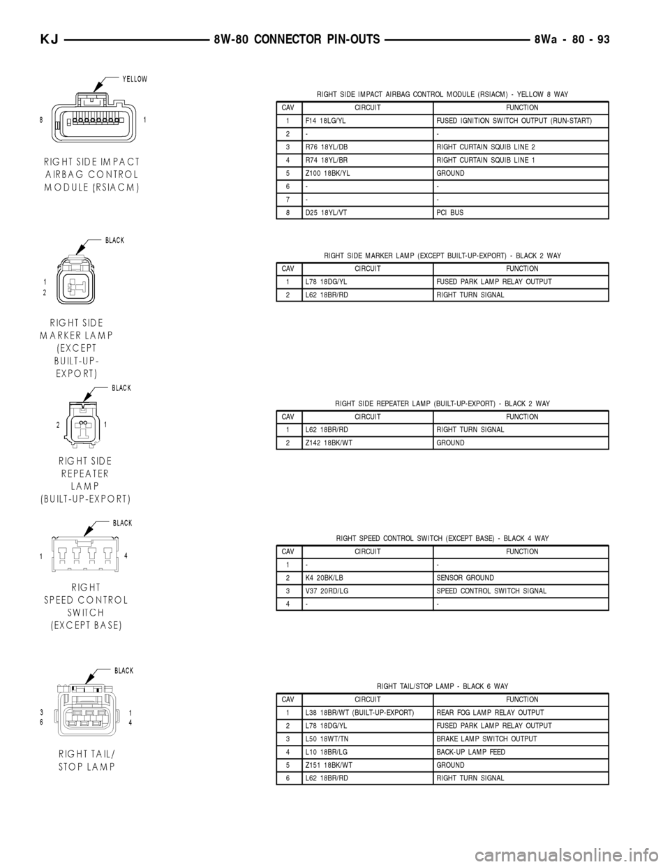
RIGHT SIDE IMPACT AIRBAG CONTROL MODULE (RSIACM) - YELLOW 8 WAY
CAV CIRCUIT FUNCTION
1 F14 18LG/YL FUSED IGNITION SWITCH OUTPUT (RUN-START)
2- -
3 R76 18YL/DB RIGHT CURTAIN SQUIB LINE 2
4 R74 18YL/BR RIGHT CURTAIN SQUIB LINE 1
5 Z100 18BK/YL GROUND
6- -
7- -
8 D25 18YL/VT PCI BUS
RIGHT SIDE MARKER LAMP (EXCEPT BUILT-UP-EXPORT) - BLACK 2 WAY
CAV CIRCUIT FUNCTION
1 L78 18DG/YL FUSED PARK LAMP RELAY OUTPUT
2 L62 18BR/RD RIGHT TURN SIGNAL
RIGHT SIDE REPEATER LAMP (BUILT-UP-EXPORT) - BLACK 2 WAY
CAV CIRCUIT FUNCTION
1 L62 18BR/RD RIGHT TURN SIGNAL
2 Z142 18BK/WT GROUND
RIGHT SPEED CONTROL SWITCH (EXCEPT BASE) - BLACK 4 WAY
CAV CIRCUIT FUNCTION
1- -
2 K4 20BK/LB SENSOR GROUND
3 V37 20RD/LG SPEED CONTROL SWITCH SIGNAL
4- -
RIGHT TAIL/STOP LAMP - BLACK 6 WAY
CAV CIRCUIT FUNCTION
1 L38 18BR/WT (BUILT-UP-EXPORT) REAR FOG LAMP RELAY OUTPUT
2 L78 18DG/YL FUSED PARK LAMP RELAY OUTPUT
3 L50 18WT/TN BRAKE LAMP SWITCH OUTPUT
4 L10 18BR/LG BACK-UP LAMP FEED
5 Z151 18BK/WT GROUND
6 L62 18BR/RD RIGHT TURN SIGNAL
KJ8W-80 CONNECTOR PIN-OUTS8Wa-80-93
Page 1149 of 1803
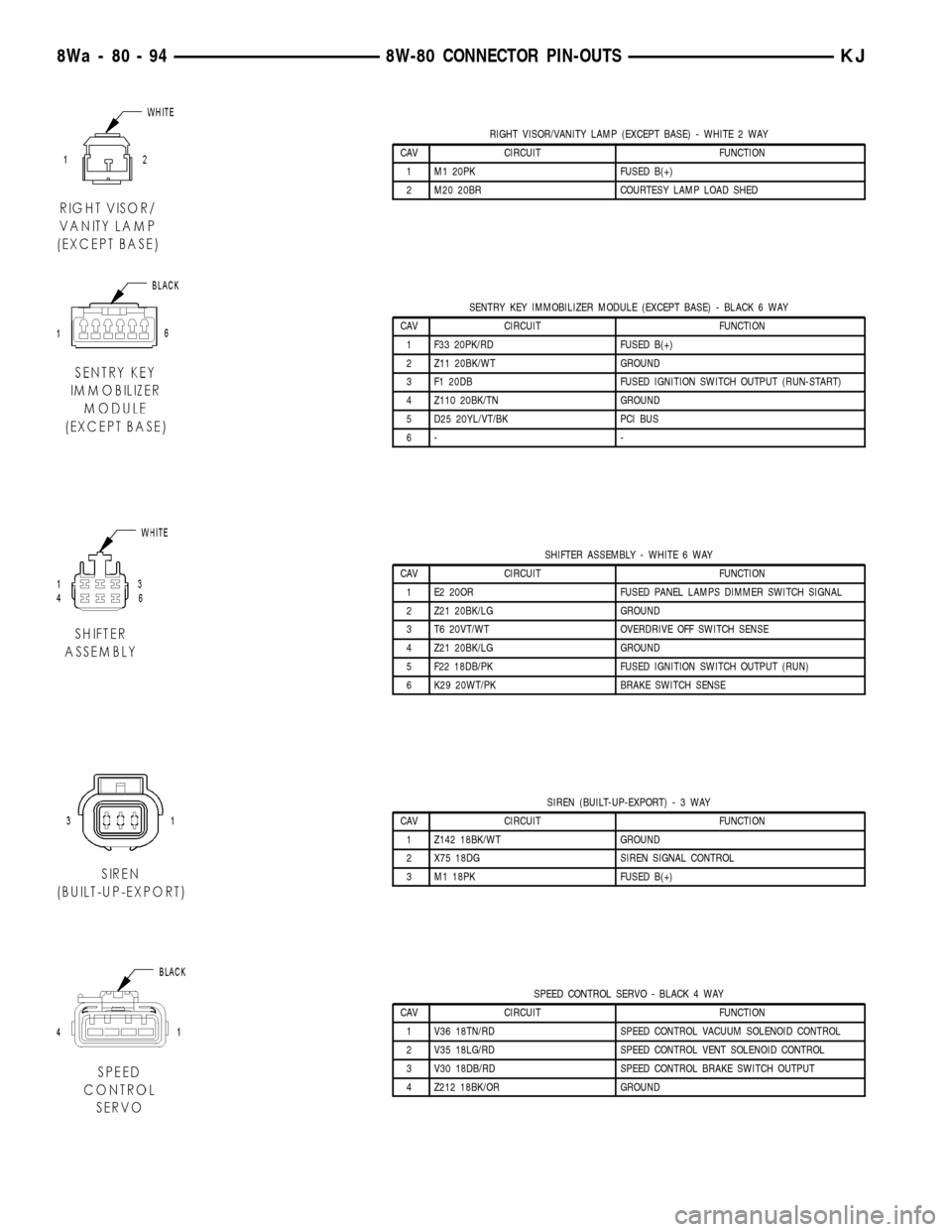
RIGHT VISOR/VANITY LAMP (EXCEPT BASE) - WHITE 2 WAY
CAV CIRCUIT FUNCTION
1 M1 20PK FUSED B(+)
2 M20 20BR COURTESY LAMP LOAD SHED
SENTRY KEY IMMOBILIZER MODULE (EXCEPT BASE) - BLACK 6 WAY
CAV CIRCUIT FUNCTION
1 F33 20PK/RD FUSED B(+)
2 Z11 20BK/WT GROUND
3 F1 20DB FUSED IGNITION SWITCH OUTPUT (RUN-START)
4 Z110 20BK/TN GROUND
5 D25 20YL/VT/BK PCI BUS
6- -
SHIFTER ASSEMBLY - WHITE 6 WAY
CAV CIRCUIT FUNCTION
1 E2 20OR FUSED PANEL LAMPS DIMMER SWITCH SIGNAL
2 Z21 20BK/LG GROUND
3 T6 20VT/WT OVERDRIVE OFF SWITCH SENSE
4 Z21 20BK/LG GROUND
5 F22 18DB/PK FUSED IGNITION SWITCH OUTPUT (RUN)
6 K29 20WT/PK BRAKE SWITCH SENSE
SIREN (BUILT-UP-EXPORT)-3WAY
CAV CIRCUIT FUNCTION
1 Z142 18BK/WT GROUND
2 X75 18DG SIREN SIGNAL CONTROL
3 M1 18PK FUSED B(+)
SPEED CONTROL SERVO - BLACK 4 WAY
CAV CIRCUIT FUNCTION
1 V36 18TN/RD SPEED CONTROL VACUUM SOLENOID CONTROL
2 V35 18LG/RD SPEED CONTROL VENT SOLENOID CONTROL
3 V30 18DB/RD SPEED CONTROL BRAKE SWITCH OUTPUT
4 Z212 18BK/OR GROUND
8Wa - 80 - 94 8W-80 CONNECTOR PIN-OUTSKJ
Page 1150 of 1803
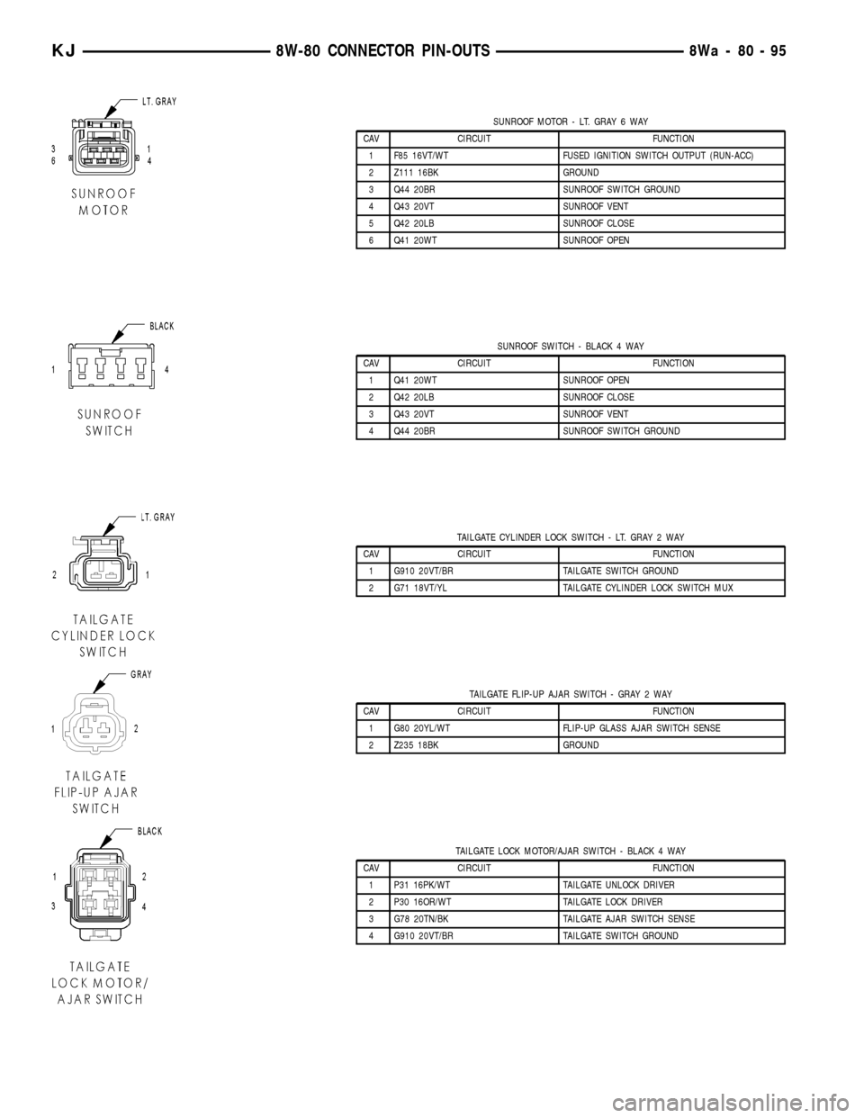
SUNROOF MOTOR - LT. GRAY 6 WAY
CAV CIRCUIT FUNCTION
1 F85 16VT/WT FUSED IGNITION SWITCH OUTPUT (RUN-ACC)
2 Z111 16BK GROUND
3 Q44 20BR SUNROOF SWITCH GROUND
4 Q43 20VT SUNROOF VENT
5 Q42 20LB SUNROOF CLOSE
6 Q41 20WT SUNROOF OPEN
SUNROOF SWITCH - BLACK 4 WAY
CAV CIRCUIT FUNCTION
1 Q41 20WT SUNROOF OPEN
2 Q42 20LB SUNROOF CLOSE
3 Q43 20VT SUNROOF VENT
4 Q44 20BR SUNROOF SWITCH GROUND
TAILGATE CYLINDER LOCK SWITCH - LT. GRAY 2 WAY
CAV CIRCUIT FUNCTION
1 G910 20VT/BR TAILGATE SWITCH GROUND
2 G71 18VT/YL TAILGATE CYLINDER LOCK SWITCH MUX
TAILGATE FLIP-UP AJAR SWITCH - GRAY 2 WAY
CAV CIRCUIT FUNCTION
1 G80 20YL/WT FLIP-UP GLASS AJAR SWITCH SENSE
2 Z235 18BK GROUND
TAILGATE LOCK MOTOR/AJAR SWITCH - BLACK 4 WAY
CAV CIRCUIT FUNCTION
1 P31 16PK/WT TAILGATE UNLOCK DRIVER
2 P30 16OR/WT TAILGATE LOCK DRIVER
3 G78 20TN/BK TAILGATE AJAR SWITCH SENSE
4 G910 20VT/BR TAILGATE SWITCH GROUND
KJ8W-80 CONNECTOR PIN-OUTS8Wa-80-95
Page 1152 of 1803
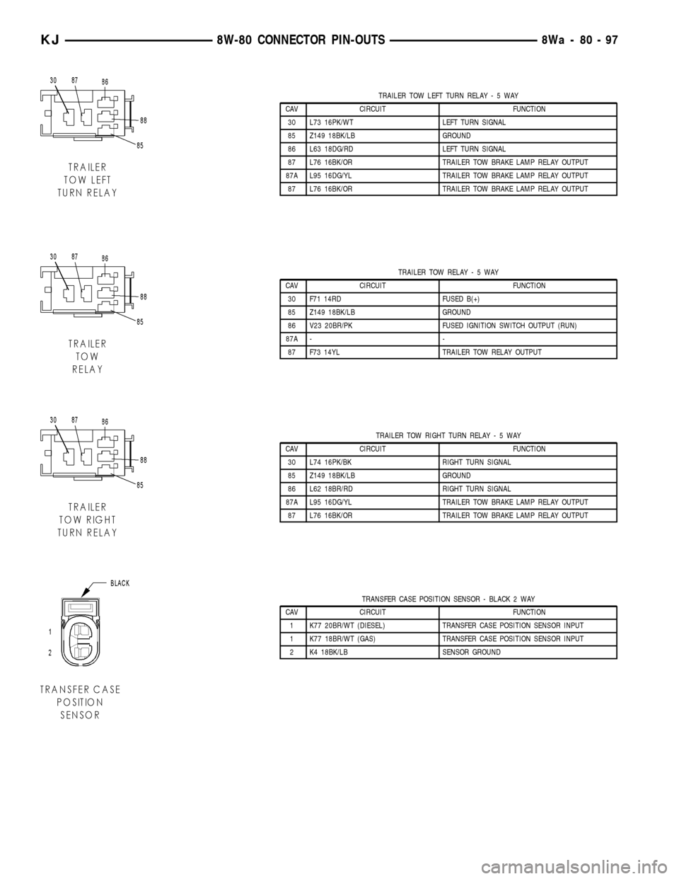
TRAILER TOW LEFT TURN RELAY-5WAY
CAV CIRCUIT FUNCTION
30 L73 16PK/WT LEFT TURN SIGNAL
85 Z149 18BK/LB GROUND
86 L63 18DG/RD LEFT TURN SIGNAL
87 L76 16BK/OR TRAILER TOW BRAKE LAMP RELAY OUTPUT
87A L95 16DG/YL TRAILER TOW BRAKE LAMP RELAY OUTPUT
87 L76 16BK/OR TRAILER TOW BRAKE LAMP RELAY OUTPUT
TRAILER TOW RELAY-5WAY
CAV CIRCUIT FUNCTION
30 F71 14RD FUSED B(+)
85 Z149 18BK/LB GROUND
86 V23 20BR/PK FUSED IGNITION SWITCH OUTPUT (RUN)
87A - -
87 F73 14YL TRAILER TOW RELAY OUTPUT
TRAILER TOW RIGHT TURN RELAY-5WAY
CAV CIRCUIT FUNCTION
30 L74 16PK/BK RIGHT TURN SIGNAL
85 Z149 18BK/LB GROUND
86 L62 18BR/RD RIGHT TURN SIGNAL
87A L95 16DG/YL TRAILER TOW BRAKE LAMP RELAY OUTPUT
87 L76 16BK/OR TRAILER TOW BRAKE LAMP RELAY OUTPUT
TRANSFER CASE POSITION SENSOR - BLACK 2 WAY
CAV CIRCUIT FUNCTION
1 K77 20BR/WT (DIESEL) TRANSFER CASE POSITION SENSOR INPUT
1 K77 18BR/WT (GAS) TRANSFER CASE POSITION SENSOR INPUT
2 K4 18BK/LB SENSOR GROUND
KJ8W-80 CONNECTOR PIN-OUTS8Wa-80-97
Page 1153 of 1803
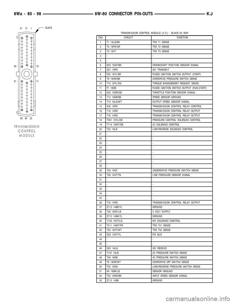
TRANSMISSION CONTROL MODULE (3.7L) - BLACK 60 WAY
CAV CIRCUIT FUNCTION
1 T1 18LG/BK TRS T1 SENSE
2 T4 18PK/OR TRS T2 SENSE
3 T3 18VT TRS T3 SENSE
4- -
5- -
6 K24 18GY/BK CRANKSHAFT POSITION SENSOR SIGNAL
7 D21 18PK SCI TRANSMIT
8 F45 18YL/BR FUSED IGNITION SWITCH OUTPUT (START)
9 T9 18OR/BK OVERDRIVE PRESSURE SWITCH SENSE
10 T10 18YL/DG TORQUE MANAGEMENT REQUEST SENSE
11 F1 18DB FUSED IGNITION SWITCH OUTPUT (RUN-START)
12 K22 18OR/DB THROTTLE POSITION SENSOR SIGNAL
13 T13 18DB/BK SPEED SENSOR GROUND
14 T14 18LG/WT OUTPUT SPEED SENSOR SIGNAL
15 K30 18PK TRANSMISSION CONTROL RELAY CONTROL
16 T16 14RD TRANSMISSION CONTROL RELAY OUTPUT
17 T16 14RD TRANSMISSION CONTROL RELAY OUTPUT
18 T591 18YL/DB PRESSURE CONTROL SOLENOID CONTROL
19 T119 18WT/DB 2C SOLENOID CONTROL
20 T20 18LB LOW/REVERSE SOLENOID CONTROL
21 - -
22 - -
23 - -
24 - -
25 - -
26 - -
27 - -
28 - -
29 T29 18GY UNDERDRIVE PRESSURE SWITCH SENSE
30 T38 18VT/TN LINE PRESSURE SENSOR SIGNAL
31 - -
32 - -
33 - -
34 - -
35 - -
36 T16 14RD TRANSMISSION CONTROL RELAY OUTPUT
37 Z113 14BK/YL GROUND
38 T39 18GY/LB 5 VOLT SUPPLY
39 Z113 14BK/YL GROUND
40 T140 18VT/LG MS SOLENOID CONTROL
41 T411 18WT/PK TRS T41 SENSE
42 T42 18VT/WT TRS T42 SENSE
43 D25 18VT/YL PCI BUS
44 - -
45 - -
46 D20 18LG SCI RECEIVE
47 T147 18LB 2C PRESSURE SWITCH SENSE
48 T48 18DB 4C PRESSURE SWITCH SENSE
49 T6 18OR/WT OVERDRIVE OFF SWITCH SENSE
50 T50 18DG LOW/REVERSE PRESSURE SWITCH SENSE
51 K4 18BK/LB SENSOR GROUND
52 T52 18RD/BK INPUT SPEED SENSOR SIGNAL
53 Z112 14BK GROUND
8Wa - 80 - 98 8W-80 CONNECTOR PIN-OUTSKJ
Page 1154 of 1803
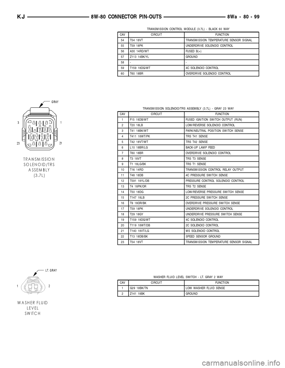
TRANSMISSION CONTROL MODULE (3.7L) - BLACK 60 WAY
CAV CIRCUIT FUNCTION
54 T54 18VT TRANSMISSION TEMPERATURE SENSOR SIGNAL
55 T59 18PK UNDERDRIVE SOLENOID CONTROL
56 A30 14RD/WT FUSED B(+)
57 Z113 14BK/YL GROUND
58 - -
59 T159 18DG/WT 4C SOLENOID CONTROL
60 T60 18BR OVERDRIVE SOLENOID CONTROL
TRANSMISSION SOLENOID/TRS ASSEMBLY (3.7L) - GRAY 23 WAY
CAV CIRCUIT FUNCTION
1 F15 18DB/WT FUSED IGNITION SWITCH OUTPUT (RUN)
2 T20 18LB LOW/REVERSE SOLENOID CONTROL
3 T41 18BK/WT PARK/NEUTRAL POSITION SWITCH SENSE
4 T411 18WT/PK TRS T41 SENSE
5 T42 18VT/WT TRS T42 SENSE
6 L10 18BR/LG BACK-UP LAMP FEED
7 T60 18BR OVERDRIVE SOLENOID CONTROL
8 T3 18VT TRS T3 SENSE
9 T1 18LG/BK TRS T1 SENSE
10 T16 14RD TRANSMISSION CONTROL RELAY OUTPUT
11 T48 18DB 4C PRESSURE SWITCH SENSE
12 T591 18YL/DB PRESSURE CONTROL SOLENOID CONTROL
13 T4 18PK/OR TRS T2 SENSE
14 T50 18DG LOW/REVERSE PRESSURE SWITCH SENSE
15 T147 18LB 2C PRESSURE SWITCH SENSE
16 T9 18OR/BK OVERDRIVE PRESSURE SWITCH SENSE
17 T59 18PK UNDERDRIVE SOLENOID CONTROL
18 T29 18GY UNDERDRIVE PRESSURE SWITCH SENSE
19 T159 18DG/WT 4C SOLENOID CONTROL
20 T119 18WT/DB 2C SOLENOID CONTROL
21 T140 18VT/LG MS SOLENOID CONTROL
22 T13 18DB/BK SPEED SENSOR GROUND
23 T54 18VT TRANSMISSION TEMPERATURE SENSOR SIGNAL
WASHER FLUID LEVEL SWITCH - LT. GRAY 2 WAY
CAV CIRCUIT FUNCTION
1 G29 18BK/TN LOW WASHER FLUID SENSE
2 Z141 18BK GROUND
KJ8W-80 CONNECTOR PIN-OUTS8Wa-80-99
Page 1160 of 1803
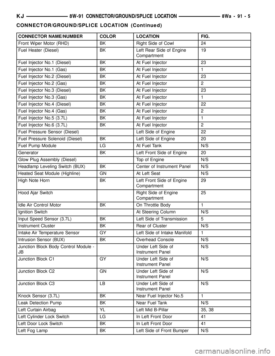
CONNECTOR NAME/NUMBER COLOR LOCATION FIG.
Front Wiper Motor (RHD) BK Right Side of Cowl 24
Fuel Heater (Diesel) BK Left Rear Side of Engine
Compartment19
Fuel Injector No.1 (Diesel) BK At Fuel Injector 23
Fuel Injector No.1 (Gas) BK At Fuel Injector 1
Fuel Injector No.2 (Diesel) BK At Fuel Injector 23
Fuel Injector No.2 (Gas) BK At Fuel Injector 2
Fuel Injector No.3 (Diesel) BK At Fuel Injector 23
Fuel Injector No.3 (Gas) BK At Fuel Injector 1
Fuel Injector No.4 (Diesel) BK At Fuel Injector 22
Fuel Injector No.4 (Gas) BK At Fuel Injector 2
Fuel Injector No.5 (3.7L) BK At Fuel Injector 1
Fuel Injector No.6 (3.7L) BK At Fuel Injector 2
Fuel Pressure Sensor (Diesel) Left Side of Engine 22
Fuel Pressure Solenoid (Diesel) BK Left Side of Engine 20
Fuel Pump Module LG At Fuel Tank N/S
Generator BK Left Front Side of Engine 20
Glow Plug Assembly (Diesel) Top of Engine N/S
Headlamp Leveling Switch (BUX) BK Center of Instrument Panel N/S
Heated Seat Module (Highline) GN At Left Seat N/S
High Note Horn BK Left Front Side of Engine
Compartment29
Hood Ajar Switch Right Side of Engine
Compartment25
Idle Air Control Motor BK On Throttle Body 1
Ignition Switch At Steering Column N/S
Input Speed Sensor (3.7L) BK Left Side of Transmission 5
Instrument Cluster BK Rear of Cluster N/S
Intake Air Temperature Sensor GY Left Side of Intake Manifold 1
Intrusion Sensor (BUX) BK Overhead Console N/S
Junction Block Body Control Module -
JBUnder Left Side of
Instrument PanelN/S
Junction Block C1 GY Under Left Side of
Instrument PanelN/S
Junction Block C2 GN Under Left Side of
Instrument PanelN/S
Junction Block C3 LB Under Left Side of
Instrument PanelN/S
Knock Sensor (3.7L) BK Near Fuel Injector No.5 1
Leak Detection Pump BK Near Fuel Tank N/S
Left Curtain Airbag YL Left Mid B-Pillar 35, 38
Left Cylinder Lock Switch LG In Left Front Door 41
Left Door Lock Switch BK In Left Front Door 41
Left Fog Lamp BK Left Side of Front Bumper N/S
KJ8W-91 CONNECTOR/GROUND/SPLICE LOCATION8Wa-91-5
CONNECTOR/GROUND/SPLICE LOCATION (Continued)
Page 1415 of 1803
FUEL INJECTOR
DESCRIPTION
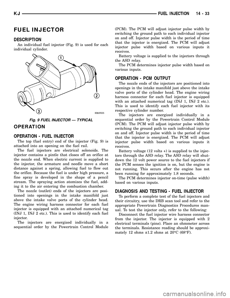
An individual fuel injector (Fig. 9) is used for each
individual cylinder.
OPERATION
OPERATION - FUEL INJECTOR
The top (fuel entry) end of the injector (Fig. 9) is
attached into an opening on the fuel rail.
The fuel injectors are electrical solenoids. The
injector contains a pintle that closes off an orifice at
the nozzle end. When electric current is supplied to
the injector, the armature and needle move a short
distance against a spring, allowing fuel to flow out
the orifice. Because the fuel is under high pressure, a
fine spray is developed in the shape of a pencil
stream. The spraying action atomizes the fuel, add-
ing it to the air entering the combustion chamber.
The nozzle (outlet) ends of the injectors are posi-
tioned into openings in the intake manifold just
above the intake valve ports of the cylinder head.
The engine wiring harness connector for each fuel
injector is equipped with an attached numerical tag
(INJ 1, INJ 2 etc.). This is used to identify each fuel
injector.
The injectors are energized individually in a
sequential order by the Powertrain Control Module(PCM). The PCM will adjust injector pulse width by
switching the ground path to each individual injector
on and off. Injector pulse width is the period of time
that the injector is energized. The PCM will adjust
injector pulse width based on various inputs it
receives.
Battery voltage is supplied to the injectors through
the ASD relay.
The PCM determines injector pulse width based on
various inputs.
OPERATION - PCM OUTPUT
The nozzle ends of the injectors are positioned into
openings in the intake manifold just above the intake
valve ports of the cylinder head. The engine wiring
harness connector for each fuel injector is equipped
with an attached numerical tag (INJ 1, INJ 2 etc.).
This is used to identify each fuel injector with its
respective cylinder number.
The injectors are energized individually in a
sequential order by the Powertrain Control Module
(PCM). The PCM will adjust injector pulse width by
switching the ground path to each individual injector
on and off. Injector pulse width is the period of time
that the injector is energized. The PCM will adjust
injector pulse width based on various inputs it
receives.
Battery voltage (12 volts +) is supplied to the injec-
tors through the ASD relay. The ASD relay will shut-
down the 12 volt power source to the fuel injectors if
the PCM senses the ignition is on, but the engine is
not running. This occurs after the engine has not
been running for approximately 1.8 seconds.
The PCM determines injector on-time (pulse width)
based on various inputs.
DIAGNOSIS AND TESTING - FUEL INJECTOR
To perform a complete test of the fuel injectors and
their circuitry, use the DRB scan tool and refer to the
appropriate Powertrain Diagnostics Procedures man-
ual. To test the injector only, refer to the following:
Disconnect the fuel injector wire harness connector
from the injector. The injector is equipped with 2
electrical terminals (pins). Place an ohmmeter across
the terminals. Resistance reading should be approxi-
mately 12 ohms 1.2 ohms at 20ÉC (68ÉF).
Fig. 9 FUEL INJECTOR Ð TYPICAL
KJFUEL INJECTION 14 - 33