2002 JEEP LIBERTY control panel
[x] Cancel search: control panelPage 1163 of 1803
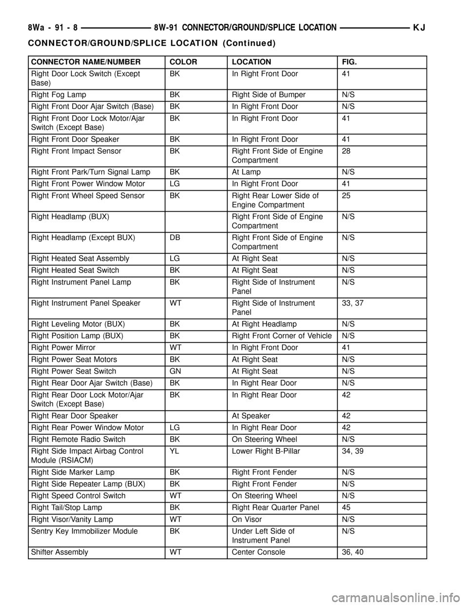
CONNECTOR NAME/NUMBER COLOR LOCATION FIG.
Right Door Lock Switch (Except
Base)BK In Right Front Door 41
Right Fog Lamp BK Right Side of Bumper N/S
Right Front Door Ajar Switch (Base) BK In Right Front Door N/S
Right Front Door Lock Motor/Ajar
Switch (Except Base)BK In Right Front Door 41
Right Front Door Speaker BK In Right Front Door 41
Right Front Impact Sensor BK Right Front Side of Engine
Compartment28
Right Front Park/Turn Signal Lamp BK At Lamp N/S
Right Front Power Window Motor LG In Right Front Door 41
Right Front Wheel Speed Sensor BK Right Rear Lower Side of
Engine Compartment25
Right Headlamp (BUX) Right Front Side of Engine
CompartmentN/S
Right Headlamp (Except BUX) DB Right Front Side of Engine
CompartmentN/S
Right Heated Seat Assembly LG At Right Seat N/S
Right Heated Seat Switch BK At Right Seat N/S
Right Instrument Panel Lamp BK Right Side of Instrument
PanelN/S
Right Instrument Panel Speaker WT Right Side of Instrument
Panel33, 37
Right Leveling Motor (BUX) BK At Right Headlamp N/S
Right Position Lamp (BUX) BK Right Front Corner of Vehicle N/S
Right Power Mirror WT In Right Front Door 41
Right Power Seat Motors BK At Right Seat N/S
Right Power Seat Switch GN At Right Seat N/S
Right Rear Door Ajar Switch (Base) BK In Right Rear Door N/S
Right Rear Door Lock Motor/Ajar
Switch (Except Base)BK In Right Rear Door 42
Right Rear Door Speaker At Speaker 42
Right Rear Power Window Motor LG In Right Rear Door 42
Right Remote Radio Switch BK On Steering Wheel N/S
Right Side Impact Airbag Control
Module (RSIACM)YL Lower Right B-Pillar 34, 39
Right Side Marker Lamp BK Right Front Fender N/S
Right Side Repeater Lamp (BUX) BK Right Front Fender N/S
Right Speed Control Switch WT On Steering Wheel N/S
Right Tail/Stop Lamp BK Right Rear Quarter Panel 45
Right Visor/Vanity Lamp WT On Visor N/S
Sentry Key Immobilizer Module BK Under Left Side of
Instrument PanelN/S
Shifter Assembly WT Center Console 36, 40
8Wa - 91 - 8 8W-91 CONNECTOR/GROUND/SPLICE LOCATIONKJ
CONNECTOR/GROUND/SPLICE LOCATION (Continued)
Page 1164 of 1803
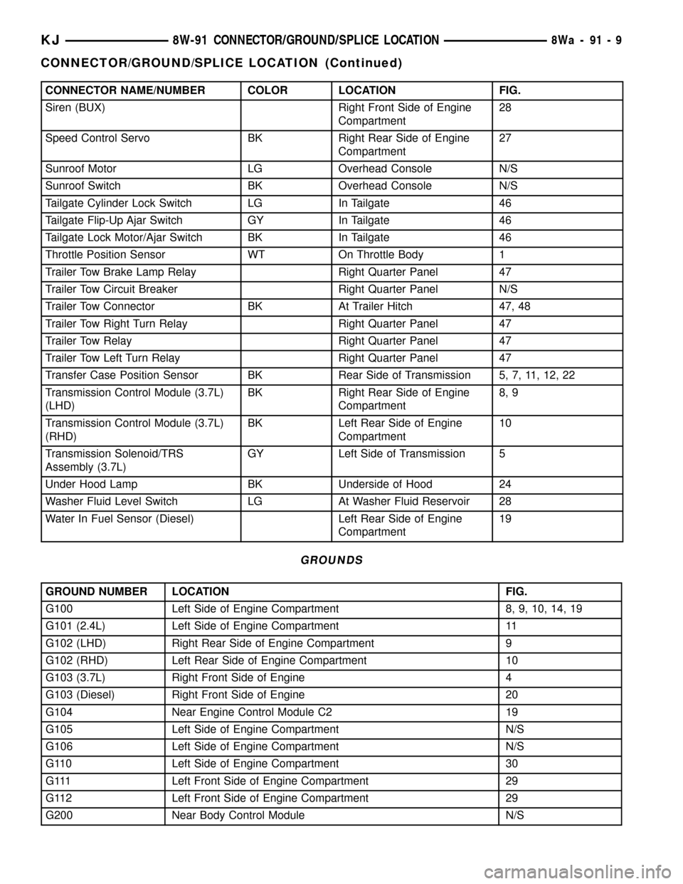
CONNECTOR NAME/NUMBER COLOR LOCATION FIG.
Siren (BUX) Right Front Side of Engine
Compartment28
Speed Control Servo BK Right Rear Side of Engine
Compartment27
Sunroof Motor LG Overhead Console N/S
Sunroof Switch BK Overhead Console N/S
Tailgate Cylinder Lock Switch LG In Tailgate 46
Tailgate Flip-Up Ajar Switch GY In Tailgate 46
Tailgate Lock Motor/Ajar Switch BK In Tailgate 46
Throttle Position Sensor WT On Throttle Body 1
Trailer Tow Brake Lamp Relay Right Quarter Panel 47
Trailer Tow Circuit Breaker Right Quarter Panel N/S
Trailer Tow Connector BK At Trailer Hitch 47, 48
Trailer Tow Right Turn Relay Right Quarter Panel 47
Trailer Tow Relay Right Quarter Panel 47
Trailer Tow Left Turn Relay Right Quarter Panel 47
Transfer Case Position Sensor BK Rear Side of Transmission 5, 7, 11, 12, 22
Transmission Control Module (3.7L)
(LHD)BK Right Rear Side of Engine
Compartment8, 9
Transmission Control Module (3.7L)
(RHD)BK Left Rear Side of Engine
Compartment10
Transmission Solenoid/TRS
Assembly (3.7L)GY Left Side of Transmission 5
Under Hood Lamp BK Underside of Hood 24
Washer Fluid Level Switch LG At Washer Fluid Reservoir 28
Water In Fuel Sensor (Diesel) Left Rear Side of Engine
Compartment19
GROUNDS
GROUND NUMBER LOCATION FIG.
G100 Left Side of Engine Compartment 8, 9, 10, 14, 19
G101 (2.4L) Left Side of Engine Compartment 11
G102 (LHD) Right Rear Side of Engine Compartment 9
G102 (RHD) Left Rear Side of Engine Compartment 10
G103 (3.7L) Right Front Side of Engine 4
G103 (Diesel) Right Front Side of Engine 20
G104 Near Engine Control Module C2 19
G105 Left Side of Engine Compartment N/S
G106 Left Side of Engine Compartment N/S
G110 Left Side of Engine Compartment 30
G111 Left Front Side of Engine Compartment 29
G112 Left Front Side of Engine Compartment 29
G200 Near Body Control Module N/S
KJ8W-91 CONNECTOR/GROUND/SPLICE LOCATION8Wa-91-9
CONNECTOR/GROUND/SPLICE LOCATION (Continued)
Page 1165 of 1803
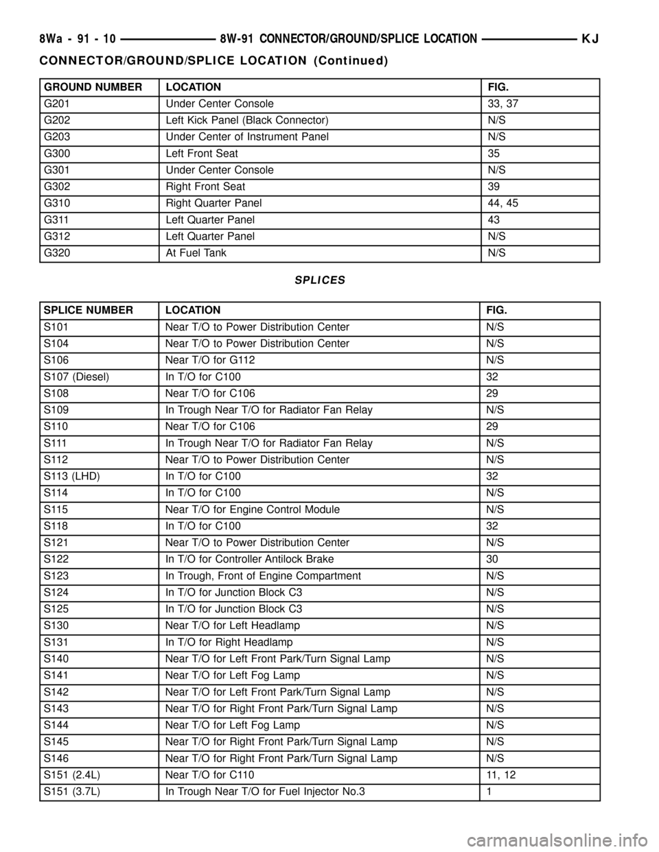
GROUND NUMBER LOCATION FIG.
G201 Under Center Console 33, 37
G202 Left Kick Panel (Black Connector) N/S
G203 Under Center of Instrument Panel N/S
G300 Left Front Seat 35
G301 Under Center Console N/S
G302 Right Front Seat 39
G310 Right Quarter Panel 44, 45
G311 Left Quarter Panel 43
G312 Left Quarter Panel N/S
G320 At Fuel Tank N/S
SPLICES
SPLICE NUMBER LOCATION FIG.
S101 Near T/O to Power Distribution Center N/S
S104 Near T/O to Power Distribution Center N/S
S106 Near T/O for G112 N/S
S107 (Diesel) In T/O for C100 32
S108 Near T/O for C106 29
S109 In Trough Near T/O for Radiator Fan Relay N/S
S110 Near T/O for C106 29
S111 In Trough Near T/O for Radiator Fan Relay N/S
S112 Near T/O to Power Distribution Center N/S
S113 (LHD) In T/O for C100 32
S114 In T/O for C100 N/S
S115 Near T/O for Engine Control Module N/S
S118 In T/O for C100 32
S121 Near T/O to Power Distribution Center N/S
S122 In T/O for Controller Antilock Brake 30
S123 In Trough, Front of Engine Compartment N/S
S124 In T/O for Junction Block C3 N/S
S125 In T/O for Junction Block C3 N/S
S130 Near T/O for Left Headlamp N/S
S131 In T/O for Right Headlamp N/S
S140 Near T/O for Left Front Park/Turn Signal Lamp N/S
S141 Near T/O for Left Fog Lamp N/S
S142 Near T/O for Left Front Park/Turn Signal Lamp N/S
S143 Near T/O for Right Front Park/Turn Signal Lamp N/S
S144 Near T/O for Left Fog Lamp N/S
S145 Near T/O for Right Front Park/Turn Signal Lamp N/S
S146 Near T/O for Right Front Park/Turn Signal Lamp N/S
S151 (2.4L) Near T/O for C110 11, 12
S151 (3.7L) In Trough Near T/O for Fuel Injector No.3 1
8Wa - 91 - 10 8W-91 CONNECTOR/GROUND/SPLICE LOCATIONKJ
CONNECTOR/GROUND/SPLICE LOCATION (Continued)
Page 1166 of 1803
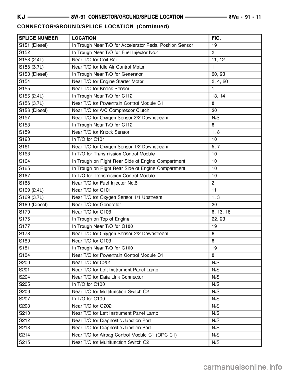
SPLICE NUMBER LOCATION FIG.
S151 (Diesel) In Trough Near T/O for Accelerator Pedal Position Sensor 19
S152 In Trough Near T/O for Fuel Injector No.4 2
S153 (2.4L) Near T/O for Coil Rail 11, 12
S153 (3.7L) Near T/O for Idle Air Control Motor 1
S153 (Diesel) In Trough Near T/O for Generator 20, 23
S154 Near T/O for Engine Starter Motor 2, 4, 20
S155 Near T/O for Knock Sensor 1
S156 (2.4L) In Trough Near T/O for C112 13, 14
S156 (3.7L) Near T/O for Powertrain Control Module C1 8
S156 (Diesel) Near T/O for A/C Compressor Clutch 20
S157 Near T/O for Oxygen Sensor 2/2 Downstream N/S
S158 In Trough Near T/O for C112 8
S159 Near T/O for Knock Sensor 1, 8
S160 In T/O for C104 10
S161 Near T/O for Oxygen Sensor 1/2 Downstream 5, 7
S163 In T/O for Transmission Control Module 10
S164 In Trough on Right Rear Side of Engine Compartment 10
S165 In Trough on Right Rear Side of Engine Compartment 10
S167 In T/O for Transmission Control Module 10
S168 Near T/O for Fuel Injector No.6 2
S169 (2.4L) Near T/O for C101 11
S169 (3.7L) Near T/O for Oxygen Sensor 1/1 Upstream 1, 3
S169 (Diesel) Near T/O for Generator 20
S170 Near T/O for C103 8, 13, 16
S175 In Trough on Top of Engine 22, 23
S177 In Trough Near T/O for G100 19
S178 Near T/O for Oxygen Sensor 2/2 Downstream 6
S180 Near T/O for C103 8
S181 In Trough Near T/O for G100 19
S184 Near T/O for Powertrain Control Module C1 8
S200 Near T/O for C201 N/S
S201 Near T/O for Left Instrument Panel Lamp N/S
S204 Near T/O for Data Link Connector N/S
S205 In T/O for C100 N/S
S206 Near T/O for Multifunction Switch C2 N/S
S207 In T/O for C100 N/S
S208 Near T/O for G202 N/S
S210 Near T/O for Left Instrument Panel Lamp N/S
S212 Near T/O for Diagnostic Junction Port N/S
S213 Near T/O for Diagnostic Junction Port N/S
S214 Near T/O for Airbag Control Module C1 (ORC C1) N/S
S215 Near T/O for Multifunction Switch C2 N/S
KJ8W-91 CONNECTOR/GROUND/SPLICE LOCATION8Wa-91-11
CONNECTOR/GROUND/SPLICE LOCATION (Continued)
Page 1167 of 1803
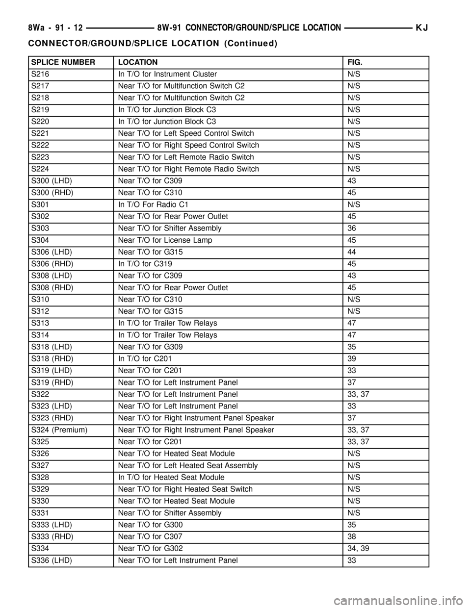
SPLICE NUMBER LOCATION FIG.
S216 In T/O for Instrument Cluster N/S
S217 Near T/O for Multifunction Switch C2 N/S
S218 Near T/O for Multifunction Switch C2 N/S
S219 In T/O for Junction Block C3 N/S
S220 In T/O for Junction Block C3 N/S
S221 Near T/O for Left Speed Control Switch N/S
S222 Near T/O for Right Speed Control Switch N/S
S223 Near T/O for Left Remote Radio Switch N/S
S224 Near T/O for Right Remote Radio Switch N/S
S300 (LHD) Near T/O for C309 43
S300 (RHD) Near T/O for C310 45
S301 In T/O For Radio C1 N/S
S302 Near T/O for Rear Power Outlet 45
S303 Near T/O for Shifter Assembly 36
S304 Near T/O for License Lamp 45
S306 (LHD) Near T/O for G315 44
S306 (RHD) In T/O for C319 45
S308 (LHD) Near T/O for C309 43
S308 (RHD) Near T/O for Rear Power Outlet 45
S310 Near T/O for C310 N/S
S312 Near T/O for G315 N/S
S313 In T/O for Trailer Tow Relays 47
S314 In T/O for Trailer Tow Relays 47
S318 (LHD) Near T/O for G309 35
S318 (RHD) In T/O for C201 39
S319 (LHD) Near T/O for C201 33
S319 (RHD) Near T/O for Left Instrument Panel 37
S322 Near T/O for Left Instrument Panel 33, 37
S323 (LHD) Near T/O for Left Instrument Panel 33
S323 (RHD) Near T/O for Right Instrument Panel Speaker 37
S324 (Premium) Near T/O for Right Instrument Panel Speaker 33, 37
S325 Near T/O for C201 33, 37
S326 Near T/O for Heated Seat Module N/S
S327 Near T/O for Left Heated Seat Assembly N/S
S328 In T/O for Heated Seat Module N/S
S329 Near T/O for Right Heated Seat Switch N/S
S330 Near T/O for Heated Seat Module N/S
S331 Near T/O for Shifter Assembly N/S
S333 (LHD) Near T/O for G300 35
S333 (RHD) Near T/O for C307 38
S334 Near T/O for G302 34, 39
S336 (LHD) Near T/O for Left Instrument Panel 33
8Wa - 91 - 12 8W-91 CONNECTOR/GROUND/SPLICE LOCATIONKJ
CONNECTOR/GROUND/SPLICE LOCATION (Continued)
Page 1391 of 1803

FUEL LEVEL SENDING UNIT /
SENSOR
DESCRIPTION
The fuel gauge sending unit (fuel level sensor) is
attached to the side of the fuel pump module. The
sending unit consists of a float, an arm, and a vari-
able resistor track (card).
OPERATION
The fuel pump module has 4 different circuits
(wires). Two of these circuits are used for the fuel
gauge sending unit for fuel gauge operation, and for
certain OBD II emission requirements. The other 2
wires are used for electric fuel pump operation.
For Fuel Gauge Operation:A constant current
source of approximately 32 milliamps is supplied to
the resistor track on the fuel gauge sending unit.
This is fed directly from the Powertrain Control Mod-
ule (PCM).NOTE: For diagnostic purposes, this
12V power source can only be verified with the
circuit opened (fuel pump module electrical
connector unplugged). With the connectors
plugged, output voltages will vary from about
0.6 volts at FULL, to about 8.6 volts at EMPTY
(about 8.6 volts at EMPTY for Jeep models, and
about 7.0 volts at EMPTY for Dodge Truck mod-
els).The resistor track is used to vary the voltage
(resistance) depending on fuel tank float level. As
fuel level increases, the float and arm move up,
which decreases voltage. As fuel level decreases, the
float and arm move down, which increases voltage.
The varied voltage signal is returned back to the
PCM through the sensor return circuit.
Both of the electrical circuits between the fuel
gauge sending unit and the PCM are hard-wired (not
multi-plexed). After the voltage signal is sent from
the resistor track, and back to the PCM, the PCM
will interpret the resistance (voltage) data and send
a message across the multi-plex bus circuits to the
instrument panel cluster. Here it is translated into
the appropriate fuel gauge level reading. Refer to
Instrument Panel for additional information.
For OBD II Emission Monitor Requirements:
The PCM will monitor the voltage output sent from
the resistor track on the sending unit to indicate fuel
level. The purpose of this feature is to prevent the
OBD II system from recording/setting false misfire
and fuel system monitor diagnostic trouble codes.
The feature is activated if the fuel level in the tank
is less than approximately 15 percent of its rated
capacity. If equipped with a Leak Detection Pump
(EVAP system monitor), this feature will also be acti-
vated if the fuel level in the tank is more than
approximately 85 percent of its rated capacity.
DIAGNOSIS AND TESTING - FUEL LEVEL
SENDING UNIT
The fuel level sending unit contains a variable
resistor (track). As the float moves up or down, elec-
trical resistance will change. Refer to Instrument
Panel and Gauges for Fuel Gauge testing. To test the
gauge sending unit only, it must be removed from
vehicle. The unit is a separate part of the lower fuel
pump module section. Refer to Fuel Pump Module
Removal/Installation for procedures (remove only the
upper section of the fuel pump module). Measure the
resistance across the sending unit terminals. With
float in up position, resistance should be 20 ohms (+/-
5%). With float in down position, resistance should be
270 ohms (+/- 5%).
REMOVAL
The fuel level sending unit (fuel level sensor) and
float assembly is located on the side of the lower sec-
tion of the fuel pump module. The lower section of
the fuel pump module is located within the fuel tank.
(1) Remove lower section of fuel pump module
from fuel tank. Refer to Fuel Pump Module Removal/
Installation.
(2) To remove sending unit from pump module, lift
on plastic locking tab (Fig. 8) while sliding sending
unit upwards.
(3) Disconnect 4±wire electrical connector (Fig. 9)
from bottom of upper section of fuel pump module.
Separate necessary sending unit wiring.
Fig. 8 FUEL LEVEL SENDING UNIT
1 - LIFT TAB HERE FOR REMOVAL
2 - FUEL LEVEL SENDING UNIT
3 - LOWER SECTION OF PUMP MODULE
KJFUEL DELIVERY 14 - 9
Page 1427 of 1803
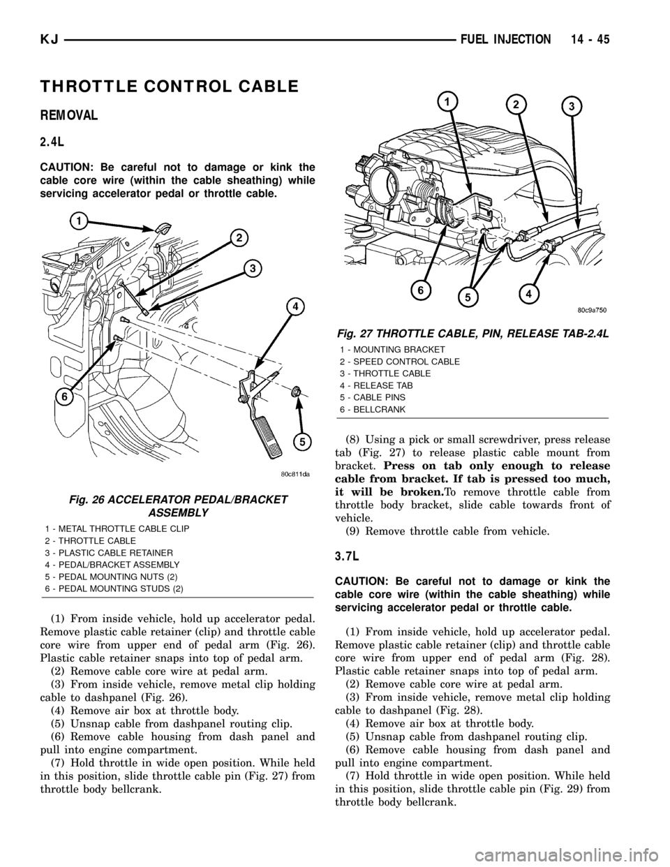
THROTTLE CONTROL CABLE
REMOVAL
2.4L
CAUTION: Be careful not to damage or kink the
cable core wire (within the cable sheathing) while
servicing accelerator pedal or throttle cable.
(1) From inside vehicle, hold up accelerator pedal.
Remove plastic cable retainer (clip) and throttle cable
core wire from upper end of pedal arm (Fig. 26).
Plastic cable retainer snaps into top of pedal arm.
(2) Remove cable core wire at pedal arm.
(3) From inside vehicle, remove metal clip holding
cable to dashpanel (Fig. 26).
(4) Remove air box at throttle body.
(5) Unsnap cable from dashpanel routing clip.
(6) Remove cable housing from dash panel and
pull into engine compartment.
(7) Hold throttle in wide open position. While held
in this position, slide throttle cable pin (Fig. 27) from
throttle body bellcrank.(8) Using a pick or small screwdriver, press release
tab (Fig. 27) to release plastic cable mount from
bracket.Press on tab only enough to release
cable from bracket. If tab is pressed too much,
it will be broken.To remove throttle cable from
throttle body bracket, slide cable towards front of
vehicle.
(9) Remove throttle cable from vehicle.
3.7L
CAUTION: Be careful not to damage or kink the
cable core wire (within the cable sheathing) while
servicing accelerator pedal or throttle cable.
(1) From inside vehicle, hold up accelerator pedal.
Remove plastic cable retainer (clip) and throttle cable
core wire from upper end of pedal arm (Fig. 28).
Plastic cable retainer snaps into top of pedal arm.
(2) Remove cable core wire at pedal arm.
(3) From inside vehicle, remove metal clip holding
cable to dashpanel (Fig. 28).
(4) Remove air box at throttle body.
(5) Unsnap cable from dashpanel routing clip.
(6) Remove cable housing from dash panel and
pull into engine compartment.
(7) Hold throttle in wide open position. While held
in this position, slide throttle cable pin (Fig. 29) from
throttle body bellcrank.
Fig. 26 ACCELERATOR PEDAL/BRACKET
ASSEMBLY
1 - METAL THROTTLE CABLE CLIP
2 - THROTTLE CABLE
3 - PLASTIC CABLE RETAINER
4 - PEDAL/BRACKET ASSEMBLY
5 - PEDAL MOUNTING NUTS (2)
6 - PEDAL MOUNTING STUDS (2)
Fig. 27 THROTTLE CABLE, PIN, RELEASE TAB-2.4L
1 - MOUNTING BRACKET
2 - SPEED CONTROL CABLE
3 - THROTTLE CABLE
4 - RELEASE TAB
5 - CABLE PINS
6 - BELLCRANK
KJFUEL INJECTION 14 - 45
Page 1428 of 1803
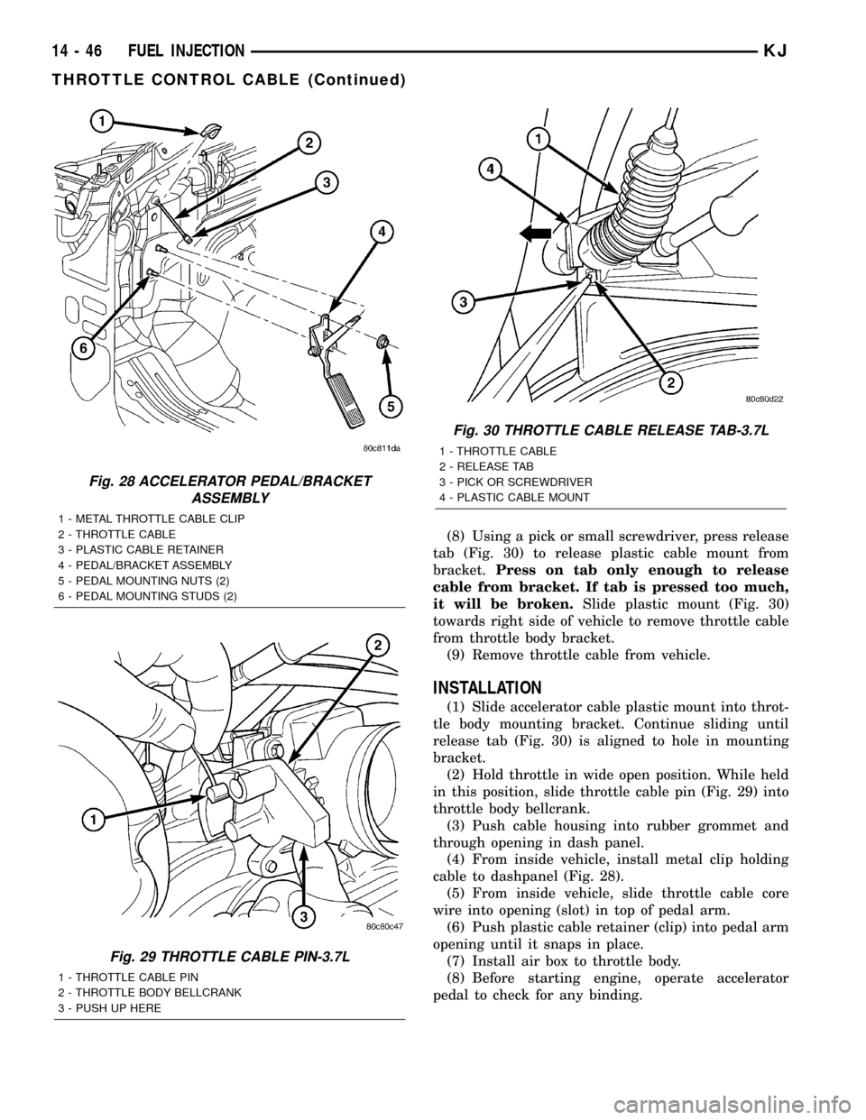
(8) Using a pick or small screwdriver, press release
tab (Fig. 30) to release plastic cable mount from
bracket.Press on tab only enough to release
cable from bracket. If tab is pressed too much,
it will be broken.Slide plastic mount (Fig. 30)
towards right side of vehicle to remove throttle cable
from throttle body bracket.
(9) Remove throttle cable from vehicle.
INSTALLATION
(1) Slide accelerator cable plastic mount into throt-
tle body mounting bracket. Continue sliding until
release tab (Fig. 30) is aligned to hole in mounting
bracket.
(2) Hold throttle in wide open position. While held
in this position, slide throttle cable pin (Fig. 29) into
throttle body bellcrank.
(3) Push cable housing into rubber grommet and
through opening in dash panel.
(4) From inside vehicle, install metal clip holding
cable to dashpanel (Fig. 28).
(5) From inside vehicle, slide throttle cable core
wire into opening (slot) in top of pedal arm.
(6) Push plastic cable retainer (clip) into pedal arm
opening until it snaps in place.
(7) Install air box to throttle body.
(8) Before starting engine, operate accelerator
pedal to check for any binding.
Fig. 28 ACCELERATOR PEDAL/BRACKET
ASSEMBLY
1 - METAL THROTTLE CABLE CLIP
2 - THROTTLE CABLE
3 - PLASTIC CABLE RETAINER
4 - PEDAL/BRACKET ASSEMBLY
5 - PEDAL MOUNTING NUTS (2)
6 - PEDAL MOUNTING STUDS (2)
Fig. 29 THROTTLE CABLE PIN-3.7L
1 - THROTTLE CABLE PIN
2 - THROTTLE BODY BELLCRANK
3 - PUSH UP HERE
Fig. 30 THROTTLE CABLE RELEASE TAB-3.7L
1 - THROTTLE CABLE
2 - RELEASE TAB
3 - PICK OR SCREWDRIVER
4 - PLASTIC CABLE MOUNT
14 - 46 FUEL INJECTIONKJ
THROTTLE CONTROL CABLE (Continued)