2002 JEEP LIBERTY fuel
[x] Cancel search: fuelPage 1461 of 1803
DESCRIPTION - REPLACEMENT TIRES
The original equipment tires provide a proper bal-
ance of many characteristics such as:
²Ride
²Noise
²Handling
²Durability
²Tread life
²Traction
²Rolling resistance
²Speed capability
It is recommended that tires equivalent to the orig-
inal equipment tires be used when replacement is
needed.
Failure to use equivalent replacement tires may
adversely affect the safety and handling of the vehi-
cle.
The use of oversize tires may cause interference
with vehicle components. Under extremes of suspen-
sion and steering travel, interference with vehicle
components may cause tire damage.
WARNING: FAILURE TO EQUIP THE VEHICLE WITH
TIRES HAVING ADEQUATE SPEED CAPABILITY
CAN RESULT IN SUDDEN TIRE FAILURE.
DIAGNOSIS AND TESTING
DIAGNOSIS AND TESTING - TIRE INFLATION
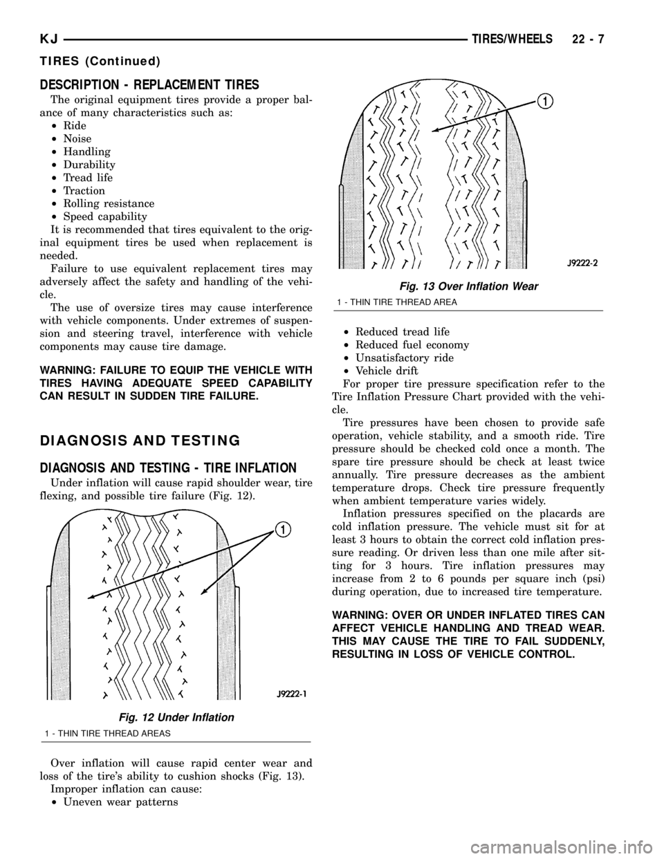
Under inflation will cause rapid shoulder wear, tire
flexing, and possible tire failure (Fig. 12).
Over inflation will cause rapid center wear and
loss of the tire's ability to cushion shocks (Fig. 13).
Improper inflation can cause:
²Uneven wear patterns²Reduced tread life
²Reduced fuel economy
²Unsatisfactory ride
²Vehicle drift
For proper tire pressure specification refer to the
Tire Inflation Pressure Chart provided with the vehi-
cle.
Tire pressures have been chosen to provide safe
operation, vehicle stability, and a smooth ride. Tire
pressure should be checked cold once a month. The
spare tire pressure should be check at least twice
annually. Tire pressure decreases as the ambient
temperature drops. Check tire pressure frequently
when ambient temperature varies widely.
Inflation pressures specified on the placards are
cold inflation pressure. The vehicle must sit for at
least 3 hours to obtain the correct cold inflation pres-
sure reading. Or driven less than one mile after sit-
ting for 3 hours. Tire inflation pressures may
increase from 2 to 6 pounds per square inch (psi)
during operation, due to increased tire temperature.
WARNING: OVER OR UNDER INFLATED TIRES CAN
AFFECT VEHICLE HANDLING AND TREAD WEAR.
THIS MAY CAUSE THE TIRE TO FAIL SUDDENLY,
RESULTING IN LOSS OF VEHICLE CONTROL.
Fig. 12 Under Inflation
1 - THIN TIRE THREAD AREAS
Fig. 13 Over Inflation Wear
1 - THIN TIRE THREAD AREA
KJTIRES/WHEELS 22 - 7
TIRES (Continued)
Page 1475 of 1803
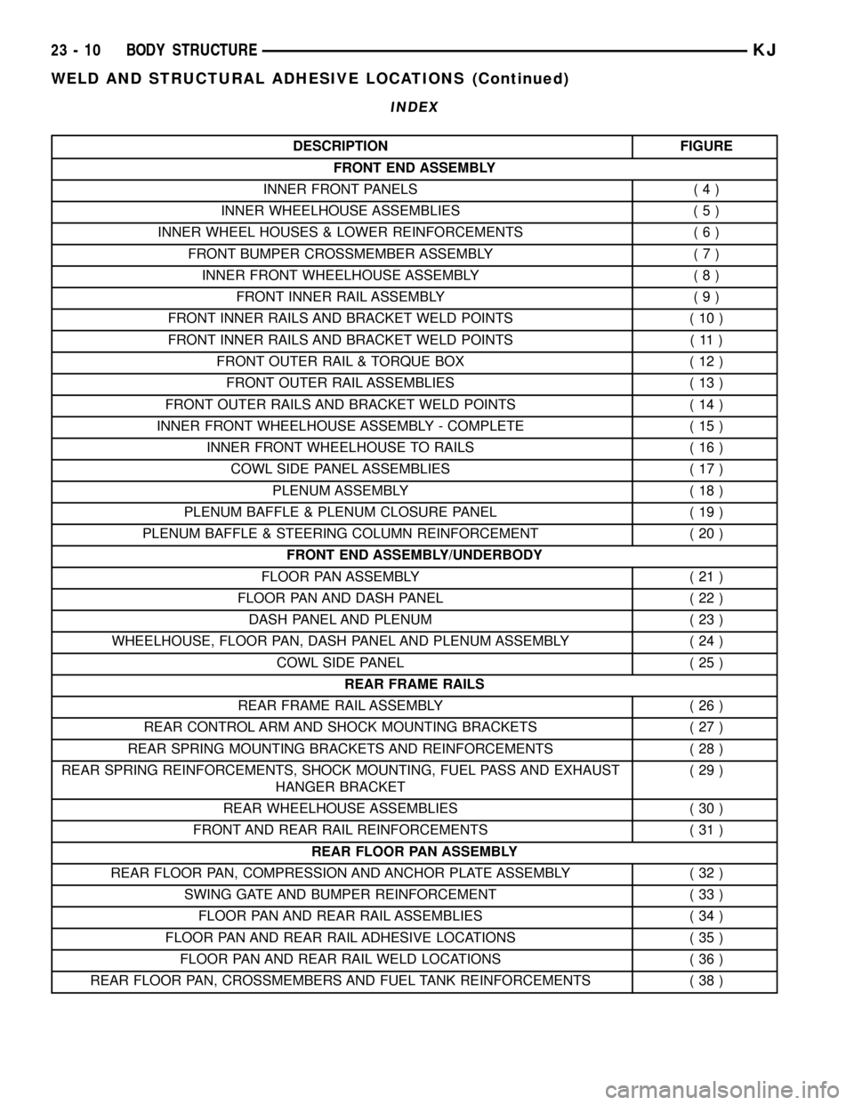
INDEX
DESCRIPTION FIGURE
FRONT END ASSEMBLY
INNER FRONT PANELS ( 4 )
INNER WHEELHOUSE ASSEMBLIES ( 5 )
INNER WHEEL HOUSES & LOWER REINFORCEMENTS ( 6 )
FRONT BUMPER CROSSMEMBER ASSEMBLY ( 7 )
INNER FRONT WHEELHOUSE ASSEMBLY ( 8 )
FRONT INNER RAIL ASSEMBLY ( 9 )
FRONT INNER RAILS AND BRACKET WELD POINTS ( 10 )
FRONT INNER RAILS AND BRACKET WELD POINTS ( 11 )
FRONT OUTER RAIL & TORQUE BOX ( 12 )
FRONT OUTER RAIL ASSEMBLIES ( 13 )
FRONT OUTER RAILS AND BRACKET WELD POINTS ( 14 )
INNER FRONT WHEELHOUSE ASSEMBLY - COMPLETE ( 15 )
INNER FRONT WHEELHOUSE TO RAILS ( 16 )
COWL SIDE PANEL ASSEMBLIES ( 17 )
PLENUM ASSEMBLY ( 18 )
PLENUM BAFFLE & PLENUM CLOSURE PANEL ( 19 )
PLENUM BAFFLE & STEERING COLUMN REINFORCEMENT ( 20 )
FRONT END ASSEMBLY/UNDERBODY
FLOOR PAN ASSEMBLY ( 21 )
FLOOR PAN AND DASH PANEL ( 22 )
DASH PANEL AND PLENUM ( 23 )
WHEELHOUSE, FLOOR PAN, DASH PANEL AND PLENUM ASSEMBLY ( 24 )
COWL SIDE PANEL ( 25 )
REAR FRAME RAILS
REAR FRAME RAIL ASSEMBLY ( 26 )
REAR CONTROL ARM AND SHOCK MOUNTING BRACKETS ( 27 )
REAR SPRING MOUNTING BRACKETS AND REINFORCEMENTS ( 28 )
REAR SPRING REINFORCEMENTS, SHOCK MOUNTING, FUEL PASS AND EXHAUST
HANGER BRACKET(29)
REAR WHEELHOUSE ASSEMBLIES ( 30 )
FRONT AND REAR RAIL REINFORCEMENTS ( 31 )
REAR FLOOR PAN ASSEMBLY
REAR FLOOR PAN, COMPRESSION AND ANCHOR PLATE ASSEMBLY ( 32 )
SWING GATE AND BUMPER REINFORCEMENT ( 33 )
FLOOR PAN AND REAR RAIL ASSEMBLIES ( 34 )
FLOOR PAN AND REAR RAIL ADHESIVE LOCATIONS ( 35 )
FLOOR PAN AND REAR RAIL WELD LOCATIONS ( 36 )
REAR FLOOR PAN, CROSSMEMBERS AND FUEL TANK REINFORCEMENTS ( 38 )
23 - 10 BODY STRUCTUREKJ
WELD AND STRUCTURAL ADHESIVE LOCATIONS (Continued)
Page 1503 of 1803

Fig. 29 REAR SPRING, SHOCK, FUEL PASS AND EXHAUST BRACKETS
23 - 38 BODY STRUCTUREKJ
WELD AND STRUCTURAL ADHESIVE LOCATIONS (Continued)
Page 1552 of 1803
SEALER LOCATIONS
SPECIFICATIONS
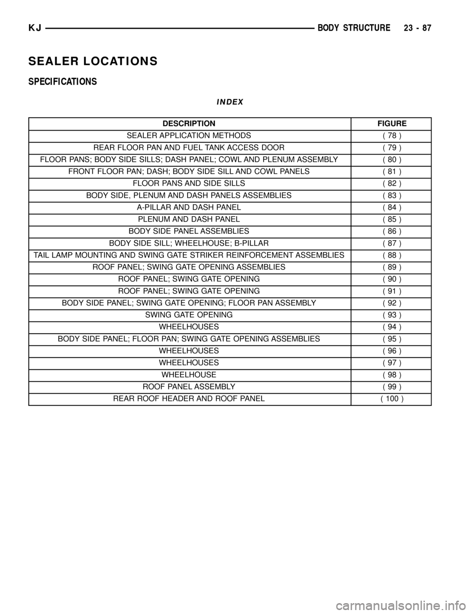
INDEX
DESCRIPTION FIGURE
SEALER APPLICATION METHODS ( 78 )
REAR FLOOR PAN AND FUEL TANK ACCESS DOOR ( 79 )
FLOOR PANS; BODY SIDE SILLS; DASH PANEL; COWL AND PLENUM ASSEMBLY ( 80 )
FRONT FLOOR PAN; DASH; BODY SIDE SILL AND COWL PANELS ( 81 )
FLOOR PANS AND SIDE SILLS ( 82 )
BODY SIDE, PLENUM AND DASH PANELS ASSEMBLIES ( 83 )
A-PILLAR AND DASH PANEL ( 84 )
PLENUM AND DASH PANEL ( 85 )
BODY SIDE PANEL ASSEMBLIES ( 86 )
BODY SIDE SILL; WHEELHOUSE; B-PILLAR ( 87 )
TAIL LAMP MOUNTING AND SWING GATE STRIKER REINFORCEMENT ASSEMBLIES ( 88 )
ROOF PANEL; SWING GATE OPENING ASSEMBLIES ( 89 )
ROOF PANEL; SWING GATE OPENING ( 90 )
ROOF PANEL; SWING GATE OPENING ( 91 )
BODY SIDE PANEL; SWING GATE OPENING; FLOOR PAN ASSEMBLY ( 92 )
SWING GATE OPENING ( 93 )
WHEELHOUSES ( 94 )
BODY SIDE PANEL; FLOOR PAN; SWING GATE OPENING ASSEMBLIES ( 95 )
WHEELHOUSES ( 96 )
WHEELHOUSES ( 97 )
WHEELHOUSE ( 98 )
ROOF PANEL ASSEMBLY ( 99 )
REAR ROOF HEADER AND ROOF PANEL ( 100 )
KJBODY STRUCTURE 23 - 87
Page 1605 of 1803

EXTERIOR
TABLE OF CONTENTS
page page
BODY SIDE MOLDINGS
REMOVAL............................140
INSTALLATION........................140
COWL GRILLE
REMOVAL............................140
INSTALLATION........................140
EXTERIOR NAME PLATES
REMOVAL............................140
INSTALLATION........................141
FRONT FENDER
REMOVAL............................141
INSTALLATION........................141
FUEL FILL DOOR/HOUSING
REMOVAL............................141
INSTALLATION........................141
GRILLE
REMOVAL............................142
INSTALLATION........................142
GRILLE OPENING REINFORCEMENT
REMOVAL............................142
INSTALLATION........................142FRONT WHEELHOUSE SPLASH SHIELD
REMOVAL............................143
INSTALLATION........................143
LUGGAGE RACK
REMOVAL............................144
INSTALLATION........................144
REAR WHEELHOUSE SPLASH SHIELD
REMOVAL............................144
INSTALLATION........................144
SIDE VIEW MIRROR
REMOVAL............................145
INSTALLATION........................145
FRONT WHEEL OPENING FLARE MOLDINGS
REMOVAL............................145
INSTALLATION........................145
REAR WHEEL OPENING FLARE MOLDINGS
REMOVAL............................145
INSTALLATION........................145
RADIATOR CROSSMEMBER
REMOVAL............................146
INSTALLATION........................146
BODY SIDE MOLDINGS
REMOVAL
(1) Using a trim stick C-4755 or equivalent,
remove and discard the molding from the outside of
the door.
INSTALLATION
(1) Thoroughly clean all residue from the body side
molding attachment area of the door.
(2) Wipe area clean with a 50% solution of water
and alcohol and wipe dry.
(3) Apply new body side molding using the locators
in the door and apply pressure of approximately 40
p.s.i. over the entire surface of the molding.
COWL GRILLE
REMOVAL
(1) Remove the hood seal.
(2) Remove the wiper arms. (Refer to 8 - ELEC-
TRICAL/WIPERS/WASHERS/WIPER ARMS -
REMOVAL)
(3) Remove the four plastic retainers and remove
the cowl grill.
INSTALLATION
(1) Position the cowl grill and engage the nine
clips to the bottom of the windshield.
(2) Install the five plastic retainers.
(3) Install the wiper arms. (Refer to 8 - ELECTRI-
CAL/WIPERS/WASHERS/WIPER ARMS - INSTAL-
LATION)
(4) Install the hood seal.
EXTERIOR NAME PLATES
REMOVAL
NOTE: Exterior nameplates are attached to body
panels with adhesive tape.
(1) Apply a length of masking tape on the body,
parallel to the top edge of the nameplate to use as a
guide, if necessary.
(2) If temperature is below 21ÉC (70ÉF) warm
emblem with a heat lamp or gun. Do not exceed 52ÉC
(120ÉF) when heating emblem.
(3) Using a trim stick C-4755 or equivalent, behind
the emblem to separate the adhesive backing from
the body.
23 - 140 EXTERIORKJ
Page 1606 of 1803
(4) Clean adhesive residue from body with MOPAR
Super Clean solvent or equivalent.
INSTALLATION
(1) Remove protective cover from adhesive tape on
back of emblem.
(2) Position emblem properly on body.
(3) Press emblem firmly to body with palm of
hand.
(4) If temperature is below 21ÉC (70ÉF) warm
emblem with a heat lamp or gun to assure adhesion.
Do not exceed 52ÉC (120ÉF) when heating emblem.
FRONT FENDER
REMOVAL
(1) Remove the wheel opening splash shield. (Refer
to 23 - BODY/EXTERIOR/FRONT WHEELHOUSE
SPLASH SHIELD - REMOVAL)
(2) Remove the fascia assembly. (Refer to 13 -
FRAME & BUMPERS/BUMPERS/FRONT FASCIA -
REMOVAL)
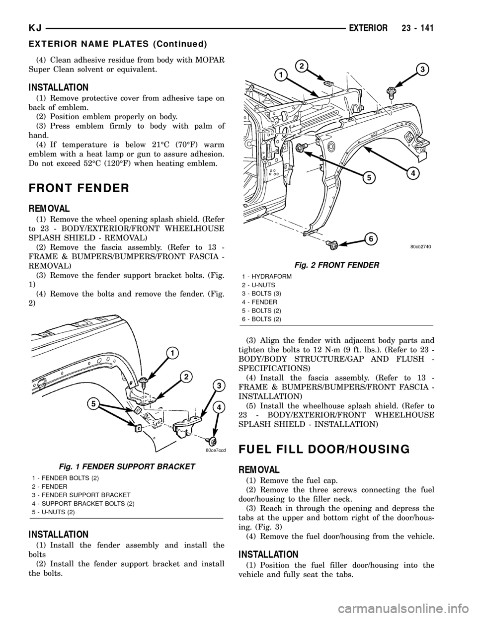
(3) Remove the fender support bracket bolts. (Fig.
1)
(4) Remove the bolts and remove the fender. (Fig.
2)
INSTALLATION
(1) Install the fender assembly and install the
bolts
(2) Install the fender support bracket and install
the bolts.(3) Align the fender with adjacent body parts and
tighten the bolts to 12 N´m (9 ft. lbs.). (Refer to 23 -
BODY/BODY STRUCTURE/GAP AND FLUSH -
SPECIFICATIONS)
(4) Install the fascia assembly. (Refer to 13 -
FRAME & BUMPERS/BUMPERS/FRONT FASCIA -
INSTALLATION)
(5) Install the wheelhouse splash shield. (Refer to
23 - BODY/EXTERIOR/FRONT WHEELHOUSE
SPLASH SHIELD - INSTALLATION)
FUEL FILL DOOR/HOUSING
REMOVAL
(1) Remove the fuel cap.
(2) Remove the three screws connecting the fuel
door/housing to the filler neck.
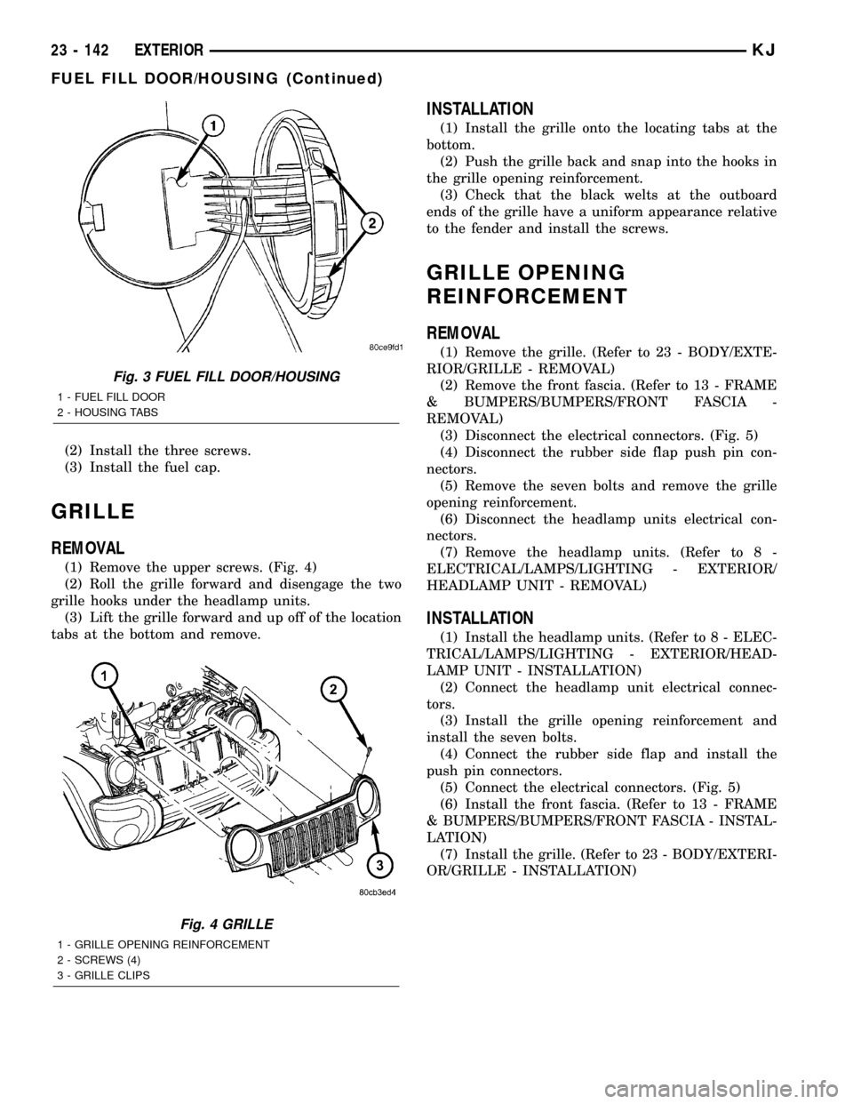
(3) Reach in through the opening and depress the
tabs at the upper and bottom right of the door/hous-
ing. (Fig. 3)
(4) Remove the fuel door/housing from the vehicle.
INSTALLATION
(1) Position the fuel filler door/housing into the
vehicle and fully seat the tabs.
Fig. 1 FENDER SUPPORT BRACKET
1 - FENDER BOLTS (2)
2 - FENDER
3 - FENDER SUPPORT BRACKET
4 - SUPPORT BRACKET BOLTS (2)
5 - U-NUTS (2)
Fig. 2 FRONT FENDER
1 - HYDRAFORM
2 - U-NUTS
3 - BOLTS (3)
4 - FENDER
5 - BOLTS (2)
6 - BOLTS (2)
KJEXTERIOR 23 - 141
EXTERIOR NAME PLATES (Continued)
Page 1607 of 1803
(2) Install the three screws.
(3) Install the fuel cap.
GRILLE
REMOVAL
(1) Remove the upper screws. (Fig. 4)
(2) Roll the grille forward and disengage the two
grille hooks under the headlamp units.
(3) Lift the grille forward and up off of the location
tabs at the bottom and remove.
INSTALLATION
(1) Install the grille onto the locating tabs at the
bottom.
(2) Push the grille back and snap into the hooks in
the grille opening reinforcement.
(3) Check that the black welts at the outboard
ends of the grille have a uniform appearance relative
to the fender and install the screws.
GRILLE OPENING
REINFORCEMENT
REMOVAL
(1) Remove the grille. (Refer to 23 - BODY/EXTE-
RIOR/GRILLE - REMOVAL)
(2) Remove the front fascia. (Refer to 13 - FRAME
& BUMPERS/BUMPERS/FRONT FASCIA -
REMOVAL)
(3) Disconnect the electrical connectors. (Fig. 5)
(4) Disconnect the rubber side flap push pin con-
nectors.
(5) Remove the seven bolts and remove the grille
opening reinforcement.
(6) Disconnect the headlamp units electrical con-
nectors.
(7) Remove the headlamp units. (Refer to 8 -
ELECTRICAL/LAMPS/LIGHTING - EXTERIOR/
HEADLAMP UNIT - REMOVAL)
INSTALLATION
(1) Install the headlamp units. (Refer to 8 - ELEC-
TRICAL/LAMPS/LIGHTING - EXTERIOR/HEAD-
LAMP UNIT - INSTALLATION)
(2) Connect the headlamp unit electrical connec-
tors.
(3) Install the grille opening reinforcement and
install the seven bolts.
(4) Connect the rubber side flap and install the
push pin connectors.
(5) Connect the electrical connectors. (Fig. 5)
(6) Install the front fascia. (Refer to 13 - FRAME
& BUMPERS/BUMPERS/FRONT FASCIA - INSTAL-
LATION)
(7) Install the grille. (Refer to 23 - BODY/EXTERI-
OR/GRILLE - INSTALLATION)
Fig. 3 FUEL FILL DOOR/HOUSING
1 - FUEL FILL DOOR
2 - HOUSING TABS
Fig. 4 GRILLE
1 - GRILLE OPENING REINFORCEMENT
2 - SCREWS (4)
3 - GRILLE CLIPS
23 - 142 EXTERIORKJ
FUEL FILL DOOR/HOUSING (Continued)
Page 1707 of 1803
EMISSIONS CONTROL
TABLE OF CONTENTS
page page
EMISSIONS CONTROL
DESCRIPTION
DESCRIPTION - EMISSION CONTROL
SYSTEM.............................1
DESCRIPTION - STATE DISPLAY TEST
MODE...............................2
DESCRIPTION - CIRCUIT ACTUATION TEST
MODE...............................2
DESCRIPTION - DIAGNOSTIC TROUBLE
CODES..............................2DESCRIPTION - TASK MANAGER.........17
DESCRIPTION - MONITORED SYSTEMS . . . 17
DESCRIPTION - TRIP DEFINITION........19
DESCRIPTION - COMPONENT MONITORS . . 19
DESCRIPTION - NON-MONITORED
CIRCUITS...........................20
DESCRIPTION - HIGH AND LOW LIMITS . . . 20
DESCRIPTION - LOAD VALUE...........20
OPERATION - TASK MANAGER............21
EVAPORATIVE EMISSIONS................24
EMISSIONS CONTROL
DESCRIPTION
DESCRIPTION - EMISSION CONTROL SYSTEM
The Powertrain Control Module (PCM) monitors
many different circuits in the fuel injection, ignition,
emission and engine systems. If the PCM senses a
problem with a monitored circuit often enough to
indicate an actual problem, it stores a Diagnostic
Trouble Code (DTC) in the PCM's memory. If the
code applies to a non-emissions related component or
system, and the problem is repaired or ceases to
exist, the PCM cancels the code after 40 warm-up
cycles. Diagnostic trouble codes that affect vehicle
emissions illuminate the Malfunction Indicator Lamp
(MIL). The MIL is displayed as an engine icon on the
instrument panel. Refer to Malfunction Indicator
Lamp (MIL) in this section.
Certain criteria must be met before the PCM
stores a DTC in memory. The criteria may be a spe-
cific range of engine RPM, engine temperature,
and/or input voltage to the PCM.
The PCM might not store a DTC for a monitored
circuit even though a malfunction has occurred. This
may happen because one of the DTC criteria for the
circuit has not been met.For example, assume the
diagnostic trouble code criteria requires the PCM to
monitor the circuit only when the engine operates
between 750 and 2000 RPM. Suppose the sensor's
output circuit shorts to ground when engine operates
above 2400 RPM (resulting in 0 volt input to the
PCM). Because the condition happens at an engine
speed above the maximum threshold (2000 rpm), the
PCM will not store a DTC.There are several operating conditions for which
the PCM monitors and sets DTC's. Refer to Moni-
tored Systems, Components, and Non-Monitored Cir-
cuits in this section.
Technicians must retrieve stored DTC's by connect-
ing the DRB scan tool (or an equivalent scan tool) to
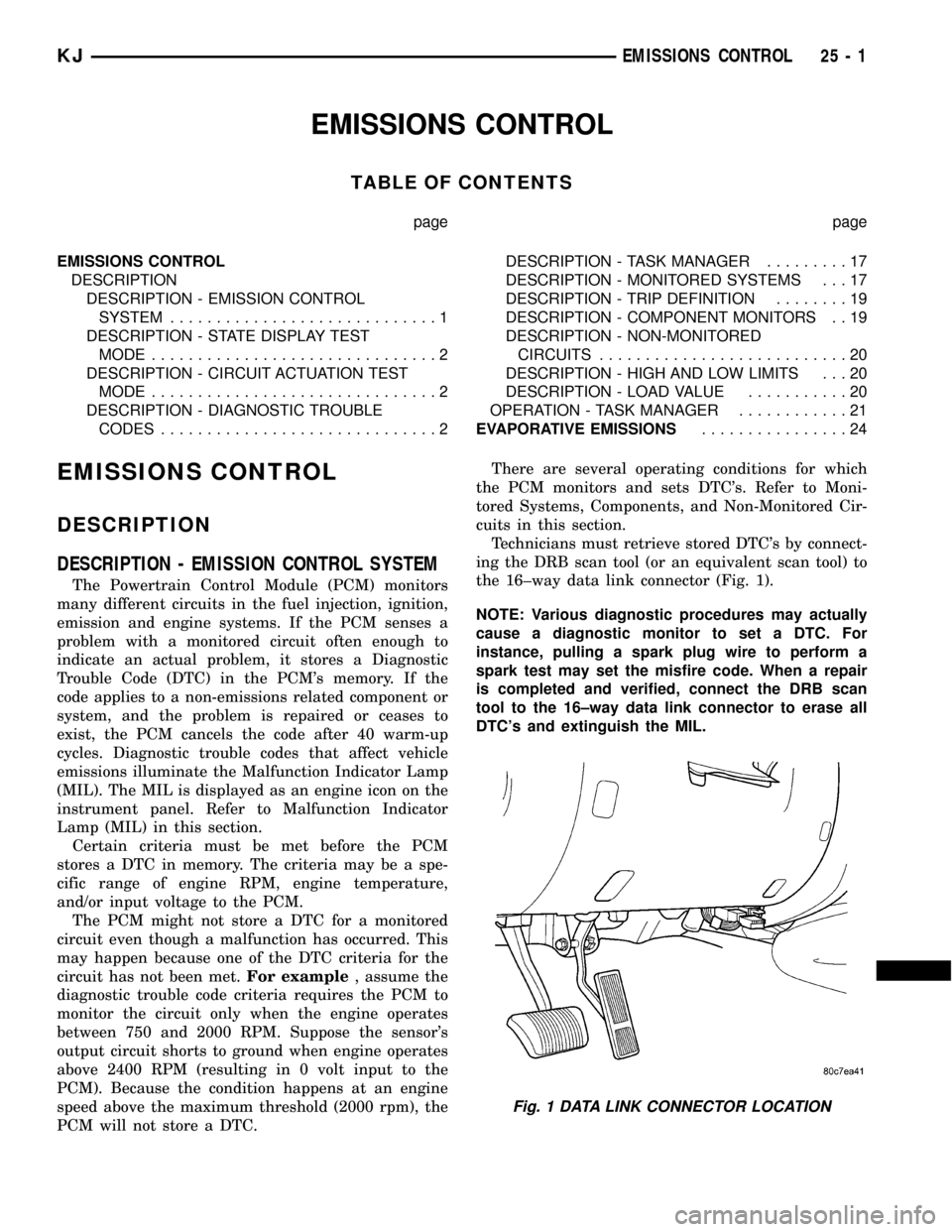
the 16±way data link connector (Fig. 1).
NOTE: Various diagnostic procedures may actually
cause a diagnostic monitor to set a DTC. For
instance, pulling a spark plug wire to perform a
spark test may set the misfire code. When a repair
is completed and verified, connect the DRB scan
tool to the 16±way data link connector to erase all
DTC's and extinguish the MIL.
Fig. 1 DATA LINK CONNECTOR LOCATION
KJEMISSIONS CONTROL 25 - 1