2002 JEEP LIBERTY Power steering fluid
[x] Cancel search: Power steering fluidPage 763 of 1803

Component Page
Low Beam Relay..................... 8Wa-50
Manifold Absolute Pressure Sensor....... 8Wa-30
Multi-Function Switch........... 8Wa-50, 52, 53
Output Speed Sensor.................. 8Wa-31
Overhead Map/Reading Lamp........... 8Wa-44
Oxygen Sensors...................... 8Wa-30
Oxygen Sensor Downstream Relay........ 8Wa-30
Park Brake Switch.................... 8Wa-40
Park Lamp Relay..................... 8Wa-50
Park/Turn Signal Lamps............ 8Wa-50, 52
Passenger Airbag..................... 8Wa-43
Passenger Door Unlock Relay........... 8Wa-61
Passenger Seat Belt Switch............. 8Wa-40
Position Lamps...................... 8Wa-50
Power Distribution Center.............. 8Wa-10
Power Mirrors....................... 8Wa-62
Power Outlet........................ 8Wa-41
Power Seats......................... 8Wa-63
Power Steering Pressure Switch......... 8Wa-30
Power Windows...................... 8Wa-60
Powertrain Control Module............. 8Wa-30
Radiator Fans....................... 8Wa-30
Radio Choke......................... 8Wa-47
Radio.............................. 8Wa-47
Rear Fog Lamp Relay................. 8Wa-51
Rear Power Outlet.................... 8Wa-41
Rear Power Window Switch............. 8Wa-60
Rear Wheel Speed Sensor.............. 8Wa-35
Rear Window Defogger................. 8Wa-48
Rear Wiper Motor.................... 8Wa-53
Red Brake Warning Indicator Switch...... 8Wa-40Component Page
Remote Keyless Entry Module........... 8Wa-45
Remote Radio Switches................ 8Wa-47
Splices............................. 8Wa-10
Sentry Key Immobilizer Module.......... 8Wa-39
Shifter Assembly..................... 8Wa-31
Side Impact Airbag Control Modules...... 8Wa-43
Side Marker Lamps................ 8Wa-50, 52
Side Repeater Lamps............... 8Wa-50, 52
Siren.............................. 8Wa-49
Speed Control Servo................... 8Wa-33
Speed Control Switches................ 8Wa-33
Starter Motor Relay................... 8Wa-21
Starter Motor........................ 8Wa-21
Sunroof............................ 8Wa-64
Tail/Stop Lamps...................... 8Wa-51
Tailgate Cylinder Lock Switch........... 8Wa-61
Tailgate Flip-Up Ajar Switch............ 8Wa-61
Tailgate Lock Motor/Ajar Switch......... 8Wa-61
Throttle Position Sensor................ 8Wa-30
Trailer Tow.......................... 8Wa-54
Transfer Case Position Sensor........ 8Wa-30, 31
Transmission Control Module........... 8Wa-31
Transmission Control Relay............. 8Wa-31
Transmission Solenoid/TRS Assembly..... 8Wa-31
Visor/Vanity Lamps................... 8Wa-44
Washer Fluid Level Switch............. 8Wa-53
Washer Pump........................ 8Wa-53
Water In Fuel Sensor.................. 8Wa-30
Wheel Speed Sensors.................. 8Wa-35
Wiper High/Low Relay................. 8Wa-53
KJ8W-02 COMPONENT INDEX8Wa-02-1
Page 830 of 1803

8W-15 GROUND DISTRIBUTION
Component Page
A/C Compressor Clutch...................8Wa-15-6
A/C Low Pressure Switch.................8Wa-15-3
A/C- Heater Control...................8Wa-15-7, 8
Airbag Control Module...................8Wa-15-7
Ash Receiver Lamp.....................8Wa-15-8
Battery.............................8Wa-15-2
Blend Door Actuator.....................8Wa-15-8
Blower Motor Relay.....................8Wa-15-4
Body Control Module....................8Wa-15-8
Brake Lamp Switch.....................8Wa-15-8
Cabin Heater.........................8Wa-15-6
Capacitor............................8Wa-15-2
Center High Mounted Stop Lamp...........8Wa-15-14
Cigar Lighter.........................8Wa-15-8
Compass Mini-Trip Computer..............8Wa-15-14
Controller Antilock Brake.................8Wa-15-2
Data Link Connector....................8Wa-15-2
Engine Control Module...................8Wa-15-7
Engine Coolant Level Sensor...............8Wa-15-6
Flip-Up Glass Release Motor..............8Wa-15-14
Front Wiper Motor......................8Wa-15-3
Fuel Heater..........................8Wa-15-6
Fuel Heater Relay......................8Wa-15-4
Fuel Pump Module.....................8Wa-15-15
G100.............................8Wa-15-2, 7
G101...............................8Wa-15-6
G102...............................8Wa-15-2
G103...............................8Wa-15-6
G104...............................8Wa-15-7
G105...............................8Wa-15-2
G106...............................8Wa-15-2
G110...............................8Wa-15-2
G111 .............................8Wa-15-3, 4
G112...............................8Wa-15-3
G200...............................8Wa-15-7
G201...............................8Wa-15-7
G202...............................8Wa-15-8
G300............................8Wa-15-9, 11
G301............................8Wa-15-9, 10
G302............................8Wa-15-9, 12
G310.........................8Wa-15-13, 14, 15
G311 ..............................8Wa-15-14
G312..............................8Wa-15-14
G320..............................8Wa-15-15
Hazard Switch/Combination Flasher..........8Wa-15-8
Headlamp Leveling Switch................8Wa-15-8
Heated Seat Module....................8Wa-15-10
High Note Horn.......................8Wa-15-3
Hood Ajar Switch.......................8Wa-15-4
Ignition Switch........................8Wa-15-8
Instrument Cluster.....................8Wa-15-8
Intrusion Sensor......................8Wa-15-14
Junction Block........................8Wa-15-8
Left Door Lock Switch...................8Wa-15-11
Left Fog Lamp........................8Wa-15-5
Left Front Door Ajar Switch...............8Wa-15-11
Left Front Door Lock Motor/Ajar Switch.......8Wa-15-11
Left Front Door Speaker..................8Wa-15-7
Left Front Park/Turn Signal Lamp...........8Wa-15-5
Left Headlamp........................8Wa-15-3
Left Heated Seat Assembly...............8Wa-15-10
Left Heated Seat Switch.................8Wa-15-10Component Page
Left Leveling Motor.....................8Wa-15-3
Left Position Lamp.....................8Wa-15-3
Left Power Mirror.....................8Wa-15-11
Left Power Seat Switch..................8Wa-15-10
Left Rear Door Ajar Switch...............8Wa-15-11
Left Rear Door Lock Motor/Ajar Switch.......8Wa-15-11
Left Side Impact Airbag Control Module........8Wa-15-9
Left Side Repeater Lamp..................8Wa-15-5
Left Tail/Stop Lamp....................8Wa-15-15
License Lamp........................8Wa-15-15
Line Pressure Sensor....................8Wa-15-2
Low Note Horn........................8Wa-15-3
Multi- Function Switch...................8Wa-15-8
Oxygen Sensor 1/2 Downstream.............8Wa-15-6
Oxygen Sensor 2/2 Downstream.............8Wa-15-6
Power Mirror Switch.................8Wa-15-11, 12
Power Outlet.........................8Wa-15-8
Power Steering Pressure Switch.............8Wa-15-6
Power Window Master Switch.............8Wa-15-10
Powertrain Control Module................8Wa-15-2
Radiator Fan Motor.....................8Wa-15-3
Radiator Fan Relay.....................8Wa-15-3
Radio..............................8Wa-15-7
Radio Choke..........................8Wa-15-9
Rear Power Outlet.....................8Wa-15-15
Rear Window Defogger..................8Wa-15-14
Rear Wiper Motor.....................8Wa-15-14
Red Brake Warning Indicator Switch..........8Wa-15-4
Right Door Lock Switch..................8Wa-15-12
Right Fog Lamp.......................8Wa-15-5
Right Front Door Ajar Switch..............8Wa-15-12
Right Front Door Lock Motor/Ajar Switch......8Wa-15-12
Right Front Door Speaker.................8Wa-15-7
Right Front Park/Turn Signal Lamp..........8Wa-15-5
Right Headlamp.......................8Wa-15-4
Right Heated Seat Assembly..............8Wa-15-10
Right Heated Seat Switch................8Wa-15-10
Right Leveling Motor....................8Wa-15-4
Right Position Lamp....................8Wa-15-4
Right Power Mirror....................8Wa-15-12
Right Power Seat Switch.................8Wa-15-10
Right Rear Door Ajar Switch..............8Wa-15-12
Right Rear Door Lock Motor/Ajar Switch......8Wa-15-12
Right Side Impact Airbag Control Module.......8Wa-15-9
Right Side Repeater Lamp.................8Wa-15-5
Right Tail/Stop Lamp...................8Wa-15-15
Sentry Key Immobilizer Module.............8Wa-15-8
Shifter Assembly.......................8Wa-15-9
Siren...............................8Wa-15-4
Speed Control Servo.....................8Wa-15-3
Starter Motor Relay.....................8Wa-15-4
Sunroof Motor........................8Wa-15-14
Tailgate Flip-Up Ajar Switch..............8Wa-15-14
Trailer Tow Brake Lamp Relay.............8Wa-15-13
Trailer Tow Connector...................8Wa-15-13
Trailer Tow Left Turn Relay...............8Wa-15-13
Trailer Tow Relay......................8Wa-15-13
Trailer Tow Right Turn Relay..............8Wa-15-13
Transmission Control Module...............8Wa-15-2
Transmission Control Relay................8Wa-15-4
Washer Fluid Level Switch................8Wa-15-3
KJ8W-15 GROUND DISTRIBUTION8Wa-15-1
Page 1431 of 1803
STEERING
TABLE OF CONTENTS
page page
STEERING
DESCRIPTION..........................1
OPERATION............................1
DIAGNOSIS AND TESTING
DIAGNOSIS AND TESTING - POWER
STEERING SYSTEM....................1DIAGNOSIS AND TESTING - POWER
STEERING FLOW AND PRESSURE........3
COLUMN...............................5
GEAR.................................13
LINKAGE..............................16
PUMP.................................17
STEERING
DESCRIPTION
Power steering systems consist of:
²Steering column & Intermediate Shaft
²Rack and pinion steering gear
²Belt driven hydraulic steering pump
²Pump pressure, supply and return hoses
²Oil Cooler
OPERATION
The steering column intermediate shaft attaches
the steering column to the gear pinion. The rotation
of the pinion moves the gear rack from side-to-side.
This lateral action of the rack pushes and pulls the
tie rods to change the direction of the front wheels.
Power assist is provided by an engine mounted
hydraulic pump. The pump supplies hydraulic fluid
to the steering gear. All vehicles are equipped with
an oil cooler.
DIAGNOSIS AND TESTING
DIAGNOSIS AND TESTING - POWER STEERING SYSTEM
STEERING NOISE
There is some noise in all power steering systems. One of the most common is a hissing sound evident at a
standstill/parking, or when the steering is at the end of it's travel. Hiss is a high frequency noise similar to that
of a water tap being closed slowly. The noise is present in all valves that have a high velocity fluid passing through
an orifice. There is no relationship between this noise and steering performance.
CONDITION POSSIBLE CAUSES CORRECTION
OBJECTIONAL HISS OR
WHISTLE1. Steering intermediate shaft to dash panel
seal.1. Check and repair seal at dash
panel.
2. Noisy valve in power steering gear. 2. Replace steering gear.
1. Gear mounting bolts loose. 1. Tighten bolts to specification.
2. Loose or damaged suspension
components.2. Inspect and repair suspension.
3. Internal gear noise. 3. Replace steering gear.
4. Loose or damaged intermediate shaft or
column.4. Inspect and repair or replace.
MOAN Pressure hose in contact with other
components.Reposition hose.
CHIRP OR SQUEAL 1. Loose belt. 1. Adjust or replace.
KJSTEERING 19 - 1
Page 1433 of 1803
LOOSE STEERING AND VEHICLE LEAD
CONDITION POSSIBLE CAUSE CORRECTION
EXCESSIVE PLAY IN STEERING
WHEEL1. Worn or loose suspension or
steering components.1. Inspect and repair as necessary.
2. Worn or loose wheel bearings. 2. Inspect and replace bearings.
3. Steering gear mounting. 3. Tighten / replace gear mounting
bolts/ isolators to specification.
4. Gear out of adjustment. 4. Replace gear.
5. Worn or loose steering
intermediate shaft.5. Inspect and replace as
necessary.
VEHICLE PULLS, DRIFTS OR
LEADS TO ONE SIDE.1. Tire Pressure. 1. Adjust tire pressure.
2. Radial tire lead. 2. Rotate tires.
3. Brakes dragging. 3. Repair as necessary.
4. Wheel alignment. 4. Align front end.
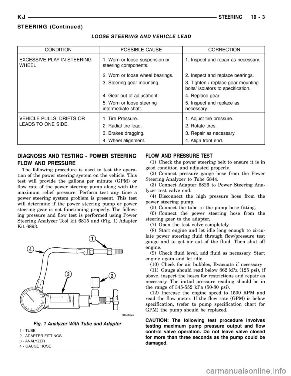
DIAGNOSIS AND TESTING - POWER STEERING
FLOW AND PRESSURE
The following procedure is used to test the opera-
tion of the power steering system on the vehicle. This
test will provide the gallons per minute (GPM) or
flow rate of the power steering pump along with the
maximum relief pressure. Perform test any time a
power steering system problem is present. This test
will determine if the power steering pump or power
steering gear is not functioning properly. The follow-
ing pressure and flow test is performed using Power
Steering Analyzer Tool kit 6815 and (Fig. 1) Adapter
Kit 6893.
FLOW AND PRESSURE TEST
(1) Check the power steering belt to ensure it is in
good condition and adjusted properly.
(2) Connect pressure gauge hose from the Power
Steering Analyzer to Tube 6844.
(3) Connect Adapter 6826 to Power Steering Ana-
lyzer test valve end.
(4) Disconnect the high pressure hose from the
power steering pump.
(5) Connect the tube to the pump hose fitting.
(6) Connect the power steering hose from the
steering gear to the adapter.
(7) Open the test valve completely.
(8) Start engine and let idle long enough to circu-
late power steering fluid through flow/pressure test
gauge and to get air out of the fluid. Then shut off
engine.
(9) Check fluid level, add fluid as necessary. Start
engine again and let idle.
(10) Check for air bubbles, Evacuate if necessary
(11) Gauge should read below 862 kPa (125 psi), if
above, inspect the hoses for restrictions and repair as
necessary. The initial pressure reading should be in
the range of 345-552 kPa (50-80 psi).
(12) Increase the engine speed to 1500 RPM and
read the flow meter. If the flow rate (GPM) is below
specification, (refer to pump specification chart for
GPM) the pump should be replaced.
CAUTION: The following test procedure involves
testing maximum pump pressure output and flow
control valve operation. Do not leave valve closed
for more than three seconds as the pump could be
damaged.
Fig. 1 Analyzer With Tube and Adapter
1 - TUBE
2 - ADAPTER FITTINGS
3 - ANALYZER
4 - GAUGE HOSE
KJSTEERING 19 - 3
STEERING (Continued)
Page 1443 of 1803
GEAR
TABLE OF CONTENTS
page page
GEAR
DESCRIPTION.........................13
OPERATION...........................13
REMOVAL
REMOVAL - 4WD......................13
REMOVAL - 2WD......................14
INSTALLATION
INSTALLATION - 4WD..................14INSTALLATION - 2WD..................14
SPECIFICATIONS
TORQUE CHART......................15
SPECIAL TOOLS
OUTER TIE ROD END REMOVAL TOOL....15
GEAR
DESCRIPTION
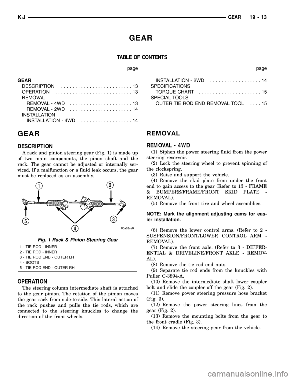
A rack and pinion steering gear (Fig. 1) is made up
of two main components, the pinon shaft and the
rack. The gear cannot be adjusted or internally ser-
viced. If a malfunction or a fluid leak occurs, the gear
must be replaced as an assembly.
OPERATION
The steering column intermediate shaft is attached
to the gear pinion. The rotation of the pinion moves
the gear rack from side-to-side. This lateral action of
the rack pushes and pulls the tie rods, which are
connected to the steering knuckles to change the
direction of the front wheels.
REMOVAL
REMOVAL - 4WD
(1) Siphon the power steering fluid from the power
steering reservoir.
(2) Lock the steering wheel to prevent spinning of
the clockspring.
(3) Raise and support the vehicle.
(4) Remove the skid plate from under the front
end to gain access to the gear (Refer to 13 - FRAME
& BUMPERS/FRAME/FRONT SKID PLATE -
REMOVAL).
(5) Remove the front tire and wheel assemblies.
NOTE: Mark the alignment adjusting cams for eas-
ier installation.
(6) Remove the lower control arms. (Refer to 2 -
SUSPENSION/FRONT/LOWER CONTROL ARM -
REMOVAL).
(7) Remove the front axle. (Refer to 3 - DIFFER-
ENTIAL & DRIVELINE/FRONT AXLE - REMOV-
AL).
(8) Remove the tie rod end nuts.
(9) Separate tie rod ends from the knuckles with
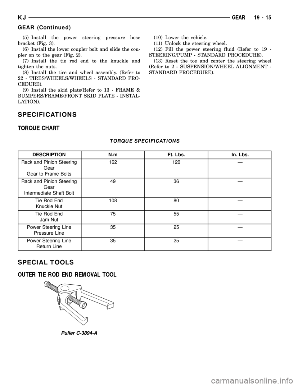
Puller C-3894-A.
(10) Remove the intermediate shaft lower coupler
bolt and slide the coupler off the gear (Fig. 2).
(11) Remove power steering pressure hose bracket
(Fig. 3).
(12) Remove the power steering lines from the
gear (Fig. 2).
(13) Remove the mounting bolts from the gear to
the front cradle (Fig. 3).
(14) Remove the steering gear from the vehicle.
Fig. 1 Rack & Pinion Steering Gear
1 - TIE ROD - INNER
2 - TIE ROD - INNER
3 - TIE ROD END - OUTER LH
4 - BOOTS
5 - TIE ROD END - OUTER RH
KJGEAR 19 - 13
Page 1444 of 1803

REMOVAL - 2WD
(1) Siphon the power steering fluid from the power
steering reservoir.
(2) Lock the steering wheel to prevent spinning of
the clockspring.
(3) Raise and support the vehicle.
(4) Remove the skid plate from under the front
end to gain access to the gear(Refer to 13 - FRAME
& BUMPERS/FRAME/FRONT SKID PLATE -
REMOVAL).
(5) Remove the tire and wheel assembly.
NOTE: Mark the alignment adjusting cams and tie
rod end jam nuts on the steering gear for easier
installation.
(6) Remove the tie rod end nuts.
(7) Separate tie rod ends from the knuckles with
Puller C-3894-A.
(8) Remove the lower intermediate shaft coupler
bolt and slide the coupler off the gear (Fig. 2).(9) Remove power steering pressure hose bracket
(Fig. 3).
(10) Remove the power steering lines from the
gear (Fig. 2).
(11) Remove the mounting bolts from the gear to
the front cradle (Fig. 3).
(12) Remove the steering gear from the vehicle.
INSTALLATION
INSTALLATION - 4WD
(1) Transfer the tie rod ends to the new steering
gear (if needed).
(2) Install the steering gear to the vehicle.
(3) Install the gear mounting bolts to the front cra-
dle. (Fig. 3). Tighten the gear mounting bolts to 162
N´m (120 ft.lbs.)
(4) Install the power steering lines to the gear
(Fig. 2).
(5) Install the power steering pressure hose
bracket (Fig. 3).
(6) Install the lower coupler bolt and slide the cou-
pler on to the gear (Fig. 2).
(7) Install the tie rod end to the knuckle and
tighten the nuts.
(8) Install the front axle. (Refer to 3 - DIFFEREN-
TIAL & DRIVELINE/FRONT AXLE - INSTALLA-
TION).
(9) Install the lower control arms. (Refer to 2 -
SUSPENSION/FRONT/LOWER CONTROL ARM -
INSTALLATION).
(10) Install the tire and wheel assembly. (Refer to
22 - TIRES/WHEELS/WHEELS - STANDARD PRO-
CEDURE).
(11) Install the skid plate (Refer to 13 - FRAME &
BUMPERS/FRAME/FRONT SKID PLATE - INSTAL-
LATION).
(12) Lower the vehicle.
(13) Unlock the steering wheel.
(14) Fill the power steering fluid (Refer to 19 -
STEERING/PUMP - STANDARD PROCEDURE).
(15) Reset the toe and center the steering wheel
(Refer to 2 - SUSPENSION/WHEEL ALIGNMENT -
STANDARD PROCEDURE).
INSTALLATION - 2WD
(1) Transfer the outer tie rod ends to the new
steering gear (if needed).
(2) Install the steering gear to the vehicle.
(3) Install the gear mounting bolts to the front cra-
dle. (Fig. 3). Tighten the gear mounting bolts to 162
N´m (120 ft.lbs.)
(4) Install the power steering lines to the gear
(Fig. 2).
Fig. 2 COUPLER BOLT
Fig. 3 RACK & PINION
19 - 14 GEARKJ
GEAR (Continued)
Page 1445 of 1803
(5) Install the power steering pressure hose
bracket (Fig. 3).
(6) Install the lower coupler bolt and slide the cou-
pler on to the gear (Fig. 2).
(7) Install the tie rod end to the knuckle and
tighten the nuts.
(8) Install the tire and wheel assembly. (Refer to
22 - TIRES/WHEELS/WHEELS - STANDARD PRO-
CEDURE).
(9) Install the skid plate(Refer to 13 - FRAME &
BUMPERS/FRAME/FRONT SKID PLATE - INSTAL-
LATION).(10) Lower the vehicle.
(11) Unlock the steering wheel.
(12) Fill the power steering fluid (Refer to 19 -
STEERING/PUMP - STANDARD PROCEDURE).
(13) Reset the toe and center the steering wheel
(Refer to 2 - SUSPENSION/WHEEL ALIGNMENT -
STANDARD PROCEDURE).
SPECIFICATIONS
TORQUE CHART
TORQUE SPECIFICATIONS
DESCRIPTION N´m Ft. Lbs. In. Lbs.
Rack and Pinion Steering
Gear
Gear to Frame Bolts162 120 Ð
Rack and Pinion Steering
Gear
Intermediate Shaft Bolt49 36 Ð
Tie Rod End
Knuckle Nut108 80 Ð
Tie Rod End
Jam Nut75 55 Ð
Power Steering Line
Pressure Line35 25 Ð
Power Steering Line
Return Line35 25 Ð
SPECIAL TOOLS
OUTER TIE ROD END REMOVAL TOOL
Puller C-3894-A
KJGEAR 19 - 15
GEAR (Continued)
Page 1447 of 1803
PUMP
TABLE OF CONTENTS
page page
PUMP
DESCRIPTION.........................17
OPERATION...........................17
STANDARD PROCEDURE - POWER
STEERING PUMP - INITIAL OPERATION....18
REMOVAL
REMOVAL - 3.7L......................18
REMOVAL - 2.4L......................18
INSTALLATION
INSTALLATION - 3.7L..................19
INSTALLATION - 2.4L..................19
SPECIFICATIONS
TORQUE CHART......................19
SPECIAL TOOLS
POWER STEERING PUMP..............20
FLUID COOLER
DESCRIPTION.........................20
OPERATION...........................20
REMOVAL.............................20
INSTALLATION.........................20
HOSES
REMOVAL
REMOVAL - PRESSURE HOSE...........21
REMOVAL - RETURN HOSE (GEAR TO THE
COOLER)...........................21REMOVAL - RETURN HOSE (RESERVOIR
TO THE COOLER).....................21
INSTALLATION
INSTALLATION - PRESSURE HOSE.......21
INSTALLATION - RETURN HOSE (GEAR TO
THE COOLER)........................22
INSTALLATION - RETURN HOSE
(RESERVOIR TO THE COOLER)..........22
POWER STEERING PRESSURE SWITCH
DESCRIPTION.........................22
OPERATION...........................22
REMOVAL.............................22
INSTALLATION.........................22
PULLEY
REMOVAL.............................23
INSTALLATION.........................23
RESERVOIR
REMOVAL
REMOVAL - 3.7L......................24
REMOVAL - 2.4L......................24
INSTALLATION
INSTALLATION - 3.7L..................24
INSTALLATION - 2.4L..................24
PUMP
DESCRIPTION
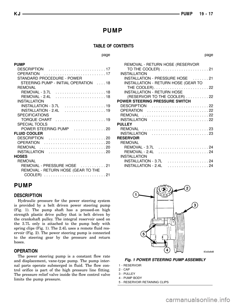
Hydraulic pressure for the power steering system
is provided by a belt driven power steering pump
(Fig. 1). The pump shaft has a pressed-on high
strength plastic drive pulley that is belt driven by
the crankshaft pulley. The integral reservoir used on
the 3.7L only is attached to the pump body with
spring clips (Fig. 1). The 2.4L uses a remote fluid res-
ervoir (Fig. 2). The power steering pump is connected
to the steering gear by the pressure and return
hoses.
OPERATION
The power steering pump is a constant flow rate
and displacement, vane-type pump. The pump inter-
nal parts operate submerged in fluid. The flow con-
trol orifice is part of the high pressure line fitting.
The pressure relief valve inside the flow control valve
limits the pump pressure.Fig. 1 POWER STEERING PUMP ASSEMBLY
1 - RESERVOIR
2 - CAP
3 - PULLEY
4 - PUMP BODY
5 - RESERVOIR RETAINING CLIPS
KJPUMP 19 - 17