2002 JEEP LIBERTY Main Bearings
[x] Cancel search: Main BearingsPage 108 of 1803

(8) Thread Pilot Stud C-3288-B into rear cover bolt
hole below ring gear (Fig. 19).
(9) Attach Dial Indicator C-3339 to the pilot stud
and position indicator plunger on a flat surface of the
ring gear bolt head (Fig. 19).
(10) Push the differential case firmly to the pinion
gear side of the housing (Fig. 20) and zero dial indi-
cator.
(11) Push differential case firmly to the ring gear
side and record dial indicator reading (Fig. 21).
(12) Add the dial indicator reading to the starting
point shim thickness to determine total shim thick-
ness to achieve zero differential end play.
(13) Add 0.2 mm (0.008 in.) to the zero end play
total. This new total represents the thickness of
shims to compress or preload the new bearings when
the differential is installed.
(14) Rotate dial indicator out of the way.
(15) Remove differential case, dummy bearings
and starting point shims from the housing.
(16) Install pinion gear in the housing. Install the
yoke and establish the correct pinion rotating torque.
(17) Install differential case and dummy bearings
in the housing (without shims) and tighten retaining
cap bolts.
(18) Position the dial indicator plunger on a flat
surface between the ring gear bolt heads (Fig. 19).(19) Push and hold differential case toward pinion
gear.
(20) Zero dial indicator face to pointer.
(21) Push and hold differential case to ring gear
side of the housing and record dial indicator reading.
(22) Subtract 0.05 mm (0.002 in.) from the dial
indicator reading to compensate for backlash between
ring and pinion gears. This total is the thickness of
shim required to achieve proper backlash.
(23) Subtract the backlash shim thickness from
the total preload shim thickness. The remainder is
the shim thickness required on the pinion side of the
housing.
Fig. 19 DIFFERENTIAL SIDE PLAY
1 - DIFFERENTIAL CASE
2 - DIFFERENTIAL HOUSING
3 - PILOT STUD
4 - DIAL INDICATOR
Fig. 20 ZERO DIAL INDICATOR
1 - FORCE CASE TO PINION SIDE
2 - PILOT STUD
3 - DIAL INDICATOR EXTENSION
4 - DIAL INDICATOR
Fig. 21 RECORD DIAL INDICATOR
1 - DIAL INDICATOR
2 - FORCE CASE TO RING GEAR SIDE
3 - DIFFERENTIAL HOUSING
KJREAR AXLE - 198RBI 3 - 59
REAR AXLE - 198RBI (Continued)
Page 122 of 1803

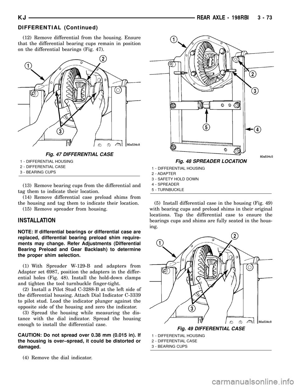
(12) Remove differential from the housing. Ensure
that the differential bearing cups remain in position
on the differential bearings (Fig. 47).
(13) Remove bearing cups from the differential and
tag them to indicate their location.
(14) Remove differential case preload shims from
the housing and tag them to indicate their location.
(15) Remove spreader from housing.
INSTALLATION
NOTE: If differential bearings or differential case are
replaced, differential bearing preload shim require-
ments may change. Refer Adjustments (Differential
Bearing Preload and Gear Backlash) to determine
the proper shim selection.
(1) With Spreader W-129-B and adapters from
Adapter set 6987, position the adapters in the differ-
ential holes (Fig. 48). Install the hold-down clamps
and tighten the tool turnbuckle finger-tight.
(2) Install a Pilot Stud C-3288-B at the left side of
the differential housing. Attach Dial Indicator C-3339
to pilot stud. Load the indicator plunger against the
opposite side of the housing and zero the indicator.
(3) Spread the housing while measuring the dis-
tance with the dial indicator. Spread the housing
enough to install the differential case.
CAUTION: Do not spread over 0.38 mm (0.015 in). If
the housing is over±spread, it could be distorted or
damaged.
(4) Remove the dial indicator.(5) Install differential case in the housing (Fig. 49)
with bearing cups and preload shims in their original
locations. Tap the differential case to ensure the
bearings cups and shims are fully seated in the hous-
ing.
Fig. 47 DIFFERENTIAL CASE
1 - DIFFERENTIAL HOUSING
2 - DIFFERENTIAL CASE
3 - BEARING CUPSFig. 48 SPREADER LOCATION
1 - DIFFERENTIAL HOUSING
2 - ADAPTER
3 - SAFETY HOLD DOWN
4 - SPREADER
5 - TURNBUCKLE
Fig. 49 DIFFERENTIAL CASE
1 - DIFFERENTIAL HOUSING
2 - DIFFERENTIAL CASE
3 - BEARING CUPS
KJREAR AXLE - 198RBI 3 - 73
DIFFERENTIAL (Continued)
Page 135 of 1803

REAR AXLE-81/4
TABLE OF CONTENTS
page page
REAR AXLE-81/4
DESCRIPTION.........................86
OPERATION...........................86
DIAGNOSIS AND TESTING - AXLE..........88
REMOVAL.............................91
INSTALLATION.........................91
ADJUSTMENTS........................92
SPECIFICATIONS
REAR AXLE..........................98
SPECIAL TOOLS
8 1/4 AXLE..........................98
AXLE SHAFTS
REMOVAL............................101
INSTALLATION........................101
AXLE SHAFT SEALS
REMOVAL............................101
INSTALLATION........................102
AXLE BEARINGS
REMOVAL............................102
INSTALLATION........................102PINION SEAL
REMOVAL............................102
INSTALLATION........................103
DIFFERENTIAL
REMOVAL............................104
DISASSEMBLY........................105
ASSEMBLY...........................105
INSTALLATION........................105
DIFFERENTIAL - TRAC-LOK
DIAGNOSIS AND TESTING - TRAC-LOKT....106
DISASSEMBLY........................107
CLEANING...........................109
INSPECTION.........................109
ASSEMBLY...........................109
DIFFERENTIAL CASE BEARINGS
REMOVAL............................110
INSTALLATION........................110
PINION GEAR/RING GEAR/TONE RING
REMOVAL............................110
INSTALLATION........................112
REAR AXLE-81/4
DESCRIPTION
The axle housings consist of a cast iron center sec-
tion with axle tubes extending from either side. The
tubes are pressed into and welded to the differential
housing to form a one-piece axle housing. The axles
are equipped with semi-floating axle shafts, meaning
vehicle loads are supported by the axle shaft and
bearings. The axle shafts are retained by C-locks in
the differential side gears.
The differential case is a one-piece design. The dif-
ferential pinion mate shaft is retained with a
threaded pin. Differential bearing preload and ring
gear backlash are set and maintained by threaded
adjusters at the outside of the differential housing.
Pinion bearing preload is set and maintained by the
use of a collapsible spacer.
The differential cover provides a means for inspec-
tion and service without removing the complete axlefrom the vehicle. A vent hose is used to relieve inter-
nal pressure caused by lubricant vaporization and
internal expansion.
Axles equipped with a Trac-Loktdifferential are
optional. A differential has a one-piece differential
case, and the same internal components as a stan-
dard differential, plus two clutch disc packs.
OPERATION
The axle receives power from the transmission/
transfer case through the rear propeller shaft. The
rear propeller shaft is connected to the pinion gear
which rotates the differential through the gear mesh
with the ring gear bolted to the differential case. The
engine power is transmitted to the axle shafts
through the pinion mate and side gears. The side
gears are splined to the axle shafts.
3 - 86 REAR AXLE-81/4KJ
Page 139 of 1803

Condition Possible Causes Correction
Loss Of Lubricant 1. Lubricant level too high. 1. Drain lubricant to the correct
level.
2. Worn axle shaft seals. 2. Replace seals.
3. Cracked differential housing. 3. Repair as necessary.
4. Worn pinion seal. 4. Replace seal.
5. Worn/scored yoke. 5. Replace yoke and seal.
6. Axle cover not properly sealed. 6. Remove, clean, and re-seal
cover.
Axle Overheating 1. Lubricant level low. 1. Fill differential to correct level.
2. Improper grade of lubricant. 2. Fill differential with the correct
fluid type and quantity.
3. Bearing pre-loads too high. 3. Re-adjust bearing pre-loads.
4. Insufficient ring gear backlash. 4. Re-adjust ring gear backlash.
Gear Teeth Broke 1. Overloading. 1. Replace gears. Examine other
gears and bearings for possible
damage.
2. Erratic clutch operation. 2. Replace gears and examine the
remaining parts for damage. Avoid
erratic clutch operation.
3. Ice-spotted pavement. 3. Replace gears and examine
remaining parts for damage.
4. Improper adjustments. 4. Replace gears and examine
remaining parts for damage. Ensure
ring gear backlash is correct.
Axle Noise 1. Insufficient lubricant. 1. Fill differential with the correct
fluid type and quantity.
2. Improper ring gear and pinion
adjustment.2. Check ring gear and pinion
contact pattern. Adjust backlash or
pinion depth.
3. Unmatched ring gear and pinion. 3. Replace gears with a matched
ring gear and pinion.
4. Worn teeth on ring gear and/or
pinion.4. Replace ring gear and pinion.
5. Loose pinion bearings. 5. Adjust pinion bearing pre-load.
6. Loose differential bearings. 6. Adjust differential bearing
pre-load.
7. Mis-aligned or sprung ring gear. 7. Measure ring gear run-out.
Replace components as necessary.
8. Loose differential bearing cap
bolts.8. Inspect differential components
and replace as necessary. Ensure
that the bearing caps are torqued
tot he proper specification.
9. Housing not machined properly. 9. Replace housing.
3 - 90 REAR AXLE-81/4KJ
REAR AXLE - 8 1/4 (Continued)
Page 143 of 1803

(6) Position Scooter Block/Dial Indicator flush on
the pinion height block. Hold scooter block and zero
the dial indicator.
(7) Slowly slide the scooter block across the pinion
height block over to the arbor (Fig. 13). Move the
scooter block till the dial indicator probe crests the
arbor, then record the highest reading.
(8) Select a shim equal to the dial indicator read-
ing plus the drive pinion gear depth variance number
etched/marked on the pinion (Fig. 8). For example, if
the depth variance is ±2, add +0.002 in. to the dial
indicator reading.
BEARING PRELOAD AND GEAR BACKLASH
The following must be considered when adjusting
bearing preload and gear backlash:
²The maximum ring gear backlash variation is
0.076 mm (0.003 inch).
²Mark the gears so the same teeth are meshed
during all backlash measurements.
²Maintain the torque while adjusting the bearing
preload and ring gear backlash.
²Excessive adjuster torque will introduce a high
bearing load and cause premature bearing failure.
Insufficient adjuster torque can result in excessive
differential case free-play and ring gear noise.
²Insufficient adjuster torque will not support the
ring gear correctly and can cause excessive differen-
tial case free-play and ring gear noise.
NOTE: The differential bearing cups will not always
immediately follow the threaded adjusters as they
are moved during adjustment. To ensure accurate
bearing cup responses to the adjustments:
²Maintain the gear teeth engaged (meshed) as
marked.
²The bearings must be seated by rapidly rotat-
ing the pinion gear a half turn back and forth.
²Do this five to ten times each time the threaded
adjusters are adjusted.
(1) Adjust each threaded adjuster inward with
Wrench C-4164 until the differential bearing free-
play is eliminated (Fig. 14). Allow some ring gear
backlash, approximately 0.25 mm (0.01 in.) between
the ring and pinion gear. Seat the bearing cups with
the procedure described above.
Fig. 12 Gauge Tools In Housing
1 - ARBOR DISC
2 - PINION BLOCK
3 - ARBOR
4 - PINION HEIGHT BLOCK
Fig. 13 Pinion Gear Depth Measurement
1 - ARBOR
2 - SCOOTER BLOCK
3 - DIAL INDICATOR
Fig. 14 Threaded Adjuster
1 - AXLE TUBE
2 - BACKING PLATE
3 - ADJUSTER WRENCH
3 - 94 REAR AXLE-81/4KJ
REAR AXLE - 8 1/4 (Continued)
Page 1217 of 1803

ENGINE BLOCK
DESCRIPTION.........................39
STANDARD PROCEDURE - CYLINDER BORE
HONING............................39
CLEANING............................39
INSPECTION..........................40
CONNECTING ROD BEARINGS
STANDARD PROCEDURE - CONNECTING
ROD BEARING - FITTING...............40
CRANKSHAFT
DESCRIPTION.........................42
REMOVAL.............................43
INSPECTION..........................43
INSTALLATION.........................43
CRANKSHAFT MAIN BEARINGS
STANDARD PROCEDURE
MAIN BEARING - FITTING...............45
CRANKSHAFT OIL SEAL - FRONT
REMOVAL.............................46
INSTALLATION.........................47
CRANKSHAFT OIL SEAL - REAR
REMOVAL.............................48
INSTALLATION.........................48
FLEX PLATE
REMOVAL.............................49
INSTALLATION.........................49
PISTON & CONNECTING ROD
DESCRIPTION.........................49
STANDARD PROCEDURE
CONNECTING ROD BEARING - FITTING . . . 49
STANDARD PROCEDURE - PISTON
FITTING.............................50
REMOVAL.............................50
CLEANING............................51
INSPECTION..........................51
INSTALLATION.........................51
PISTON RINGS
STANDARD PROCEDURE - PISTON RING
FITTING.............................52
VIBRATION DAMPER
REMOVAL.............................54
INSTALLATION.........................55
STRUCTURAL COVER
DESCRIPTION.........................55
OPERATION...........................55
REMOVAL.............................55
INSTALLATION.........................55
FRONT MOUNT
REMOVAL.............................56
INSTALLATION.........................57
REAR MOUNT
REMOVAL.............................57
INSTALLATION.........................57
LUBRICATION
DESCRIPTION.........................57
OPERATION...........................58DIAGNOSIS AND TESTING
DIAGNOSIS AND TESTING - ENGINE OIL
LEAK...............................60
DIAGNOSIS AND TESTING - ENGINE OIL
PRESSURE..........................60
DIAGNOSIS AND TESTING - REAR SEAL
AREA LEAKS.........................61
OIL
STANDARD PROCEDURE - ENGINE OIL.....61
OIL FILTER
REMOVAL.............................63
INSTALLATION.........................63
OIL PAN
DESCRIPTION.........................63
REMOVAL.............................63
CLEANING............................63
INSPECTION..........................63
INSTALLATION.........................64
OIL PRESSURE SENSOR/SWITCH
DESCRIPTION.........................65
OPERATION...........................65
REMOVAL.............................65
INSTALLATION.........................65
OIL PUMP
REMOVAL.............................65
DISASSEMBLY.........................65
INSPECTION..........................66
ASSEMBLY............................67
INSTALLATION.........................67
INTAKE MANIFOLD
DESCRIPTION.........................68
DIAGNOSIS AND TESTING - INTAKE
MANIFOLD LEAKS.....................68
REMOVAL.............................68
INSTALLATION.........................69
EXHAUST MANIFOLD
DESCRIPTION.........................69
REMOVAL.............................69
INSTALLATION.........................70
VALVE TIMING
DESCRIPTION.........................71
OPERATION...........................71
STANDARD PROCEDURE
MEASURING TIMING CHAIN WEAR.......71
SERVICE PROCEDURES...............72
BALANCE SHAFT
REMOVAL.............................74
INSTALLATION.........................74
TIMING BELT / CHAIN COVER(S)
REMOVAL.............................74
INSTALLATION.........................76
IDLER SHAFT
REMOVAL.............................77
INSTALLATION.........................77
TIMING BELT/CHAIN AND SPROCKET(S
REMOVAL.............................77
INSPECTION..........................79
INSTALLATION.........................80
9 - 2 ENGINE - 3.7LKJ
Page 1218 of 1803

ENGINE - 3.7L
DESCRIPTION
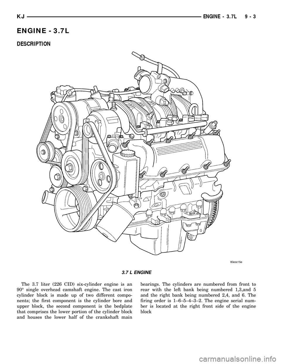
The 3.7 liter (226 CID) six-cylinder engine is an
90É single overhead camshaft engine. The cast iron
cylinder block is made up of two different compo-
nents; the first component is the cylinder bore and
upper block, the second component is the bedplate
that comprises the lower portion of the cylinder block
and houses the lower half of the crankshaft mainbearings. The cylinders are numbered from front to
rear with the left bank being numbered 1,3,and 5
and the right bank being numbered 2,4, and 6. The
firing order is 1±6±5±4±3±2. The engine serial num-
ber is located at the right front side of the engine
block
3.7 L ENGINE
KJENGINE - 3.7L 9 - 3
Page 1221 of 1803

DIAGNOSIS AND TESTING - ENGINE DIAGNOSIS - MECHANICAL
CONDITION POSSIBLE CAUSES CORRECTIONS
NOISY VALVES 1. High or low oil level in
crankcase.1. (Refer to LUBRICATION &
MAINTENANCE/FLUID TYPES -
SPECIFICATIONS).
2. Thin or diluted oil. 2. Change oil and filter.
3. Low oil pressure. 3. Check oil pump, if Ok, check rod
and main bearings for excessive
wear.
4. Dirt in lash adjusters. 4. Clean or replace as necessary.
5. Worn rocker arms. 5. Replace as necessary.
7. Worn valve guides. 7. (Refer to 9 - ENGINE/CYLINDER
HEAD/INTAKE/EXHAUST VALVES
& SEATS - STANDARD
PROCEDURE).
8. Excessive runout of valve seats
on valve faces.8. Service valves and valve seats.
(Refer to 9 - ENGINE/CYLINDER
HEAD/INTAKE/EXHAUST VALVES
& SEATS - STANDARD
PROCEDURE).
ENGINE VIBRATION 1. Counter Balance Shaft not timed
properly1. Refer to Engine Timing in this
section
CONNECTING ROD NOISE 1. Insufficient oil supply. 1. (Refer to LUBRICATION &
MAINTENANCE/FLUID TYPES -
SPECIFICATIONS).
2. Low oil pressure. 2. Check oil pump, if Ok, check rod
and main bearings for excessive
wear.
3. Thin or diluted oil. 3. Change oil and filter.
4. Excessive bearing clearance. 4. Replace as necessary.
5. Connecting rod journal
out-of-round.5. Service or replace crankshaft.
6. Misaligned connecting rods. 6. Replace bent connecting rods.
MAIN BEARING NOISE 1. Insufficient oil supply. 1. (Refer to LUBRICATION &
MAINTENANCE/FLUID TYPES -
SPECIFICATIONS).
2. Low oil pressure. 2. Check oil pump, if Ok, check rod
and main bearings for excessive
wear.
3. Thin or diluted oil. 3. Change oil and filter.
4. Excessive bearing clearance. 4. Replace as necessary.
5. Excessive end play. 5. Check thrust washers for wear.
6. Crankshaft journal out-of round. 6. Service or replace crankshaft.
7. Loose flywheel or torque
converter.7. Tighten to correct torque
9 - 6 ENGINE - 3.7LKJ
ENGINE - 3.7L (Continued)