2002 JEEP LIBERTY Front oil seal
[x] Cancel search: Front oil sealPage 207 of 1803

Common causes of runout are:
²heat warpage
²improper machining
²incorrect bolt tightening
²improper seating on crankshaft flange shoulder
²foreign material on crankshaft flange
Flywheel machining is not recommended. The fly-
wheel clutch surface is machined to a unique contour
and machining will negate this feature. Minor fly-
wheel scoring can be cleaned up by hand with 180
grit emery or with surface grinding equipment.
Remove only enough material to reduce scoring
(approximately 0.001 - 0.003 in.). Heavy stock
removal isnot recommended.Replace the flywheel
if scoring is severe and deeper than 0.076 mm (0.003
in.). Excessive stock removal can result in flywheel
cracking or warpage after installation; it can alsoweaken the flywheel and interfere with proper clutch
release.
Clean the crankshaft flange before mounting the
flywheel. Dirt and grease on the flange surface may
cock the flywheel causing excessive runout. Use new
bolts when remounting a flywheel and secure the
bolts with Mopar Lock And Seal or equivalent.
Tighten flywheel bolts to specified torque only. Over-
tightening can distort the flywheel hub causing
runout.
DIAGNOSIS CHART
The diagnosis charts Diagnosis Chart describe
common clutch problems, causes and correction. Con-
ditions, causes and corrective action are outlined in
the indicated columns.
DIAGNOSIS CHART
CONDITION POSSIBLE CAUSES CORRECTION
Disc facing worn out 1. Normal wear. 1. Replace cover and disc.
2. Driver frequently rides (slips) the
clutch. Results in rapid overheating
and wear.2. Replace cover and disc.
3. Insufficient clutch cover
diaphragm spring tension.3. Replace cover and disc.
Clutch disc facing contaminated with
oil, grease, or clutch fluid.1. Leak at rear main engine seal or
transmission input shaft seal.1. Replace appropriate seal.
2. Excessive amount of grease
applied to the input shaft splines.2. Remove grease and apply the
correct amount of grease.
3. Road splash, water entering
housing.3. Replace clutch disc. Clean clutch
cover and reuse if in good condition.
4. Slave cylinder leaking. 4. Replace hydraulic clutch linkage.
Clutch is running partially
disengaged.1. Release bearing sticking or
binding and does not return to the
normal running position.1. Verify failure. Replace the release
bearing and transmission front
bearing retainer as necessary.
Flywheel below minimum thickness
specification.1. Improper flywheel machining.
Flywheel has excessive taper or
excessive material removal.1. Replace flywheel.
Clutch disc, cover and/or diaphragm
spring warped or distorted.1. Rough handling. Impact bent
cover, spring, or disc.1. Replace disc or cover as
necessary.
2. Improper bolt tightening
procedure.2. Tighten clutch cover using proper
procedure.
KJCLUTCH 6 - 3
CLUTCH (Continued)
Page 320 of 1803

Schedule Condition Expected Operation
OverheatOil temperature above 240É F or
engine coolant temperature above
244É F- Delayed 2-3 upshift
- Delayed 3-4 upshift
- 3rd gear FEMCC from 30-48 mph
- 3rd gear PEMCC above 35 mph
- Above 25 mph the torque
converter will not unlock unless the
throttle is closed or if a wide open
throttle 2nd PEMCC to 1 kickdown
is made
STANDARD PROCEDURE - TCM QUICK LEARN
The quick learn procedure requires the use of the
DRBtscan tool.
This program allows the electronic transmission
system to recalibrate itself. This will provide the
proper transmission operation. The quick learn pro-
cedure should be performed if any of the following
procedures are performed:
²Transmission Assembly Replacement
²Transmission Control Module Replacement
²Solenoid Pack Replacement
²Clutch Plate and/or Seal Replacement
²Valve Body Replacement or Recondition
To perform the Quick Learn Procedure, the follow-
ing conditions must be met:
²The brakes must be applied
²The engine speed must be above 500 rpm
²The throttle angle (TPS) must be less than 3
degrees
²The shift lever position must stay in PARK until
prompted to shift to overdrive
²The shift lever position must stay in overdrive
after the Shift to Overdrive prompt until the DRBt
indicates the procedure is complete
²The calculated oil temperature must be above
60É and below 200É
HEATED SEAT MODULE
DESCRIPTION
The heated seat module is also known as the Seat
Heat Interface Module. The heated seat module (Fig.
14) is located under the left front seat cushion, where
it is secured to a mounting bracket via two push-pin
retainers. The heated seat module has a single con-
nector receptacle that allows the module to be con-
nected to all of the required inputs and outputs
through the seat wire harness.
The heated seat module is an electronic micropro-
cessor controlled device designed and programmed to
use inputs from the heated seat relay, the two heatedseat switches and the two heated seat sensors to
operate and control the heated seat elements in both
front seats and the two heated seat indicator lamp
Light-Emitting Diodes (LEDs) in each heated seat
switch. The heated seat module is also programmed
to perform self-diagnosis of certain heated seat sys-
tem functions and provide feedback of that diagnosis
through the heated seat switch indicator lamps.
The heated seat module cannot be repaired. If the
heated seat module is damaged or faulty, the entire
module must be replaced.
OPERATION
The heated seat module operates on fused battery
current received from a fuse in the junction block.
The module is grounded at all times. Inputs to the
module include a resistor multiplexed heated seat
switch request circuit for each of the two heated seat
switches and the heated seat sensor inputs from the
seat cushions of each front seat. In response to those
inputs, the heated seat module controls battery cur-
rent to the heated seat elements and sensors, and
Fig. 14 Heated Seat Module
1 - Mounting Tabs (Not Used On KJ)
2 - Heated Seat Module
3 - Connector Receptacle
KJELECTRONIC CONTROL MODULES 8E - 21
TRANSMISSION CONTROL MODULE (Continued)
Page 472 of 1803

HEADLAMP BULB
REMOVAL
NORTH AMERICA
(1) Disconnect and isolate the battery negative
cable.
(2) Reach behind the headlamp unit from the
engine compartment side of the upper radiator cross-
member to access the headlamp bulb lock ring (Fig.
23).
(3) Firmly grasp the lock ring on the back of the
headlamp unit housing.
(4) Rotate the lock ring on the back of the head-
lamp unit housing counterclockwise about 30
degrees.
CAUTION: Do not contaminate the bulb glass by
touching it with your fingers or by allowing it to
contact other oily surfaces. Shortened bulb life will
result.
(5) Pull the lock ring, socket, and bulb straight out
of the headlamp unit housing and up from behind
the upper radiator crossmember (Fig. 24).
(6) Disconnect the grille opening reinforcement
wire harness connector for the headlamp bulb from
the connector receptacle on the bulb socket.
(7) Remove the bulb and bulb socket from the lock
ring as a unit.
REST-OF-WORLD
(1) Disconnect and isolate the battery negative
cable.(2) Remove the headlamp unit from the grille
opening reinforcement. (Refer to 8 - ELECTRICAL/
LAMPS/LIGHTING - EXTERIOR/HEADLAMP UNIT
- REMOVAL).
(3) Firmly grasp the tab of the headlamp boot seal
on the back of the headlamp unit housing (Fig. 25).
(4) Pull the tab away from the back of the head-
lamp unit housing to remove the boot seal from the
housing and the bulb base.
Fig. 23 Headlamp Bulb Lock Ring
1 - HEADLAMP UNIT HOUSING
2 - LOCK RING
3 - SOCKET & BULB
Fig. 24 Headlamp Bulb Remove/Install
1 - HEADLAMP BULB
2 - SOCKET
3 - LOCK RING
Fig. 25 Headlamp Bulb Boot Seal Remove
1 - LEVELING MOTOR (IF EQUIPPED)
2 - BOOT SEAL
3 - FRONT POSITION LAMP
4 - ADJUSTING SCREW
5-TAB
6 - BULB BASE
KJLAMPS/LIGHTING - EXTERIOR 8L - 31
Page 556 of 1803
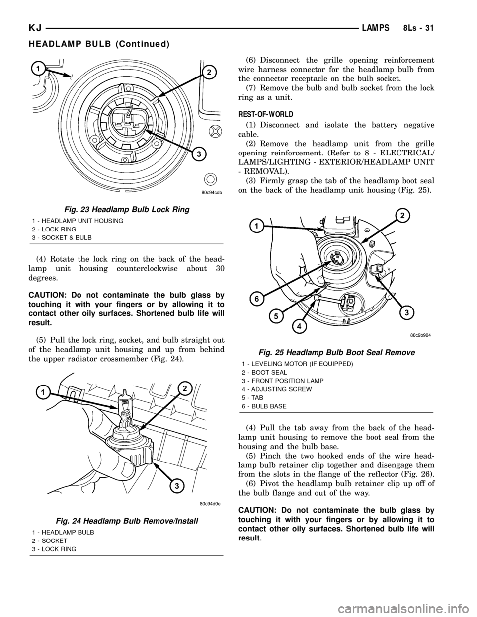
(4) Rotate the lock ring on the back of the head-
lamp unit housing counterclockwise about 30
degrees.
CAUTION: Do not contaminate the bulb glass by
touching it with your fingers or by allowing it to
contact other oily surfaces. Shortened bulb life will
result.
(5) Pull the lock ring, socket, and bulb straight out
of the headlamp unit housing and up from behind
the upper radiator crossmember (Fig. 24).(6) Disconnect the grille opening reinforcement
wire harness connector for the headlamp bulb from
the connector receptacle on the bulb socket.
(7) Remove the bulb and bulb socket from the lock
ring as a unit.
REST-OF-WORLD
(1) Disconnect and isolate the battery negative
cable.
(2) Remove the headlamp unit from the grille
opening reinforcement. (Refer to 8 - ELECTRICAL/
LAMPS/LIGHTING - EXTERIOR/HEADLAMP UNIT
- REMOVAL).
(3) Firmly grasp the tab of the headlamp boot seal
on the back of the headlamp unit housing (Fig. 25).
(4) Pull the tab away from the back of the head-
lamp unit housing to remove the boot seal from the
housing and the bulb base.
(5) Pinch the two hooked ends of the wire head-
lamp bulb retainer clip together and disengage them
from the slots in the flange of the reflector (Fig. 26).
(6) Pivot the headlamp bulb retainer clip up off of
the bulb flange and out of the way.
CAUTION: Do not contaminate the bulb glass by
touching it with your fingers or by allowing it to
contact other oily surfaces. Shortened bulb life will
result.
Fig. 23 Headlamp Bulb Lock Ring
1 - HEADLAMP UNIT HOUSING
2 - LOCK RING
3 - SOCKET & BULB
Fig. 24 Headlamp Bulb Remove/Install
1 - HEADLAMP BULB
2 - SOCKET
3 - LOCK RING
Fig. 25 Headlamp Bulb Boot Seal Remove
1 - LEVELING MOTOR (IF EQUIPPED)
2 - BOOT SEAL
3 - FRONT POSITION LAMP
4 - ADJUSTING SCREW
5-TAB
6 - BULB BASE
KJLAMPS8Ls-31
HEADLAMP BULB (Continued)
Page 1217 of 1803
ENGINE BLOCK
DESCRIPTION.........................39
STANDARD PROCEDURE - CYLINDER BORE
HONING............................39
CLEANING............................39
INSPECTION..........................40
CONNECTING ROD BEARINGS
STANDARD PROCEDURE - CONNECTING
ROD BEARING - FITTING...............40
CRANKSHAFT
DESCRIPTION.........................42
REMOVAL.............................43
INSPECTION..........................43
INSTALLATION.........................43
CRANKSHAFT MAIN BEARINGS
STANDARD PROCEDURE
MAIN BEARING - FITTING...............45
CRANKSHAFT OIL SEAL - FRONT
REMOVAL.............................46
INSTALLATION.........................47
CRANKSHAFT OIL SEAL - REAR
REMOVAL.............................48
INSTALLATION.........................48
FLEX PLATE
REMOVAL.............................49
INSTALLATION.........................49
PISTON & CONNECTING ROD
DESCRIPTION.........................49
STANDARD PROCEDURE
CONNECTING ROD BEARING - FITTING . . . 49
STANDARD PROCEDURE - PISTON
FITTING.............................50
REMOVAL.............................50
CLEANING............................51
INSPECTION..........................51
INSTALLATION.........................51
PISTON RINGS
STANDARD PROCEDURE - PISTON RING
FITTING.............................52
VIBRATION DAMPER
REMOVAL.............................54
INSTALLATION.........................55
STRUCTURAL COVER
DESCRIPTION.........................55
OPERATION...........................55
REMOVAL.............................55
INSTALLATION.........................55
FRONT MOUNT
REMOVAL.............................56
INSTALLATION.........................57
REAR MOUNT
REMOVAL.............................57
INSTALLATION.........................57
LUBRICATION
DESCRIPTION.........................57
OPERATION...........................58DIAGNOSIS AND TESTING
DIAGNOSIS AND TESTING - ENGINE OIL
LEAK...............................60
DIAGNOSIS AND TESTING - ENGINE OIL
PRESSURE..........................60
DIAGNOSIS AND TESTING - REAR SEAL
AREA LEAKS.........................61
OIL
STANDARD PROCEDURE - ENGINE OIL.....61
OIL FILTER
REMOVAL.............................63
INSTALLATION.........................63
OIL PAN
DESCRIPTION.........................63
REMOVAL.............................63
CLEANING............................63
INSPECTION..........................63
INSTALLATION.........................64
OIL PRESSURE SENSOR/SWITCH
DESCRIPTION.........................65
OPERATION...........................65
REMOVAL.............................65
INSTALLATION.........................65
OIL PUMP
REMOVAL.............................65
DISASSEMBLY.........................65
INSPECTION..........................66
ASSEMBLY............................67
INSTALLATION.........................67
INTAKE MANIFOLD
DESCRIPTION.........................68
DIAGNOSIS AND TESTING - INTAKE
MANIFOLD LEAKS.....................68
REMOVAL.............................68
INSTALLATION.........................69
EXHAUST MANIFOLD
DESCRIPTION.........................69
REMOVAL.............................69
INSTALLATION.........................70
VALVE TIMING
DESCRIPTION.........................71
OPERATION...........................71
STANDARD PROCEDURE
MEASURING TIMING CHAIN WEAR.......71
SERVICE PROCEDURES...............72
BALANCE SHAFT
REMOVAL.............................74
INSTALLATION.........................74
TIMING BELT / CHAIN COVER(S)
REMOVAL.............................74
INSTALLATION.........................76
IDLER SHAFT
REMOVAL.............................77
INSTALLATION.........................77
TIMING BELT/CHAIN AND SPROCKET(S
REMOVAL.............................77
INSPECTION..........................79
INSTALLATION.........................80
9 - 2 ENGINE - 3.7LKJ
Page 1230 of 1803
DESCRIPTION SPECIFICATION
Cylinder Head Warpage
(Flatness) 0.0508 mm (0.002 in.)
OIL PUMP
Clearance Over
Rotors/End Face(MAX)0.035 - 0.095 mm
(0.0014 - 0.0038 in.)
Cover Out - of -Flat
(MAX)0.025 mm (0.001 in.)
Inner and Outer Rotor
Thickness 12.02 mm (0.4731 in.)
Outer Rotor Diameter
(MAX).235 mm (.0093 in.)
Outer Rotor Diameter
(MIN)85.925 mm (0.400 in.)
Tip Clearance Between
Rotors
(MAX) 0.150 mm (0.006 in.)
OIL PRESSURE
At Curb Idle Speed
(MIN)*25 kPa (4 psi)
@ 3000 rpm 170 - 758 kPa (25 - 110
psi)
* CAUTION: If pressure is zero at curb idle, DO
NOT run engine at 3000 rpm.
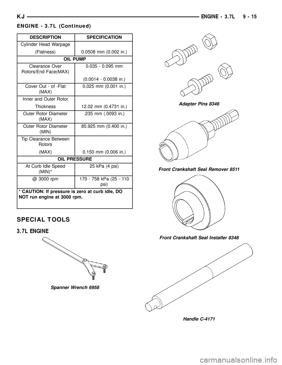
SPECIAL TOOLS
3.7L ENGINE
Spanner Wrench 6958
Adapter Pins 8346
Front Crankshaft Seal Remover 8511
Front Crankshaft Seal Installer 8348
Handle C-4171
KJENGINE - 3.7L 9 - 15
ENGINE - 3.7L (Continued)
Page 1243 of 1803
TESTING VALVE SPRINGS
NOTE: Whenever the valves are removed from the
cylinder head it is recommended that the valve
springs be inspected and tested for reuse.
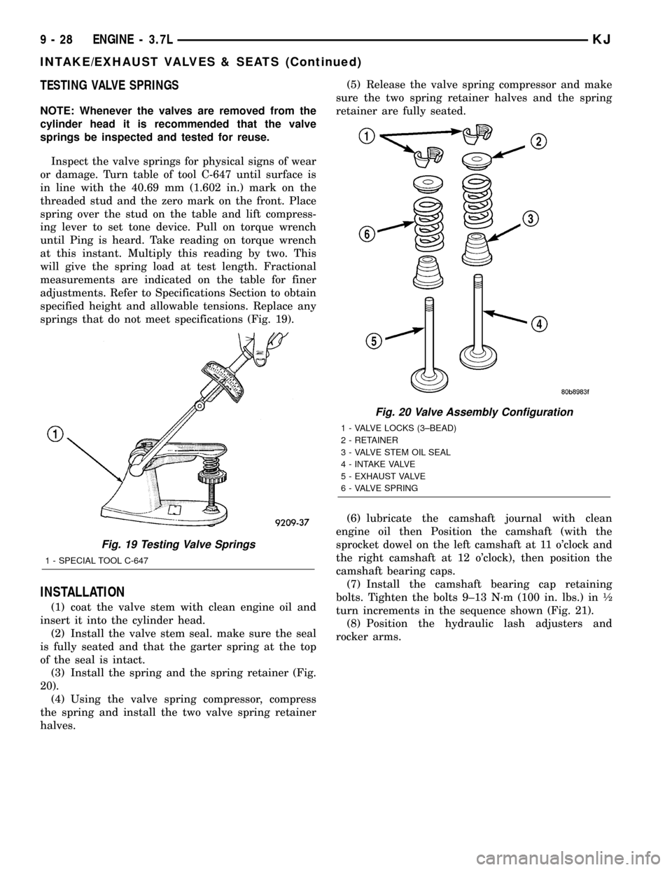
Inspect the valve springs for physical signs of wear
or damage. Turn table of tool C-647 until surface is
in line with the 40.69 mm (1.602 in.) mark on the
threaded stud and the zero mark on the front. Place
spring over the stud on the table and lift compress-
ing lever to set tone device. Pull on torque wrench
until Ping is heard. Take reading on torque wrench
at this instant. Multiply this reading by two. This
will give the spring load at test length. Fractional
measurements are indicated on the table for finer
adjustments. Refer to Specifications Section to obtain
specified height and allowable tensions. Replace any
springs that do not meet specifications (Fig. 19).
INSTALLATION
(1) coat the valve stem with clean engine oil and
insert it into the cylinder head.
(2) Install the valve stem seal. make sure the seal
is fully seated and that the garter spring at the top
of the seal is intact.
(3) Install the spring and the spring retainer (Fig.
20).
(4) Using the valve spring compressor, compress
the spring and install the two valve spring retainer
halves.(5) Release the valve spring compressor and make
sure the two spring retainer halves and the spring
retainer are fully seated.
(6) lubricate the camshaft journal with clean
engine oil then Position the camshaft (with the
sprocket dowel on the left camshaft at 11 o'clock and
the right camshaft at 12 o'clock), then position the
camshaft bearing caps.
(7) Install the camshaft bearing cap retaining
bolts. Tighten the bolts 9±13 N´m (100 in. lbs.) in ó
turn increments in the sequence shown (Fig. 21).
(8) Position the hydraulic lash adjusters and
rocker arms.
Fig. 19 Testing Valve Springs
1 - SPECIAL TOOL C-647
Fig. 20 Valve Assembly Configuration
1 - VALVE LOCKS (3±BEAD)
2 - RETAINER
3 - VALVE STEM OIL SEAL
4 - INTAKE VALVE
5 - EXHAUST VALVE
6 - VALVE SPRING
9 - 28 ENGINE - 3.7LKJ
INTAKE/EXHAUST VALVES & SEATS (Continued)
Page 1246 of 1803
VISUAL TEST METHOD
With the engine cool, remove the coolant pressure
cap. Start the engine and allow it to warm up until
thermostat opens.
If a large combustion/compression pressure leak
exists, bubbles will be visible in the coolant.
COOLING SYSTEM TESTER METHOD
WARNING: WITH COOLING SYSTEM TESTER IN
PLACE, PRESSURE WILL BUILD UP FAST. EXCES-
SIVE PRESSURE BUILT UP, BY CONTINUOUS
ENGINE OPERATION, MUST BE RELEASED TO A
SAFE PRESSURE POINT. NEVER PERMIT PRES-
SURE TO EXCEED 138 kPa (20 psi).
Install Cooling System Tester 7700 or equivalent to
pressure cap neck. Start the engine and observe the
tester's pressure gauge. If gauge pulsates with every
power stroke of a cylinder a combustion pressure
leak is evident.
CHEMICAL TEST METHOD
Combustion leaks into the cooling system can also
be checked by using Bloc-Chek Kit C-3685-A or
equivalent. Perform test following the procedures
supplied with the tool kit.
REMOVAL
(1) Disconnect battery negative cable.
(2) Raise the vehicle on a hoist.
(3) Disconnect the exhaust pipe at the right side
exhaust manifold.
(4) Drain the engine coolant. Refer to COOLING
SYSTEM.
(5) Lower the vehicle.
(6) Remove the intake manifold. Refer to proce-
dure.
(7) Remove the cylinder head cover. Refer to proce-
dure.
(8) Remove the fan shroud. Refer to COOLING
SYSTEM.
(9) Remove oil fill housing from cylinder head.
(10) Remove accessory drive belt. Refer to COOL-
ING SYSTEM.
(11) Rotate the crankshaft until the damper timing
mark is aligned with TDC indicator mark.
(12) Verify the V6 mark on the camshaft sprocket
is at the 12 o'clock position. Rotate the crankshaft
one turn if necessary.
(13) Remove the crankshaft damper. Refer to pro-
cedure.
(14) Remove the timing chain cover. Refer to pro-
cedure.
(15) Lock the secondary timing chains to the idler
sprocket using Special Tool 8429 Timing Chain Hold-
ing Fixture.NOTE: Mark the secondary timing chain prior to
removal to aid in installation.
(16) Mark the secondary timing chain, one link on
each side of the V6 mark on the camshaft drive gear.
(17) Remove the right side secondary chain ten-
sioner. Refer to Timing Chain and Sprockets in this
section.
(18) Remove the cylinder head access plug.
(19) Remove the right side secondary chain guide.
Refer to Timing Chain and Sprockets in this section.
CAUTION: The nut on the right side camshaft
sprocket should not be removed for any reason, as
the sprocket and camshaft sensor target wheel is
serviced as an assembly. If the nut was removed
retorque nut to 5 N´m (44 in. lbs.).
(20) Remove the retaining bolt and the camshaft
drive gear.
CAUTION: Do not allow the engine to rotate. severe
damage to the valve train can occur.
CAUTION: Do not overlook the four smaller bolts at
the front of the cylinder head. Do not attempt to
remove the cylinder head without removing these
four bolts.
CAUTION: Do not hold or pry on the camshaft tar-
get wheel for any reason. A damaged target wheel
can result in a vehicle no start condition.
NOTE: The cylinder head is attached to the cylinder
block with twelve bolts.
(21) Remove the cylinder head retaining bolts.
(22) Remove the cylinder head and gasket. Discard
the gasket.
CAUTION: Do not lay the cylinder head on its gas-
ket sealing surface, do to the design of the cylinder
head gasket any distortion to the cylinder head
sealing surface may prevent the gasket from prop-
erly sealing resulting in leaks.
CLEANING
To ensure engine gasket sealing, proper surface
preparation must be performed, especially with the
use of aluminum engine components (Fig. 22). (Refer
to 9 - ENGINE - STANDARD PROCEDURE)
KJENGINE - 3.7L 9 - 31
CYLINDER HEAD - RIGHT (Continued)