2002 JEEP LIBERTY engine block
[x] Cancel search: engine blockPage 1313 of 1803
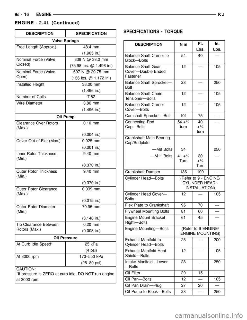
DESCRIPTION SPECIFICATION
Valve Springs
Free Length (Approx.) 48.4 mm
(1.905 in.)
Nominal Force (Valve
Closed)338 N @ 38.0 mm
(75.98 lbs. @ 1.496 in.)
Nominal Force (Valve
Open)607 N @ 29.75 mm
(136 lbs. @ 1.172 in.)
Installed Height 38.00 mm
(1.496 in.)
Number of Coils 7.82
Wire Diameter 3.86 mm
(1.496 in.)
Oil Pump
Clearance Over Rotors
(Max.)0.10 mm
(0.004 in.)
Cover Out-of-Flat (Max.) 0.025 mm
(0.001 in.)
Inner Rotor Thickness
(Min.)9.40 mm
(0.370 in.)
Outer Rotor Thickness
(Min.)9.40 mm
(0.370 in.)
Outer Rotor Clearance
(Max.)0.039 mm
(0.015 in.)
Outer Rotor Diameter
(Min.)79.95 mm
(3.148 in.)
Tip Clearance Between
Rotors (Max.)0.20 mm
(0.008 in.)
Oil Pressure
At Curb Idle Speed* 25 kPa
(4 psi)
At 3000 rpm 170±550 kPa
(25±80 psi)
CAUTION:
*If pressure is ZERO at curb idle, DO NOT run engine
at 3000 rpm.SPECIFICATIONS - TORQUE
DESCRIPTION N´mFt.
Lbs.In.
Lbs.
Balance Shaft Carrier to
BlockÐBolts54 40 Ð
Balance Shaft Gear
CoverÐDouble Ended
Fastener12 Ð 105
Balance Shaft SprocketÐ
Bolt28 Ð 250
Balance Shaft Chain
TensionerÐBolts12 Ð 105
Balance Shaft Carrier
CoverÐBolts12 Ð 105
Camshaft SprocketÐBolt 101 75 Ð
Connecting Rod
CapÐBolts54 +
1¤4
turn40
+1¤4
turnÐ
Crankshaft Main Bearing
Cap/Bedplate
ÐM8 Bolts 34 250
ÐM11 Bolts 41 +
1¤4
Turn30
+1¤4
TurnÐ
Crankshaft Damper 136 100 Ð
Cylinder HeadÐBolts (Refer to 9 - ENGINE/
CYLINDER HEAD -
INSTALLATION)
Cylinder Head CoverÐ
Bolts12 Ð 105
Flex Plate to Crankshaft 95 70 Ð
Flywheel Mounting Bolts 81 60 Ð
Engine Mount Bracket
RightÐBolts61 45 Ð
Engine MountingÐBolts (Refer to 9 ENGINE/
ENGINE MOUNTING)
Exhaust Manifold to
Cylinder HeadÐBolts23 Ð 200
Exhaust Manifold Heat
ShieldÐBolts12 Ð 105
Intake Manifold - Lower
ÐBolts28 Ð 250
Oil Filter 20 15 Ð
Oil PanÐBolts 12 Ð 105
Oil Pan DrainÐPlug 27 20 Ð
Oil Pump to BlockÐBolts 28 Ð 250
9s - 16 ENGINEKJ
ENGINE - 2.4L (Continued)
Page 1316 of 1803
AIR CLEANER ELEMENT
REMOVAL - 2.4L
Housing removal is not necessary for element (fil-
ter) replacement.
(1) Disconnect air intake duct at side of element
cover.
(2) Pry up 2 spring clips from front of housing
cover (spring clips retain cover to housing).
(3) Release housing cover from locating tabs
located on rear of housing, and remove cover.
(4) Remove air cleaner element (filter) from hous-
ing.
(5) Clean inside of housing before replacing ele-
ment.
INSTALLATION - 2.4L
(1) Install element into housing.
(2) Position housing cover into housing locating
tabs.
(3) Pry up spring clips and lock cover to housing.
(4) Connect air intake duct.
If any air filter, air resonator, air intake tubes or
air filter housing clamps had been loosened or
removed, tighten them to 5 N´m (40 in. lbs.) torque.
CYLINDER HEAD
DESCRIPTION
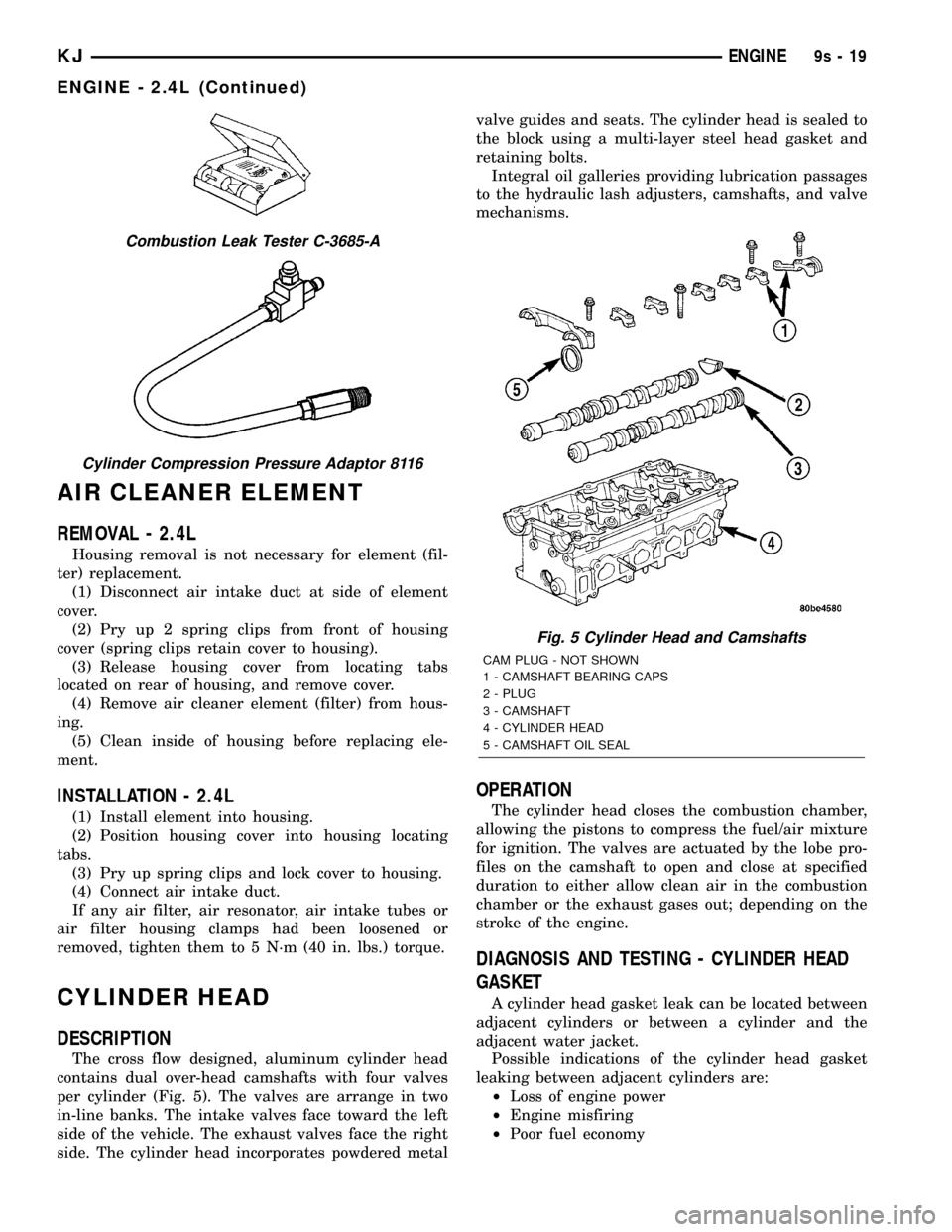
The cross flow designed, aluminum cylinder head
contains dual over-head camshafts with four valves
per cylinder (Fig. 5). The valves are arrange in two
in-line banks. The intake valves face toward the left
side of the vehicle. The exhaust valves face the right
side. The cylinder head incorporates powdered metalvalve guides and seats. The cylinder head is sealed to
the block using a multi-layer steel head gasket and
retaining bolts.
Integral oil galleries providing lubrication passages
to the hydraulic lash adjusters, camshafts, and valve
mechanisms.
OPERATION
The cylinder head closes the combustion chamber,
allowing the pistons to compress the fuel/air mixture
for ignition. The valves are actuated by the lobe pro-
files on the camshaft to open and close at specified
duration to either allow clean air in the combustion
chamber or the exhaust gases out; depending on the
stroke of the engine.
DIAGNOSIS AND TESTING - CYLINDER HEAD
GASKET
A cylinder head gasket leak can be located between
adjacent cylinders or between a cylinder and the
adjacent water jacket.
Possible indications of the cylinder head gasket
leaking between adjacent cylinders are:
²Loss of engine power
²Engine misfiring
²Poor fuel economy
Combustion Leak Tester C-3685-A
Cylinder Compression Pressure Adaptor 8116
Fig. 5 Cylinder Head and Camshafts
CAM PLUG - NOT SHOWN
1 - CAMSHAFT BEARING CAPS
2 - PLUG
3 - CAMSHAFT
4 - CYLINDER HEAD
5 - CAMSHAFT OIL SEAL
KJENGINE9s-19
ENGINE - 2.4L (Continued)
Page 1317 of 1803
Possible indications of the cylinder head gasket
leaking between a cylinder and an adjacent water
jacket are:
²Engine overheating
²Loss of coolant
²Excessive steam (white smoke) emitting from
exhaust
²Coolant foaming
CYLINDER-TO-CYLINDER LEAKAGE TEST
To determine if an engine cylinder head gasket is
leaking between adjacent cylinders, follow the proce-
dures in Cylinder Compression Pressure Test (Refer
to 9 - ENGINE - DIAGNOSIS AND TESTING). An
engine cylinder head gasket leaking between adja-
cent cylinders will result in approximately a 50±70%
reduction in compression pressure.
CYLINDER-TO-WATER JACKET LEAKAGE TEST
WARNING: USE EXTREME CAUTION WHEN THE
ENGINE IS OPERATING WITH COOLANT PRES-
SURE CAP REMOVED.
VISUAL TEST METHOD
With the engine cool, remove the coolant pressure
cap. Start the engine and allow it to warm up until
thermostat opens.
If a large combustion/compression pressure leak
exists, bubbles will be visible in the coolant.
COOLING SYSTEM TESTER METHOD
WARNING: WITH COOLING SYSTEM TESTER IN
PLACE, PRESSURE WILL BUILD UP FAST. EXCES-
SIVE PRESSURE BUILT UP, BY CONTINUOUS
ENGINE OPERATION, MUST BE RELEASED TO A
SAFE PRESSURE POINT. NEVER PERMIT PRES-
SURE TO EXCEED 138 kPa (20 psi).
Install Cooling System Tester 7700 or equivalent to
pressure cap neck. Start the engine and observe the
tester's pressure gauge. If gauge pulsates with every
power stroke of a cylinder a combustion pressure
leak is evident.
CHEMICAL TEST METHOD
Combustion leaks into the cooling system can also
be checked by using Bloc-Chek Kit C-3685-A or
equivalent. Perform test following the procedures
supplied with the tool kit.
REMOVAL - CYLINDER HEAD
(1) Perform fuel system pressure release procedure
before attempting any repairs.(Refer to 14 -FUEL SYSTEM/FUEL DELIVERY - SPECIFICA-
TIONS)
(2) Disconnect battery negative cable.
(3) Drain cooling system. (Refer to 7 - COOLING -
STANDARD PROCEDURE)
(4) Remove air filter housing and inlet tube.
(5) Remove intake manifold.
(6) Remove heater tube support bracket from cyl-
inder head.
(7) Disconnect radiator upper and heater supply
hoses from water outlet connections.
(8) Remove accessory drive belts. (Refer to 7 -
COOLING/ACCESSORY DRIVE/DRIVE BELTS -
REMOVAL)
(9) Raise vehicle and remove exhaust pipe from
manifold.
(10) Remove power steering pump and set aside.
Do not disconnect lines.
(11) Remove accessory drive bracket
(12) Remove ignition coil and wires from engine.
(13) Disconnect cam sensor and fuel injector wir-
ing connectors.
(14) Remove timing belt and camshaft sprockets.
(Refer to 9 - ENGINE/VALVE TIMING/TIMING
BELT/CHAIN AND SPROCKETS - REMOVAL)
(15) Remove timing belt idler pulley and rear tim-
ing belt cover. (Refer to 9 - ENGINE/VALVE TIM-
ING/TIMING BELT / CHAIN COVER(S) -
REMOVAL)
(16) Remove cylinder head cover. (Refer to 9 -
ENGINE/CYLINDER HEAD/CYLINDER HEAD
COVER(S) - REMOVAL)
(17) Remove camshafts (Refer to 9 - ENGINE/
CYLINDER HEAD/CAMSHAFT(S) - REMOVAL).
NOTE: Identify rocker arm position to ensure cor-
rect re-installation in original position, if reused.
(18) Remove rocker arms. (Refer to 9 - ENGINE/
CYLINDER HEAD/ROCKER ARMS - REMOVAL).
(19) Remove cylinder head bolts in REVERSE
sequence of tightening.
(20) Remove cylinder head from engine block.
(21) Inspect and clean cylinder head. (Refer to 9 -
ENGINE/CYLINDER HEAD - INSPECTION) (Refer
to 9 - ENGINE/CYLINDER HEAD - CLEANING)
CLEANING
To ensure engine gasket sealing, proper surface
preparation must be performed, especially with the
use of aluminum engine components and multi-layer
steel cylinder head gaskets.
NOTE: Multi-Layer Steel (MLS) head gaskets require
a scratch free sealing surface.
9s - 20 ENGINEKJ
CYLINDER HEAD (Continued)
Page 1318 of 1803
Remove all gasket material from cylinder head and
block (Refer to 9 - ENGINE - STANDARD PROCE-
DURE). Be careful not to gouge or scratch the alumi-
num head sealing surface.
Clean all engine oil passages.
INSPECTION
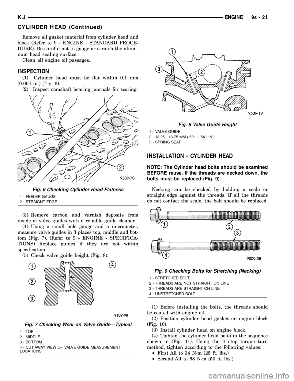
(1) Cylinder head must be flat within 0.1 mm
(0.004 in.) (Fig. 6).
(2) Inspect camshaft bearing journals for scoring.
(3) Remove carbon and varnish deposits from
inside of valve guides with a reliable guide cleaner.
(4) Using a small hole gauge and a micrometer,
measure valve guides in 3 places top, middle and bot-
tom (Fig. 7). (Refer to 9 - ENGINE - SPECIFICA-
TIONS) Replace guides if they are not within
specification.
(5) Check valve guide height (Fig. 8).
INSTALLATION - CYLINDER HEAD
NOTE: The Cylinder head bolts should be examined
BEFORE reuse. If the threads are necked down, the
bolts must be replaced (Fig. 9).
Necking can be checked by holding a scale or
straight edge against the threads. If all the threads
do not contact the scale, the bolt should be replaced.
(1) Before installing the bolts, the threads should
be coated with engine oil.
(2) Position cylinder head gasket on engine block
(Fig. 10).
(3) Install cylinder head on engine block.
(4) Tighten the cylinder head bolts in the sequence
shown in (Fig. 11). Using the 4 step torque turn
method, tighten according to the following values:
²First All to 34 N´m (25 ft. lbs.)
²Second All to 68 N´m (50 ft. lbs.)
Fig. 6 Checking Cylinder Head Flatness
1 - FEELER GAUGE
2 - STRAIGHT EDGE
Fig. 7 Checking Wear on Valve GuideÐTypical
1-TOP
2 - MIDDLE
3 - BOTTOM
4 - CUT AWAY VIEW OF VALVE GUIDE MEASUREMENT
LOCATIONS
Fig. 8 Valve Guide Height
1 - VALVE GUIDE
2 - 13.25 - 13.75 MM (.521 - .541 IN.)
3 - SPRING SEAT
Fig. 9 Checking Bolts for Stretching (Necking)
1 - STRETCHED BOLT
2 - THREADS ARE NOT STRAIGHT ON LINE
3 - THREADS ARE STRAIGHT ON LINE
4 - UNSTRETCHED BOLT
KJENGINE9s-21
CYLINDER HEAD (Continued)
Page 1324 of 1803
(4) Install cylinder head cover assembly to cylin-
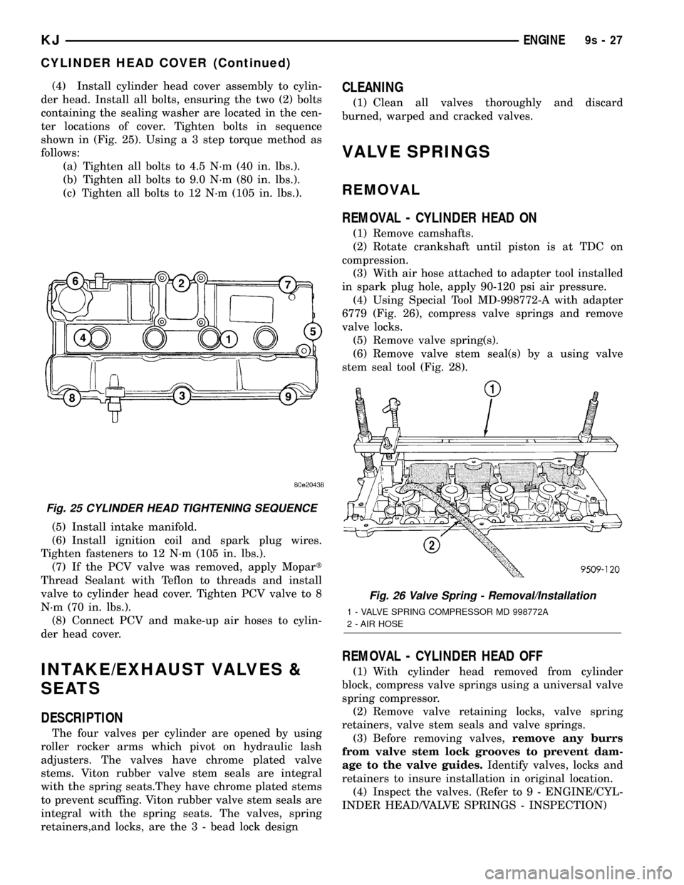
der head. Install all bolts, ensuring the two (2) bolts
containing the sealing washer are located in the cen-
ter locations of cover. Tighten bolts in sequence
shown in (Fig. 25). Using a 3 step torque method as
follows:
(a) Tighten all bolts to 4.5 N´m (40 in. lbs.).
(b) Tighten all bolts to 9.0 N´m (80 in. lbs.).
(c) Tighten all bolts to 12 N´m (105 in. lbs.).
(5) Install intake manifold.
(6) Install ignition coil and spark plug wires.
Tighten fasteners to 12 N´m (105 in. lbs.).
(7) If the PCV valve was removed, apply Mopart
Thread Sealant with Teflon to threads and install
valve to cylinder head cover. Tighten PCV valve to 8
N´m (70 in. lbs.).
(8) Connect PCV and make-up air hoses to cylin-
der head cover.
INTAKE/EXHAUST VALVES &
SEATS
DESCRIPTION
The four valves per cylinder are opened by using
roller rocker arms which pivot on hydraulic lash
adjusters. The valves have chrome plated valve
stems. Viton rubber valve stem seals are integral
with the spring seats.They have chrome plated stems
to prevent scuffing. Viton rubber valve stem seals are
integral with the spring seats. The valves, spring
retainers,and locks, are the 3 - bead lock design
CLEANING
(1) Clean all valves thoroughly and discard
burned, warped and cracked valves.
VALVE SPRINGS
REMOVAL
REMOVAL - CYLINDER HEAD ON
(1) Remove camshafts.
(2) Rotate crankshaft until piston is at TDC on
compression.
(3) With air hose attached to adapter tool installed
in spark plug hole, apply 90-120 psi air pressure.
(4) Using Special Tool MD-998772-A with adapter
6779 (Fig. 26), compress valve springs and remove
valve locks.
(5) Remove valve spring(s).
(6) Remove valve stem seal(s) by a using valve
stem seal tool (Fig. 28).
REMOVAL - CYLINDER HEAD OFF
(1) With cylinder head removed from cylinder
block, compress valve springs using a universal valve
spring compressor.
(2) Remove valve retaining locks, valve spring
retainers, valve stem seals and valve springs.
(3) Before removing valves,remove any burrs
from valve stem lock grooves to prevent dam-
age to the valve guides.Identify valves, locks and
retainers to insure installation in original location.
(4) Inspect the valves. (Refer to 9 - ENGINE/CYL-
INDER HEAD/VALVE SPRINGS - INSPECTION)
Fig. 25 CYLINDER HEAD TIGHTENING SEQUENCE
Fig. 26 Valve Spring - Removal/Installation
1 - VALVE SPRING COMPRESSOR MD 998772A
2 - AIR HOSE
KJENGINE9s-27
CYLINDER HEAD COVER (Continued)
Page 1327 of 1803
CAUTION: If cam follower assemblies are to be
reused, always mark position for reassembly in
their original positions.
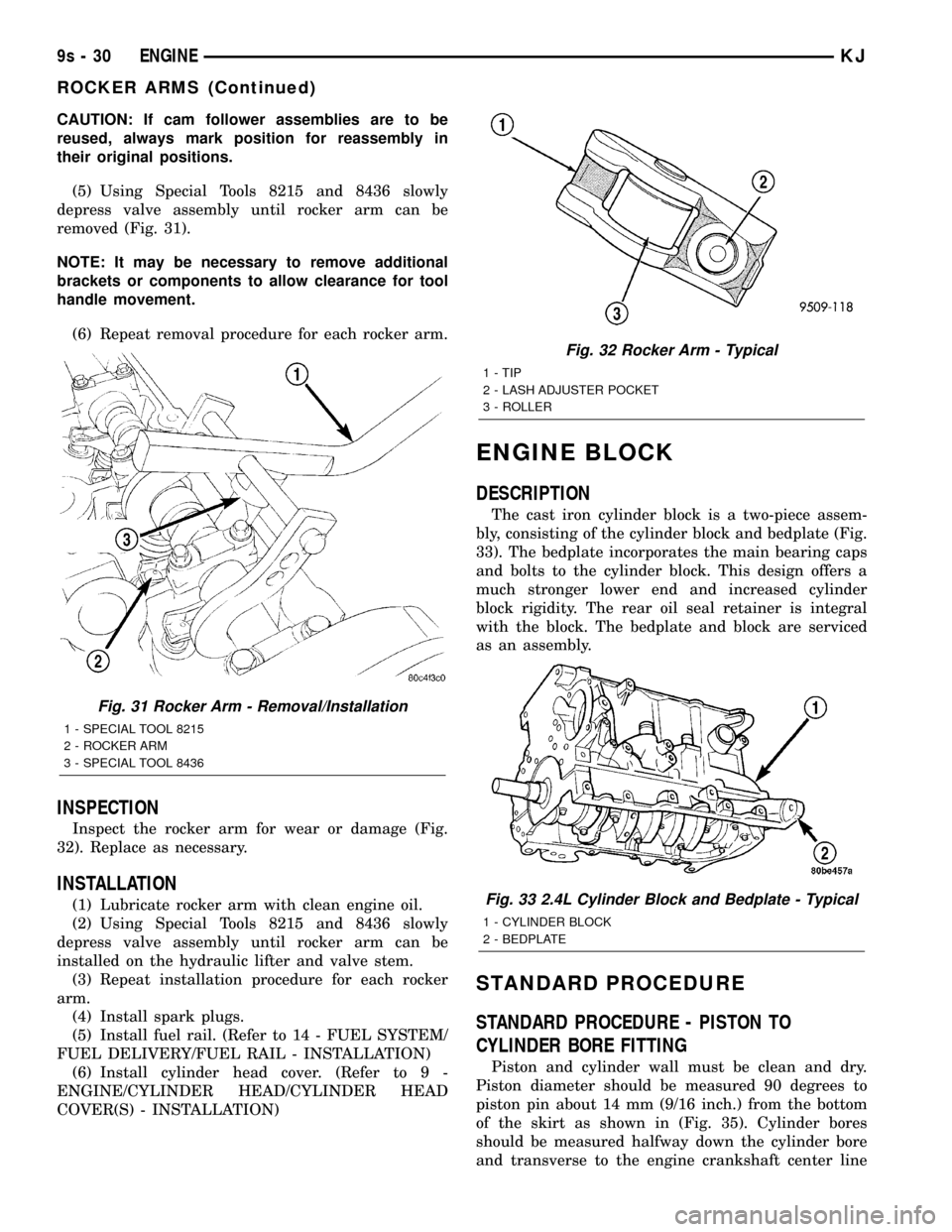
(5) Using Special Tools 8215 and 8436 slowly
depress valve assembly until rocker arm can be
removed (Fig. 31).
NOTE: It may be necessary to remove additional
brackets or components to allow clearance for tool
handle movement.
(6) Repeat removal procedure for each rocker arm.
INSPECTION
Inspect the rocker arm for wear or damage (Fig.
32). Replace as necessary.
INSTALLATION
(1) Lubricate rocker arm with clean engine oil.
(2) Using Special Tools 8215 and 8436 slowly
depress valve assembly until rocker arm can be
installed on the hydraulic lifter and valve stem.
(3) Repeat installation procedure for each rocker
arm.
(4) Install spark plugs.
(5) Install fuel rail. (Refer to 14 - FUEL SYSTEM/
FUEL DELIVERY/FUEL RAIL - INSTALLATION)
(6) Install cylinder head cover. (Refer to 9 -
ENGINE/CYLINDER HEAD/CYLINDER HEAD
COVER(S) - INSTALLATION)
ENGINE BLOCK
DESCRIPTION
The cast iron cylinder block is a two-piece assem-
bly, consisting of the cylinder block and bedplate (Fig.
33). The bedplate incorporates the main bearing caps
and bolts to the cylinder block. This design offers a
much stronger lower end and increased cylinder
block rigidity. The rear oil seal retainer is integral
with the block. The bedplate and block are serviced
as an assembly.
STANDARD PROCEDURE
STANDARD PROCEDURE - PISTON TO
CYLINDER BORE FITTING
Piston and cylinder wall must be clean and dry.
Piston diameter should be measured 90 degrees to
piston pin about 14 mm (9/16 inch.) from the bottom
of the skirt as shown in (Fig. 35). Cylinder bores
should be measured halfway down the cylinder bore
and transverse to the engine crankshaft center line
Fig. 31 Rocker Arm - Removal/Installation
1 - SPECIAL TOOL 8215
2 - ROCKER ARM
3 - SPECIAL TOOL 8436
Fig. 32 Rocker Arm - Typical
1 - TIP
2 - LASH ADJUSTER POCKET
3 - ROLLER
Fig. 33 2.4L Cylinder Block and Bedplate - Typical
1 - CYLINDER BLOCK
2 - BEDPLATE
9s - 30 ENGINEKJ
ROCKER ARMS (Continued)
Page 1328 of 1803
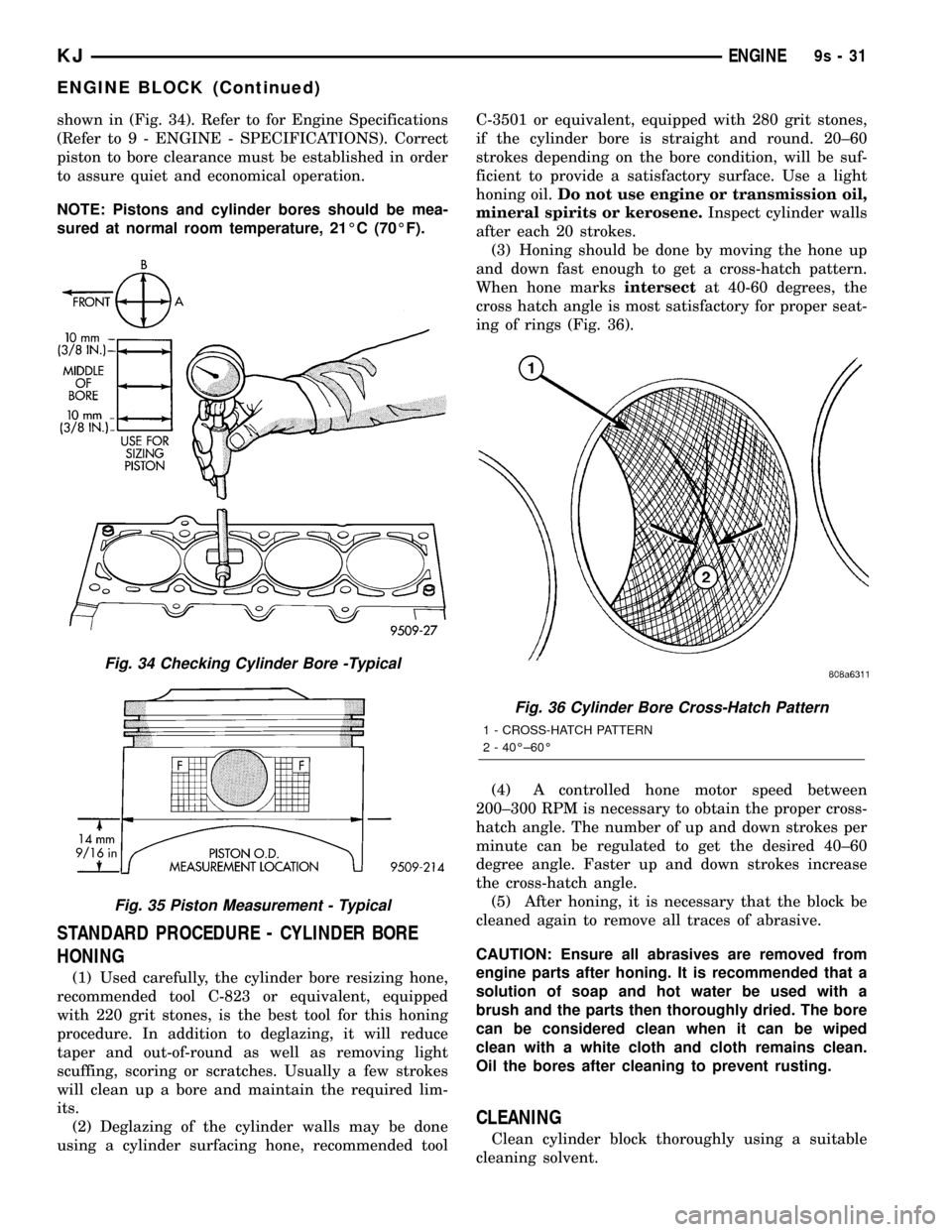
shown in (Fig. 34). Refer to for Engine Specifications
(Refer to 9 - ENGINE - SPECIFICATIONS). Correct
piston to bore clearance must be established in order
to assure quiet and economical operation.
NOTE: Pistons and cylinder bores should be mea-
sured at normal room temperature, 21ÉC (70ÉF).
STANDARD PROCEDURE - CYLINDER BORE
HONING
(1) Used carefully, the cylinder bore resizing hone,
recommended tool C-823 or equivalent, equipped
with 220 grit stones, is the best tool for this honing
procedure. In addition to deglazing, it will reduce
taper and out-of-round as well as removing light
scuffing, scoring or scratches. Usually a few strokes
will clean up a bore and maintain the required lim-
its.
(2) Deglazing of the cylinder walls may be done
using a cylinder surfacing hone, recommended toolC-3501 or equivalent, equipped with 280 grit stones,
if the cylinder bore is straight and round. 20±60
strokes depending on the bore condition, will be suf-
ficient to provide a satisfactory surface. Use a light
honing oil.Do not use engine or transmission oil,
mineral spirits or kerosene.Inspect cylinder walls
after each 20 strokes.
(3) Honing should be done by moving the hone up
and down fast enough to get a cross-hatch pattern.
When hone marksintersectat 40-60 degrees, the
cross hatch angle is most satisfactory for proper seat-
ing of rings (Fig. 36).
(4) A controlled hone motor speed between
200±300 RPM is necessary to obtain the proper cross-
hatch angle. The number of up and down strokes per
minute can be regulated to get the desired 40±60
degree angle. Faster up and down strokes increase
the cross-hatch angle.
(5) After honing, it is necessary that the block be
cleaned again to remove all traces of abrasive.
CAUTION: Ensure all abrasives are removed from
engine parts after honing. It is recommended that a
solution of soap and hot water be used with a
brush and the parts then thoroughly dried. The bore
can be considered clean when it can be wiped
clean with a white cloth and cloth remains clean.
Oil the bores after cleaning to prevent rusting.
CLEANING
Clean cylinder block thoroughly using a suitable
cleaning solvent.
Fig. 34 Checking Cylinder Bore -Typical
Fig. 35 Piston Measurement - Typical
Fig. 36 Cylinder Bore Cross-Hatch Pattern
1 - CROSS-HATCH PATTERN
2 - 40ɱ60É
KJENGINE9s-31
ENGINE BLOCK (Continued)
Page 1329 of 1803
INSPECTION
ENGINE BLOCK
(1) Clean cylinder block thoroughly and check all
core hole plugs for evidence of leaking.
(2) If new core plugs are to be installed, (Refer to 9
- ENGINE - STANDARD PROCEDURE - ENGINE
CORE AND OIL GALLERY PLUGS).
(3) Examine block and cylinder bores for cracks or
fractures.
(4) Check block deck surfaces for flatness. Deck
surface must be within service limit of 0.1 mm (0.004
in.).
CYLINDER BORE
NOTE: The cylinder bores should be measured at
normal room temperature, 21ÉC (70ÉF).
The cylinder walls should be checked for out-of-
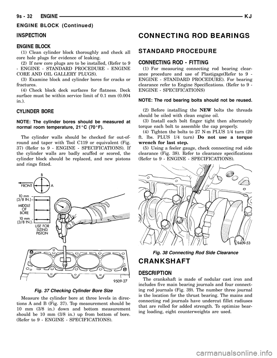
round and taper with Tool C119 or equivalent (Fig.
37) (Refer to 9 - ENGINE - SPECIFICATIONS). If
the cylinder walls are badly scuffed or scored, the
cylinder block should be replaced, and new pistons
and rings fitted.
Measure the cylinder bore at three levels in direc-
tions A and B (Fig. 37). Top measurement should be
10 mm (3/8 in.) down and bottom measurement
should be 10 mm (3/8 in.) up from bottom of bore.
(Refer to 9 - ENGINE - SPECIFICATIONS).
CONNECTING ROD BEARINGS
STANDARD PROCEDURE
CONNECTING ROD - FITTING
(1) For measuring connecting rod bearing clear-
ance procedure and use of Plastigage(Refer to 9 -
ENGINE - STANDARD PROCEDURE). For bearing
clearance refer to Engine Specifications. (Refer to 9 -
ENGINE - SPECIFICATIONS)
NOTE: The rod bearing bolts should not be reused.
(2) Before installing theNEWbolts the threads
should be oiled with clean engine oil.
(3) Install each bolt finger tight then alternately
torque each bolt to assemble the cap properly.
(4) Tighten the bolts to 27 N´m PLUS 1/4 turn (20
ft. lbs. PLUS 1/4 turn)Do not use a torque
wrench for last step.
(5) Using a feeler gauge, check connecting rod side
clearance (Fig. 38). Refer to clearance specifications
(Refer to 9 - ENGINE - SPECIFICATIONS).
CRANKSHAFT
DESCRIPTION
The crankshaft is made of nodular cast iron and
includes five main bearing journals and four connect-
ing rod journals (Fig. 39). The number three journal
is the location for the thrust bearing. The mains and
connecting rod journals have undercut fillet radiuses
that are rolled for added strength. To optimize bear-
ing loading, eight counterweights are used.
Fig. 37 Checking Cylinder Bore Size
Fig. 38 Connecting Rod Side Clearance
9s - 32 ENGINEKJ
ENGINE BLOCK (Continued)