2002 JEEP LIBERTY clock
[x] Cancel search: clockPage 1344 of 1803
(6) Install oil pressure switch and connector. (Refer
to 9 - ENGINE/LUBRICATION/OIL PRESSURE
SENSOR/SWITCH - INSTALLATION)
OIL
STANDARD PROCEDURE
ENGINE OIL LEVEL CHECK
The best time to check engine oil level is after it
has sat overnight, or if the engine has been running,
allow the engine to be shut off for at least 5 minutes
before checking oil level.
Checking the oil while the vehicle is on level
ground will improve the accuracy of the oil level
reading. Remove dipstick and observe oil level. Add
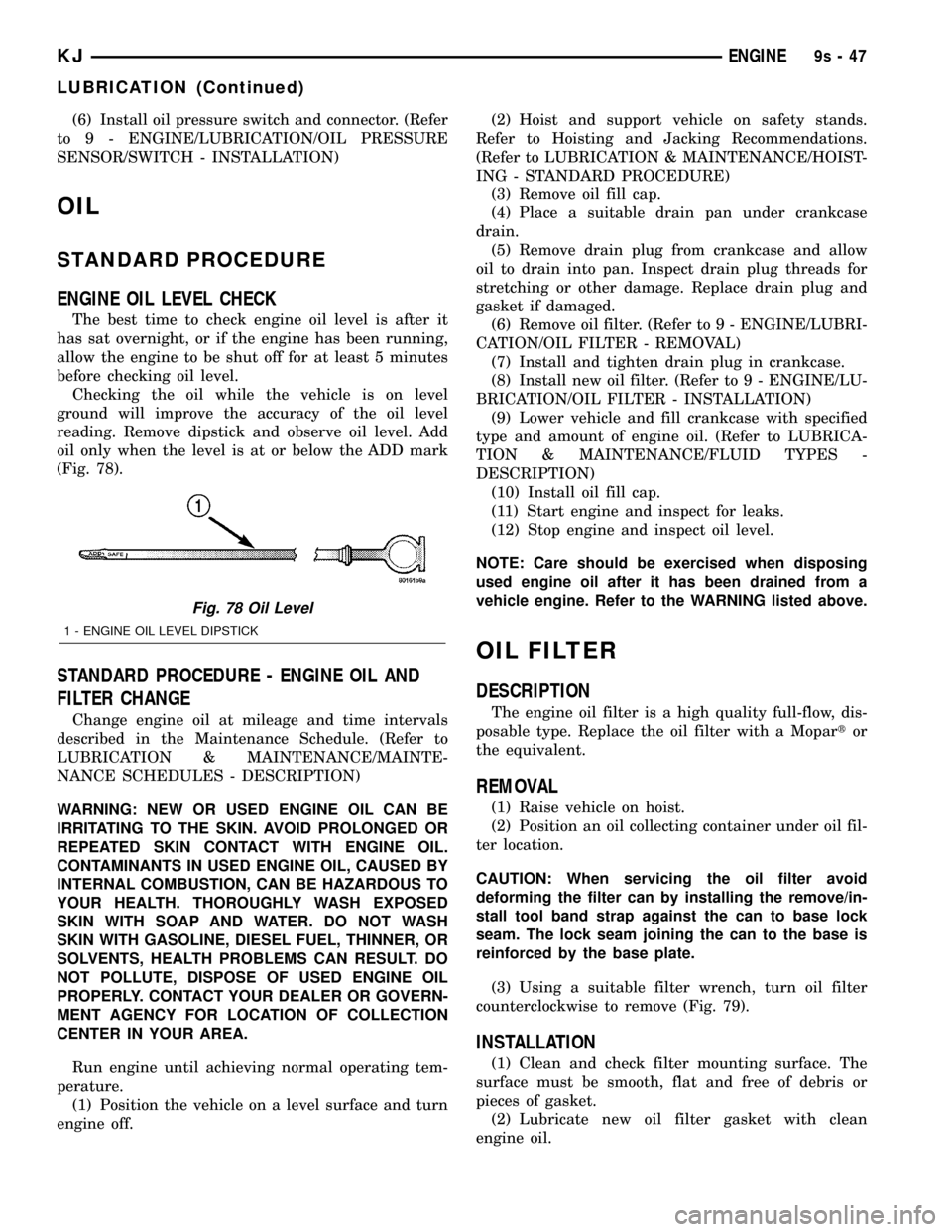
oil only when the level is at or below the ADD mark
(Fig. 78).
STANDARD PROCEDURE - ENGINE OIL AND
FILTER CHANGE
Change engine oil at mileage and time intervals
described in the Maintenance Schedule. (Refer to
LUBRICATION & MAINTENANCE/MAINTE-
NANCE SCHEDULES - DESCRIPTION)
WARNING: NEW OR USED ENGINE OIL CAN BE
IRRITATING TO THE SKIN. AVOID PROLONGED OR
REPEATED SKIN CONTACT WITH ENGINE OIL.
CONTAMINANTS IN USED ENGINE OIL, CAUSED BY
INTERNAL COMBUSTION, CAN BE HAZARDOUS TO
YOUR HEALTH. THOROUGHLY WASH EXPOSED
SKIN WITH SOAP AND WATER. DO NOT WASH
SKIN WITH GASOLINE, DIESEL FUEL, THINNER, OR
SOLVENTS, HEALTH PROBLEMS CAN RESULT. DO
NOT POLLUTE, DISPOSE OF USED ENGINE OIL
PROPERLY. CONTACT YOUR DEALER OR GOVERN-
MENT AGENCY FOR LOCATION OF COLLECTION
CENTER IN YOUR AREA.
Run engine until achieving normal operating tem-
perature.
(1) Position the vehicle on a level surface and turn
engine off.(2) Hoist and support vehicle on safety stands.
Refer to Hoisting and Jacking Recommendations.
(Refer to LUBRICATION & MAINTENANCE/HOIST-
ING - STANDARD PROCEDURE)
(3) Remove oil fill cap.
(4) Place a suitable drain pan under crankcase
drain.
(5) Remove drain plug from crankcase and allow
oil to drain into pan. Inspect drain plug threads for
stretching or other damage. Replace drain plug and
gasket if damaged.
(6) Remove oil filter. (Refer to 9 - ENGINE/LUBRI-
CATION/OIL FILTER - REMOVAL)
(7) Install and tighten drain plug in crankcase.
(8) Install new oil filter. (Refer to 9 - ENGINE/LU-
BRICATION/OIL FILTER - INSTALLATION)
(9) Lower vehicle and fill crankcase with specified
type and amount of engine oil. (Refer to LUBRICA-
TION & MAINTENANCE/FLUID TYPES -
DESCRIPTION)
(10) Install oil fill cap.
(11) Start engine and inspect for leaks.
(12) Stop engine and inspect oil level.
NOTE: Care should be exercised when disposing
used engine oil after it has been drained from a
vehicle engine. Refer to the WARNING listed above.
OIL FILTER
DESCRIPTION
The engine oil filter is a high quality full-flow, dis-
posable type. Replace the oil filter with a Mopartor
the equivalent.
REMOVAL
(1) Raise vehicle on hoist.
(2) Position an oil collecting container under oil fil-
ter location.
CAUTION: When servicing the oil filter avoid
deforming the filter can by installing the remove/in-
stall tool band strap against the can to base lock
seam. The lock seam joining the can to the base is
reinforced by the base plate.
(3) Using a suitable filter wrench, turn oil filter
counterclockwise to remove (Fig. 79).
INSTALLATION
(1) Clean and check filter mounting surface. The
surface must be smooth, flat and free of debris or
pieces of gasket.
(2) Lubricate new oil filter gasket with clean
engine oil.
Fig. 78 Oil Level
1 - ENGINE OIL LEVEL DIPSTICK
KJENGINE9s-47
LUBRICATION (Continued)
Page 1352 of 1803
TIMING BELT AND
SPROCKET(S)
REMOVAL
REMOVAL - TIMING BELT
(1) Remove air cleaner upper cover, housing, and
clean air tube.
(2) Raise vehicle on hoist.
(3) Remove accessory drive belts. (Refer to 7 -
COOLING/ACCESSORY DRIVE/BELT TENSION-
ERS - REMOVAL)
(4) Remove crankshaft vibration damper. (Refer to
9 - ENGINE/ENGINE BLOCK/VIBRATION
DAMPER - REMOVAL)
(5) Remove air conditioner/generator belt tensioner
and pulley assembly. (Refer to 7 - COOLING/ACCES-
SORY DRIVE/BELT TENSIONERS - REMOVAL)
(6) Remove timing belt lower front cover bolts and
remove cover. (Refer to 9 - ENGINE/VALVE TIMING/
TIMING BELT / CHAIN COVER(S) - REMOVAL)
(7) Lower vehicle.
(8) Remove bolts attaching timing belt upper front
cover and remove cover. (Refer to 9 - ENGINE/
VALVE TIMING/TIMING BELT / CHAIN COVER(S)
- REMOVAL)
CAUTION: When aligning crankshaft and camshaft
timing marks always rotate engine from crankshaft.
Camshaft should not be rotated after timing belt is
removed. Damage to valve components may occur.
Always align timing marks before removing timing
belt.
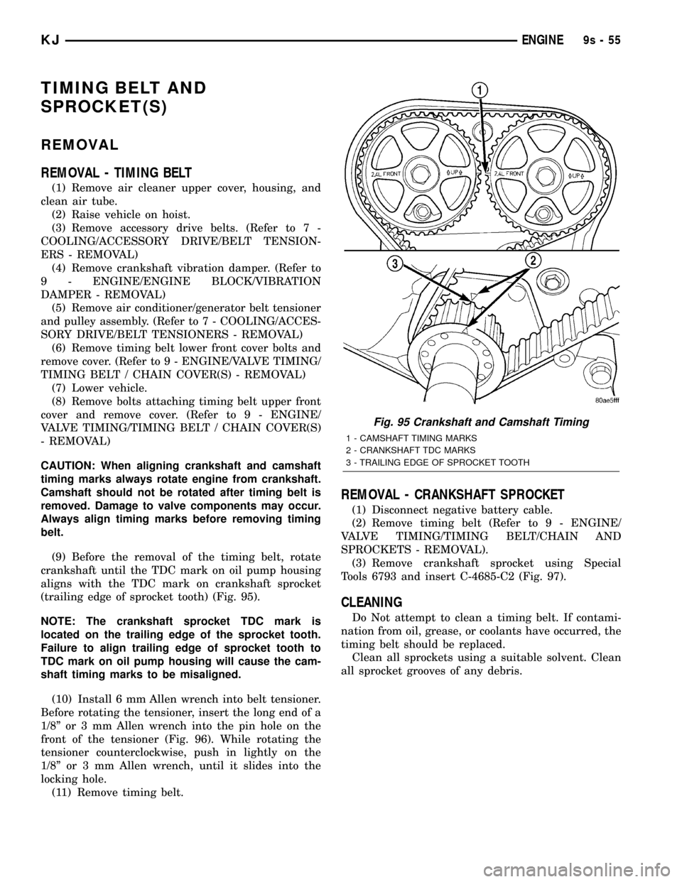
(9) Before the removal of the timing belt, rotate
crankshaft until the TDC mark on oil pump housing
aligns with the TDC mark on crankshaft sprocket
(trailing edge of sprocket tooth) (Fig. 95).
NOTE: The crankshaft sprocket TDC mark is
located on the trailing edge of the sprocket tooth.
Failure to align trailing edge of sprocket tooth to
TDC mark on oil pump housing will cause the cam-
shaft timing marks to be misaligned.
(10) Install 6 mm Allen wrench into belt tensioner.
Before rotating the tensioner, insert the long end of a
1/8º or 3 mm Allen wrench into the pin hole on the
front of the tensioner (Fig. 96). While rotating the
tensioner counterclockwise, push in lightly on the
1/8º or 3 mm Allen wrench, until it slides into the
locking hole.
(11) Remove timing belt.
REMOVAL - CRANKSHAFT SPROCKET
(1) Disconnect negative battery cable.
(2) Remove timing belt (Refer to 9 - ENGINE/
VALVE TIMING/TIMING BELT/CHAIN AND
SPROCKETS - REMOVAL).
(3) Remove crankshaft sprocket using Special
Tools 6793 and insert C-4685-C2 (Fig. 97).
CLEANING
Do Not attempt to clean a timing belt. If contami-
nation from oil, grease, or coolants have occurred, the
timing belt should be replaced.
Clean all sprockets using a suitable solvent. Clean
all sprocket grooves of any debris.
Fig. 95 Crankshaft and Camshaft Timing
1 - CAMSHAFT TIMING MARKS
2 - CRANKSHAFT TDC MARKS
3 - TRAILING EDGE OF SPROCKET TOOTH
KJENGINE9s-55
Page 1354 of 1803
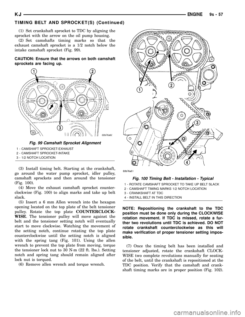
(1) Set crankshaft sprocket to TDC by aligning the
sprocket with the arrow on the oil pump housing.
(2) Set camshafts timing marks so that the
exhaust camshaft sprocket is a 1/2 notch below the
intake camshaft sprocket (Fig. 99).
CAUTION: Ensure that the arrows on both camshaft
sprockets are facing up.
(3) Install timing belt. Starting at the crankshaft,
go around the water pump sprocket, idler pulley,
camshaft sprockets and then around the tensioner
(Fig. 100).
(4) Move the exhaust camshaft sprocket counter-
clockwise (Fig. 100) to align marks and take up belt
slack.
(5) Inserta6mmAllen wrench into the hexagon
opening located on the top plate of the belt tensioner
pulley. Rotate the top plateCOUNTERCLOCK-
WISE. The tensioner pulley will move against the
belt and the tensioner setting notch will eventually
start to move clockwise. Watching the movement of
the setting notch, continue rotating the top plate
counterclockwise until the setting notch is aligned
with the spring tang (Fig. 101). Using the allen
wrench to prevent the top plate from moving, torque
the tensioner lock nut to 30 N´m (22 ft. lbs.). Setting
notch and spring tang should remain aligned after
lock nut is torqued.
(6) Remove allen wrench and torque wrench.NOTE: Repositioning the crankshaft to the TDC
position must be done only during the CLOCKWISE
rotation movement. If TDC is missed, rotate a fur-
ther two revolutions until TDC is achieved. DO NOT
rotate crankshaft counterclockwise as this will
make verification of proper tensioner setting impos-
sible.
(7) Once the timing belt has been installed and
tensioner adjusted, rotate the crankshaft CLOCK-
WISE two complete revolutions manually for seating
of the belt, until the crankshaft is repositioned at the
TDC position. Verify that the camshaft and crank-
shaft timing marks are in proper position (Fig. 102).
Fig. 99 Camshaft Sprocket Alignment
1 - CAMSHAFT SPROCKET-EXHAUST
2 - CAMSHAFT SPROCKET-INTAKE
3 - 1/2 NOTCH LOCATION
Fig. 100 Timing Belt - Installation - Typical
1 - ROTATE CAMSHAFT SPROCKET TO TAKE UP BELT SLACK
2 - CAMSHAFT TIMING MARKS 1/2 NOTCH LOCATION
3 - CRANKSHAFT AT TDC
4 - INSTALL BELT IN THIS DIRECTION
KJENGINE9s-57
TIMING BELT AND SPROCKET(S) (Continued)
Page 1360 of 1803
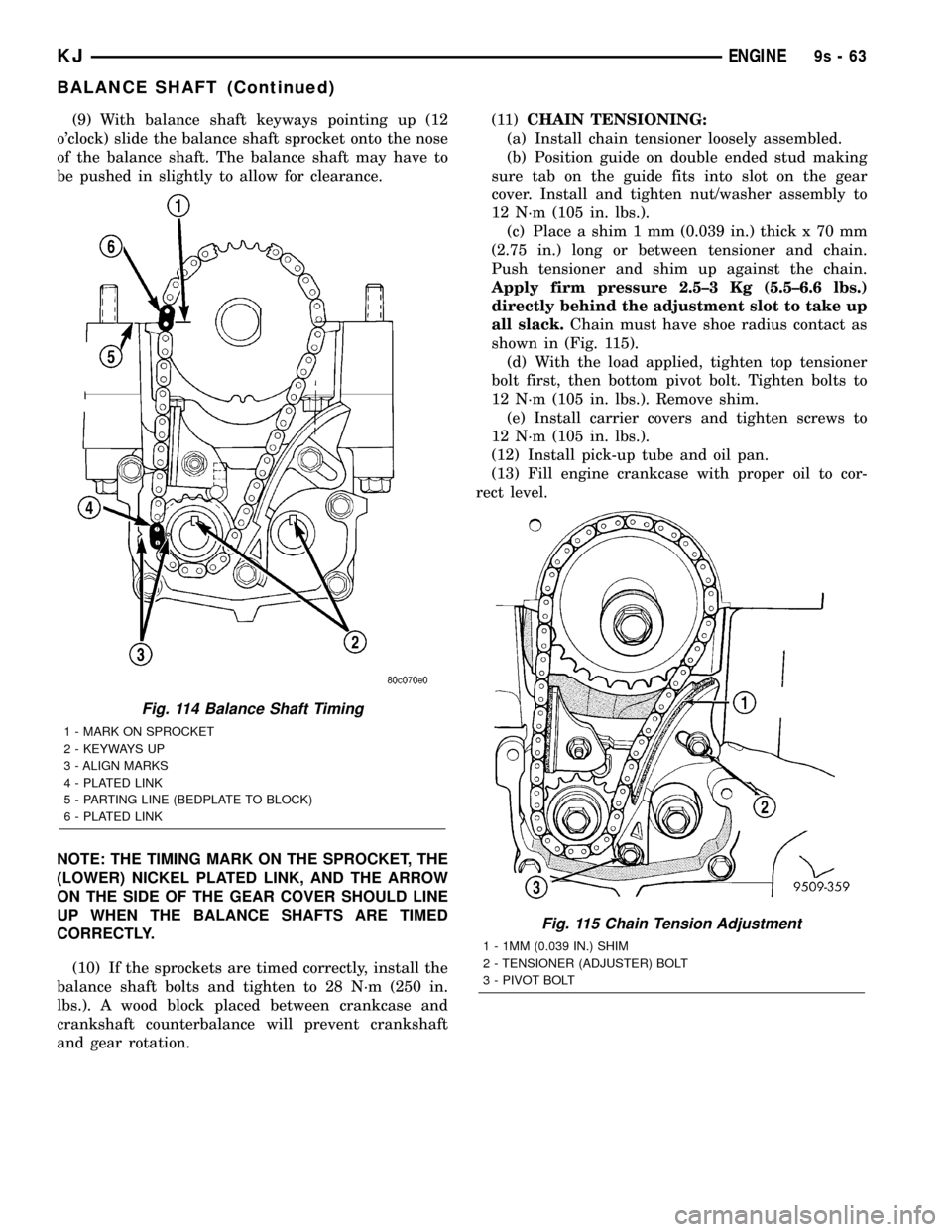
(9) With balance shaft keyways pointing up (12
o'clock) slide the balance shaft sprocket onto the nose
of the balance shaft. The balance shaft may have to
be pushed in slightly to allow for clearance.
NOTE: THE TIMING MARK ON THE SPROCKET, THE
(LOWER) NICKEL PLATED LINK, AND THE ARROW
ON THE SIDE OF THE GEAR COVER SHOULD LINE
UP WHEN THE BALANCE SHAFTS ARE TIMED
CORRECTLY.
(10) If the sprockets are timed correctly, install the
balance shaft bolts and tighten to 28 N´m (250 in.
lbs.). A wood block placed between crankcase and
crankshaft counterbalance will prevent crankshaft
and gear rotation.(11)CHAIN TENSIONING:
(a) Install chain tensioner loosely assembled.
(b) Position guide on double ended stud making
sure tab on the guide fits into slot on the gear
cover. Install and tighten nut/washer assembly to
12 N´m (105 in. lbs.).
(c) Place a shim 1 mm (0.039 in.) thick x 70 mm
(2.75 in.) long or between tensioner and chain.
Push tensioner and shim up against the chain.
Apply firm pressure 2.5±3 Kg (5.5±6.6 lbs.)
directly behind the adjustment slot to take up
all slack.Chain must have shoe radius contact as
shown in (Fig. 115).
(d) With the load applied, tighten top tensioner
bolt first, then bottom pivot bolt. Tighten bolts to
12 N´m (105 in. lbs.). Remove shim.
(e) Install carrier covers and tighten screws to
12 N´m (105 in. lbs.).
(12) Install pick-up tube and oil pan.
(13) Fill engine crankcase with proper oil to cor-
rect level.
Fig. 114 Balance Shaft Timing
1 - MARK ON SPROCKET
2 - KEYWAYS UP
3 - ALIGN MARKS
4 - PLATED LINK
5 - PARTING LINE (BEDPLATE TO BLOCK)
6 - PLATED LINK
Fig. 115 Chain Tension Adjustment
1 - 1MM (0.039 IN.) SHIM
2 - TENSIONER (ADJUSTER) BOLT
3 - PIVOT BOLT
KJENGINE9s-63
BALANCE SHAFT (Continued)
Page 1400 of 1803
(17) When LCS adapter test leads are attached
into relay cavities, fuel pumpwill be activated.
Determine fuel pump amperage on DRB screen.
Amperage should be below 10.0 amps. If amperage is
below 10.0 amps, and specifications for the Fuel
Pump Pressure, Fuel Pump Capacity and Fuel Pres-
sure Leak Down tests were met, the fuel pump mod-
ule is OK.
(18) If amperage is more than 10.0 amps, replace
fuel pump module assembly. The electric fuel pump
is not serviced separately.
(19) Disconnect test leads from relay cavities
immediately after testing.
FUEL PUMP MODULE
DESCRIPTION
The fuel pump module assembly is located in the
fuel tank (Fig. 1). The assembly is divided into 2±sec-
tions, upper and lower. The lower section is locked to
the bottom of the fuel tank. The complete assembly
contains the following components:
²A fuel pressure regulator
²A separate fuel pick-up, or inlet filter
²An electric fuel pump
²A lockring to retain upper section of pump mod-
ule to tank
²A rollover valve
²A vent fitting for ORVR system
²A soft gasket between tank flange and module
²A fuel gauge sending unit (fuel level sensor)
²Two fuel line connections (supply and return)
The fuel gauge sending unit may be serviced sepa-
rately. If the electrical fuel pump, primary inlet filter
or fuel pressure regulator require service, the lower
section of the fuel pump module must be replaced.
OPERATION
Refer to Fuel Pump, Inlet Filter, Fuel Pressure
Regulator and Fuel Gauge Sending Unit.
REMOVAL
The fuel pump module is divided into 2 sections,
upper and lower. To service the check (control) valve,
replace only the upper section. To service the fuel
gauge sending unit, remove the upper section. To ser-
vice the electric fuel pump, fuel pressure regulator or
primary inlet filter, remove both sections and replace
lower section.
Fuel tank removal will not be necessary for
fuel pump module removal. Access is from rear
cargo area.
(1) Four cargo holdown clamps are located inside
the vehicle on the floor of the rear cargo area.Remove the 2 rearward mounted clamps by drilling
out the clamp rivets.
(2) Fold carpeting forward to gain access to fuel
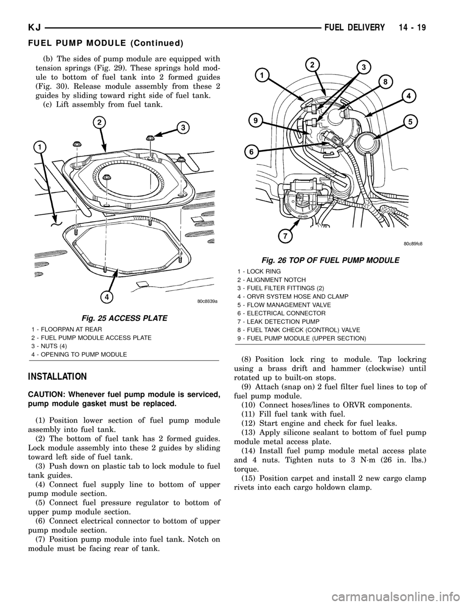
pump module access plate (Fig. 25).
(3) Remove 4 fuel pump module access plate nuts
(Fig. 25).
(4) While applying heat from a heat gun, carefully
pry up fuel pump module access plate. Take care not
to bend plate.
(5) Thoroughly clean area around top of pump
module to prevent contaminants from entering fuel
tank or fuel lines.
WARNING: THE FUEL SYSTEM IS UNDER A CON-
STANT PRESSURE EVEN WITH ENGINE OFF.
BEFORE SERVICING THE FUEL PUMP MODULE,
FUEL SYSTEM PRESSURE MUST BE RELEASED.
(6) Release fuel system pressure. Refer to Fuel
System Pressure Release procedure.
(7) Disconnect 2 fuel lines at fuel pump module
(Fig. 26) by pressing on 2 buttons at sides of fitting.
(8) Disconnect electrical connector (Fig. 26) at top
of fuel pump module by sliding red colored tab first
to unlock, and push grey colored tab down for
removal.
(9) Disconnect ORVR hose clamp and hose (Fig.
26) at pump module fitting.
(10) Remove module lockring (Fig. 26) using a
brass drift and hammer (counter-clockwise).
(11) Carefully lift upper section of pump module
(Fig. 26) from fuel tank exposing connections(lift
upper section from tank very slowly until rub-
ber gasket can be retained. If not, gasket will
fall into fuel tank.)
(a) Disconnect electrical connector (Fig. 27) at
bottom of upper pump module section.
(b) Disconnect fuel pressure regulator (Fig. 27)
at bottom of upper pump module section. Press on
2 locking tabs.
(c) Disconnect fuel return line (Fig. 27) at bot-
tom of upper pump module section. Press on 2
locking tabs.
(d) Remove upper section of pump module (Fig.
28) from fuel tank.
(12) Using an approved gas holding tank, drain
fuel tank through pump module opening.If check
(control) valve, or, only upper section of pump
module is being serviced, tank draining is not
necessary. If any other fuel pump module com-
ponent is being serviced, the tank must be com-
pletely drained to the bottom.
(13) To remove lower section of pump module from
fuel tank:
(a) Using finger pressure, push on plastic
release tab (Fig. 29) while sliding lock tab upward.
14 - 18 FUEL DELIVERYKJ
FUEL PUMP (Continued)
Page 1401 of 1803
(b) The sides of pump module are equipped with
tension springs (Fig. 29). These springs hold mod-
ule to bottom of fuel tank into 2 formed guides
(Fig. 30). Release module assembly from these 2
guides by sliding toward right side of fuel tank.
(c) Lift assembly from fuel tank.
INSTALLATION
CAUTION: Whenever fuel pump module is serviced,
pump module gasket must be replaced.
(1) Position lower section of fuel pump module
assembly into fuel tank.
(2) The bottom of fuel tank has 2 formed guides.
Lock module assembly into these 2 guides by sliding
toward left side of fuel tank.
(3) Push down on plastic tab to lock module to fuel
tank guides.
(4) Connect fuel supply line to bottom of upper
pump module section.
(5) Connect fuel pressure regulator to bottom of
upper pump module section.
(6) Connect electrical connector to bottom of upper
pump module section.
(7) Position pump module into fuel tank. Notch on
module must be facing rear of tank.(8) Position lock ring to module. Tap lockring
using a brass drift and hammer (clockwise) until
rotated up to built-on stops.
(9) Attach (snap on) 2 fuel filter fuel lines to top of
fuel pump module.
(10) Connect hoses/lines to ORVR components.
(11) Fill fuel tank with fuel.
(12) Start engine and check for fuel leaks.
(13) Apply silicone sealant to bottom of fuel pump
module metal access plate.
(14) Install fuel pump module metal access plate
and 4 nuts. Tighten nuts to 3 N´m (26 in. lbs.)
torque.
(15) Position carpet and install 2 new cargo clamp
rivets into each cargo holdown clamp.
Fig. 25 ACCESS PLATE
1 - FLOORPAN AT REAR
2 - FUEL PUMP MODULE ACCESS PLATE
3 - NUTS (4)
4 - OPENING TO PUMP MODULE
Fig. 26 TOP OF FUEL PUMP MODULE
1 - LOCK RING
2 - ALIGNMENT NOTCH
3 - FUEL FILTER FITTINGS (2)
4 - ORVR SYSTEM HOSE AND CLAMP
5 - FLOW MANAGEMENT VALVE
6 - ELECTRICAL CONNECTOR
7 - LEAK DETECTION PUMP
8 - FUEL TANK CHECK (CONTROL) VALVE
9 - FUEL PUMP MODULE (UPPER SECTION)
KJFUEL DELIVERY 14 - 19
FUEL PUMP MODULE (Continued)
Page 1408 of 1803
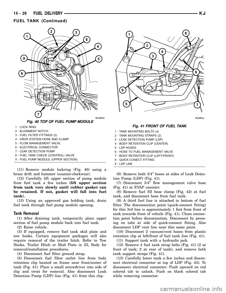
(11) Remove module lockring (Fig. 40) using a
brass drift and hammer (counter-clockwise).
(12) Carefully lift upper section of pump module
from fuel tank a few inches(lift upper section
from tank very slowly until rubber gasket can
be retained. If not, gasket will fall into fuel
tank).
(13) Using an approved gas holding tank, drain
fuel tank through fuel pump module opening.
Tank Removal
(1) After draining tank, temporarily place upper
section of fuel pump module back into fuel tank.
(2) Raise vehicle.
(3) If equipped, remove fuel tank skid plate and
tow hooks. Certain equipment packages will also
require removal of the trailer hitch. Refer to Tow
Hooks, Trailer Hitch or Skid Plate in 23, Body for
removal/installation procedures.
(4) Disconnect fuel filter ground strap.
(5) Disconnect fuel filter outlet line from body
retention clip located on frame near front/center of
tank (Fig. 41). Place a small screwdriver into side of
clip and twist for removal. Also disconnect Leak
Detection Pump (LDP) line (Fig. 41) from this clip.(6) Remove both 3/4º hoses at sides of Leak Detec-
tion Pump (LDP) (Fig. 41).
(7) Disconnect 3/4º flow management valve hose
(Fig. 41) at EVAP canister.
(8) Remove fuel fill hose clamp (Fig. 42) at fuel
tank, and disconnect hose from fuel tank.
(9) A third fuel line is attached to bottom of fuel
filter. The disconnection point (quick-connect fitting)
for this 3rd line is approximately 1 foot from front of
tank towards front of vehicle (Fig. 41). Clean connec-
tion point before disconnection. Disconnect by press-
ing on tabs at side of quick-connect fitting. Also
disconnect LDP vent line near this same point.
(10) Disconnect 2 vacuum/vent hoses from plastic
retention clip at left/front of fuel tank line (Fig. 41).
(11) Support tank with a hydraulic jack.
(12) Remove 4 fuel tank strap bolts (Fig. 41) (2 at
front of tank; 2 at rear of tank), and remove both
tank support straps (Fig. 41).
(13) Carefully lower tank a few inches and discon-
nect electrical connector at top of LDP (Fig. 43). To
disconnect electrical connector: Push upward on red
colored tab to unlock. Push on black colored tab
while removing connector.
Fig. 40 TOP OF FUEL PUMP MODULE
1 - LOCK RING
2 - ALIGNMENT NOTCH
3 - FUEL FILTER FITTINGS (2)
4 - ORVR SYSTEM HOSE AND CLAMP
5 - FLOW MANAGEMENT VALVE
6 - ELECTRICAL CONNECTOR
7 - LEAK DETECTION PUMP
8 - FUEL TANK CHECK (CONTROL) VALVE
9 - FUEL PUMP MODULE (UPPER SECTION)Fig. 41 FRONT OF FUEL TANK
1 - TANK MOUNTING BOLTS (4)
2 - TANK MOUNTING STRAPS (2)
3 - LEAK DETECTION PUMP (LDP)
4 - BODY RETENTION CLIP (CENTER)
5 - LDP HOSES
6 - HOSE TO FUEL MANAGEMENT VALVE
7 - BODY RETENTION CLIP (LEFT/FRONT)
8 - QUICK-CONECT FITTING
9 - LDP LINE
14 - 26 FUEL DELIVERYKJ
FUEL TANK (Continued)
Page 1419 of 1803
The resistance values of the IAT sensor is the same
as for the Engine Coolant Temperature (ECT) sensor.
REMOVAL
2.4L
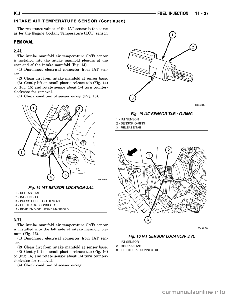
The intake manifold air temperature (IAT) sensor
is installed into the intake manifold plenum at the
rear end of the intake manifold (Fig. 14).
(1) Disconnect electrical connector from IAT sen-
sor.
(2) Clean dirt from intake manifold at sensor base.
(3) Gently lift on small plastic release tab (Fig. 14)
or (Fig. 15) and rotate sensor about 1/4 turn counter-
clockwise for removal.
(4) Check condition of sensor o-ring (Fig. 15).
3.7L
The intake manifold air temperature (IAT) sensor
is installed into the left side of intake manifold ple-
num (Fig. 16).
(1) Disconnect electrical connector from IAT sen-
sor.
(2) Clean dirt from intake manifold at sensor base.
(3) Gently lift on small plastic release tab (Fig. 16)
or (Fig. 15) and rotate sensor about 1/4 turn counter-
clockwise for removal.
(4) Check condition of sensor o-ring.
Fig. 14 IAT SENSOR LOCATION-2.4L
1 - RELEASE TAB
2 - IAT SENSOR
3 - PRESS HERE FOR REMOVAL
4 - ELECTRICAL CONNECTOR
5 - REAR END OF INTAKE MANIFOLD
Fig. 15 IAT SENSOR TAB / O-RING
1 - IAT SENSOR
2 - SENSOR O-RING
3 - RELEASE TAB
Fig. 16 IAT SENSOR LOCATION- 3.7L
1 - IAT SENSOR
2 - RELEASE TAB
3 - ELECTRICAL CONNECTOR
KJFUEL INJECTION 14 - 37
INTAKE AIR TEMPERATURE SENSOR (Continued)